SIIG AV-GM04T3-S1 Series User manual

Enhanced HDMI Extender over Single Cat.X
with HDBaseT-Lite, Bi-directional IR & PoC
P/N: AV-GM04T3-S1

Safety and Notice
The AV-GM04T3-S1 Enhanced HDMI Extender over Single Cat.X with HDBaseT-Lite,
Bi-directional IR & PoC has been tested for conformance to safety regulations and
requirements, and has been certified for international use. However, like all electronic
equipment, the AV-GM04T3-S1 should be used with care. Please read and follow the safety
instructions to protect yourself from possible injury and to minimize the risk of damage to the
unit.
●Follow all instructions and warnings marked on this unit.
●Do not attempt to service this unit yourself, except where explained in this manual.
●Provide proper ventilation and air circulation and do not use near water.
●Keep objects that might damage the device and assure that the placement of this unit is on a
stable surface.
●Use only the power adapter and power cords and connection cables designed for this unit.
●Do not use liquid or aerosol cleaners to clean this unit. Always unplug the power to the
device before cleaning.
TABLE OF CONTENTS
INTRODUCTION.................................................................................................................1
FEATURES.........................................................................................................................1
SPECIFICATIONS..............................................................................................................2
PACKAGE CONTENTS......................................................................................................3
CONNECTION DIAGRAM ..................................................................................................3
PANEL DESCRIPTIONS.....................................................................................................4
Transmitting unit......................................................................................................4
Receiving unit..........................................................................................................5
IR PASS-THROUGH...........................................................................................................6
HDMI PIN DEFINITION.......................................................................................................7
HARDWARE INSTALLATION.............................................................................................7
NOTICE..............................................................................................................................9
WARRANTY .....................................................................................................................10

1
INTRODUCTION
The AV-GM04T3-S1 Enhanced HDMI Extender over Single Cat.X with HDBaseT-Lite,
Bi-directional IR & PoC boosts up your video/audio transmission distance to 60m (198ft) in HDTV
1080p with 48-bit color depth. The new generation enhanced technology is to make sure the
HDBaseT extender can work properly even though source and display are both compliant with
HDMI2.0a and HDCP2.2. AV-GM04T3-S1 also supports the most advanced 3D video format
complaint with HDMI specification and therefore guarantees the highest 3D video compatibility on
the market. With only one cost- effective Cat.5/5e/6 cable, users can readily extend HDTV sources
from DVD players, Blu-ray Disc player, PS3, PC, and any other kinds of sources compliant with TMDS
to distant display monitors including HDMI or DVI enabled TV sets or LCD PC monitors. With the
advanced design for the latest HDMI technology, deep color video, DTS-HD or Dolby TrueHD audio,
and HDCP supports and compatibility are all further insured. AV-GM04T3-S1 is also equipped with
bi-directional IR pass-through path. These bonus features allow users to boost IR control distance
up to 60m (198ft) through only single Cat.5/5e/6 cable with HDMI signals. In addition,
AV-GM04T3-S1 also supports PoC (Power over Cable) which can power both units from either TX or
RX with power supply.
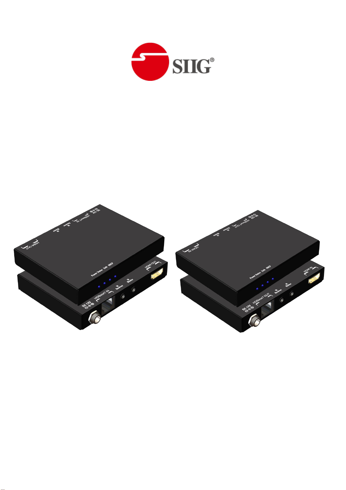
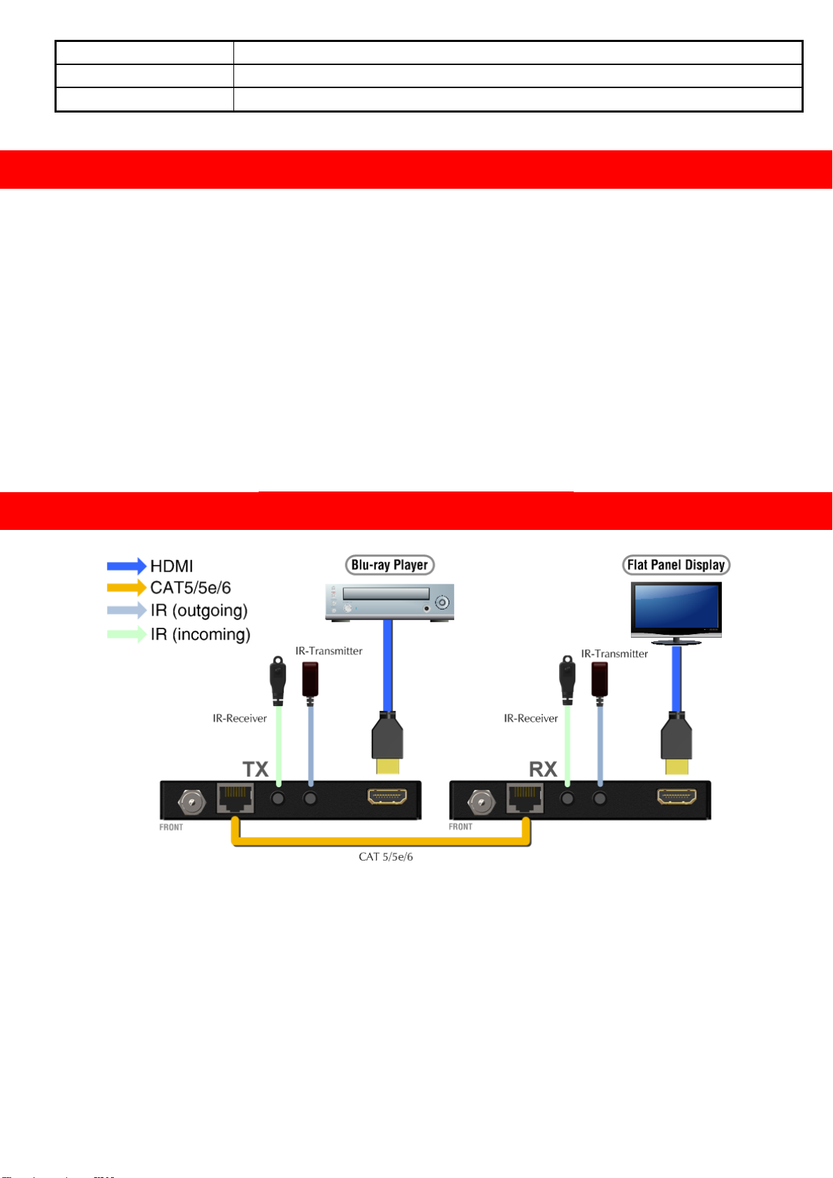
The AV-GM04T3-S1 includes two units: transmitting unit AV-GM04T3-S1-TX and receiving unit
AV-GM04T3-S1-RX. The transmitting unit is used to capture the input HDMI / DVI signals with IR
control packets and carry the signals via one cost effective Cat.5/5e/6 cable. The receiving unit is
responsible for equalizing the transmitted HDMI signal and reconstructing IR and serial control
signals. AV-GM04T3-S1 offers the most convenient solution for digital signage with long distance
A/V transmission path. With 10G transmission width, AV-GM04T3-S1 is ready for your next HDMI
generation and applications!
FEATURES
●Supports HDMI Deep Color & full 3D & 4K2K@30 (HDBaseT technology)
●Extend the transmission up to 60m (198ft) from the HDMI source at Full HD 1080p 48-bit and
35m (114ft) at 4K2K@30
●Supports PoC(Power over Cable) which can power both units from TX or RX side with power
supply
●Supports EDID adjustment mechanism for HDMI2.0 at pixel clock higher than 340 MHz
●HDCP & EDID Bypass
●CEC support
●Auto equalization
●Pure unaltered uncompressed 7.1ch digital HDMI over Cat.5/5e/6 cable transmission
●DTS-HD Master Audio and Dolby TrueHD high bit rate audio support
●Supports full frequency IR signal from 20KHz to 60KHz
●Bi-directional IR path-through
●Wall mounting housing design for easy and robust installation

2
SPECIFICATIONS
Model Name
AV-GM04T3-S1
Technical
AV-GM04T3-S1[Tx]
AV-GM04T3-S1[Rx]
Role of usage
Transmitter [TX]
Receiver [RX]
HDMI compliance
HDMI Deep Color, full 3D & 4K2K@30
HDCP compliance
Yes
Video bandwidth
Single-link 340MHz [10.2Gbps]
Video support
480i / 480p / 720p / 1080i / 1080p60
HDMI over UTP
1080p@60 60m (198ft) [CAT5e]
Audio support
Surround sound [up to 7.1ch) or stereo digital audio
Equalization
Auto
Input TMDS signal
1.2 Volts [peak-to-peak]
Input DDC signal
5 Volts [peak-to-peak, TTL]
ESD protection
Human body model —±15kV [air-gap discharge] & ±8kV [contact discharge]
PCB stack-up
6-layer board [impedance control —differential 100Ω; single 50Ω]
IR pass-thru
Bi-directional
RS-232 support
Yes
PoC support
Yes
Input
1x HDMI
1x 3.5mm
1x RJ-45
1x 3.5mm
Output
1x RJ-45
1x 3.5mm
1x HDMI
1x 3.5mm
In / Out
N/A
N/A
HDMI source control
Controllable via IR pass-through from RX to TX with IR extenders
HDMI connector
Type A [19-pin female]
Min DIN connector
DIN-9
RJ-45 connector
WE/SS 8P8C(Reverse Mode)
Rotary control switch
None
3.5mm connector
IR receiver / IR blaster
Mechanical
AV-GM04T3-S1[Tx]
AV-GM04T3-S1[Rx]
Housing
Metal enclosure
Dimensions
[L x W x H]
Model
98.5 x 73.4 x 14.3mm [3.9" x 2.9" x 0.6"]
Package
128 x 175 x 134mm [5" x 6.9" x 5.3"]
Carton
647 x 366 x 290mm [1'6" x 1'3" x 11.8"]
Weight
Model
160g [5.6 oz]
160g [5.6 oz]
Package
720g [1.6 lbs]
Fixedness
Wall-mounting case with screws
Power supply
12V 1.5A DC
Power consumption
3 Watt [max]
7 Watt [max]
The length depends on the characteristics and quality of the cables. Higher resolutions and
longer transmission distances require low skew cables (<25ns/100m) for best performance.
Unshielded CAT6 with metal RJ45 connectors is recommended.

3
Operation temperature
0~40°C [32~104°F]
Storage temperature
-20~60°C [-4~140°F]
Relative humidity
20~90% RH [no condensation]
PACKAGE CONTENTS
●1x AV-GM04T3-S1 [TX & RX]
●1x IR blaster
●1x IR receiver
●1x DC 12V 1.5A in-line with C7 power cord
●1x User Manual
CONNECTION DIAGRAM

4
PANEL DESCRIPTIONS
Transmitting unit ►AV-GM04T3-S1-TX
Front Panel
1. LED: Power LED, Status LED, Link LED, HDCP LED
(1) Power LED: This LED light always shine is meant that works fine.
(2) Status LED: This LED light is blinking it means functions well.
(3) Link LED: This LED light always shine is meant that works fine.
(4) HDCP LED: HDCP ON –the LED light always shine
HDCP LED: HDCP OFF –the LED light is blinking
Rear Panel
2. Latch-locking power jack: Connect to 12V DC power supply
3. RJ45: Plug in a Cat-5/5e/6 cable that needs to be linked to the receiving unit AV-GM04T3-S1-RX
4. IR Receiver: Infrared 3.5mm socket for plugging in the extension cable of IR receiver
5. IR Blaster: Infrared 3.5mm socket for plugging in the extension cable of IR blaster
6. HDMI IN: Connects to a HDMI source with HDMI male-male cable

5
Receiving unit ►AV-GM04T3-S1-RX
Front Panel
7. LED: Power LED, Status LED, Link LED, HDCP LED
(1) Power LED: This LED light always shine is meant that works fine.
(2) Status LED: This LED light is blinking it means functions well.
(3) Link LED: This LED light always shine is meant that works fine.
(4) HDCP LED: HDCP ON –the LED light always shine
HDCP LED: HDCP OFF –the LED light is blinking
Rear Panel
8. Latch-locking power jack: Connect to 12V DC power supply

6
9. RJ45: Plug in a Cat-5/5e/6 cable that needs to be linked to the receiving unit AV-GM04T3-S1-TX
10. IR Receiver: Infrared 3.5mm socket for plugging in the extension cable of IR receiver
11. IR Blaster: Infrared 3.5mm socket for plugging in the extension cable of IR blaster
12. HDMI OUT: Connects to a HDMI display with HDMI male-male cable
IR PASS-THROUGH
IR Extenders
IR Blaster
IR Receiver
IR Sockets
IR BLASTER: plug in the IR blaster to emit all IR command signals received from the IR receiver
from the other enf to control the devices corresponding to the IR signals.
IR RECEIVER: plug in the IR receiver to receive all IR command signals from the IR remote controls of
the corresponding devices.
Definition of IR Earphone Jack
IR Blaster
IR Receiver
Incorrect placement of IR Blaster and Receiver may result in the failure of the IR
extenders. Please check carefully before plugging in the IR extender to the
respective IR sockets. Warranty will not cover the damage.
CAUTION!

7
HDMI PIN DEFINITION
Type A (Receptacle) HDMI
Pin 1
TMDS Data2+
Pin 11
TMDS Clock Shield
Pin 2
TMDS Data2 Shield
Pin 12
TMDS Clock–
Pin 3
TMDS Data2–
Pin 13
NC
Pin 4
TMDS Data1+
Pin 14
Reserved (N.C. on device)
Pin 5
TMDS Data1 Shield
Pin 15
SCL
Pin 6
TMDS Data1–
Pin 16
SDA
Pin 7
TMDS Data0+
Pin 17
DDC/CEC Ground
Pin 8
TMDS Data0 Shield
Pin 18
+5V Power
Pin 9
TMDS Data0–
Pin 19
Hot Plug Detect
Pin 10
TMDS Clock+
HARDWARE INSTALLATION
You can buy any IR extension cables in the market that are compatible to the definition of
the IR sockets for the extender if necessary for replacement use. However, IR cables longer
than 2m (6-ft) may not work.

8
1. Connect a HDMI or DVI source (such as a Blu-ray Disc player) to the transmitting unit
AV-GM04T3-S1-TX.
2. Connect a HDMI or DVI display (such as a LCD TV) to the receiving unit AV-GM04T3-S1-RX.
3. Connect IR Blaster/Receiver to both TX and RX units.
4. Connect a Cat-5/5e/6 cable between the transmitting and receiving units.
5. Make sure this Cat-5/5e/6 cable is tightly connected
6. Plug in 12V DC power supply unit to the power jack of the receiving unit AV-GM04T3-S1-RX or
the transmitting unit AV-GM04T3-S1-TX.

9
NOTICE
1. All HDMI over CAT5 transmission distances are measured using Belden 1583A CAT5e 125MHz
UTP cable and ASTRODESIGN Video Signal Generator VG-859C & VG-870B.
2. Incorrect placement of IR Blaster and Receiver may result in the failure of the IR extenders.
Please check carefully before plugging in the IR extender to the respective IR sockets. Warranty
will not cover the damage.
3. The transmission length is largely affected by the type of Cat-5/5e/6 cables, the type of HDMI
sources, and the type of HDMI display. The testing result shows solid UTP cables (usually in the
form of 300m [1,000ft] bulk cables) can transmit a lot longer signals than stranded UTP cables
(usually in the form of fixed length patch cords). Shielded STP cables are better suited than
unshielded UTP cables. A solid UTP Cat-5e cable shows longer transmission range than stranded
STP Cat-6 cable. For long extension applications, solid UTP/STP cables are the only viable choice.
4. EIA/TIA-568-B termination (T568B) for Cat-5/5e/6 cables is recommended for better
performance.
5. To reduce the interference among the unshielded twisted pairs of wires in Cat-5/5e/6 cable, one
can use shielded STP cables to improve EMI problems, which is worsen in long transmission.
6. Because the quality of the CAT5/6 cables has the major effect on how long the transmission limit
can achieve and how good is the received picture quality, the actual transmission range is
subject to one’s choice of Cat-5/5e/6 cables. For desired resolutions greater than 1080i or
1280x1024, a Cat-6 cable is recommended.
7. If your HDMI display has multiple HDMI inputs, it is found that the first HDMI input [HDMI input
#1] generally can produce better transmission performance among all HDMI inputs.

10
WARRANTY
The SELLER warrants the AV-GM04T3-S1 Enhanced HDMI Extender over Single Cat.X with
HDBaseT-Lite, Bi-directional IR & PoC free from defects in the material and workmanship for 3
years from the date of purchase from the SELLER or an authorized dealer. Should this product fail
to be in good working order within 3 years warranty period, The SELLER, at its option, repair or
replace the unit, provided that the unit has not been subjected to accident, disaster, abuse or any
unauthorized modifications including static discharge and power surge. This warranty is offered by
the SELLER for its BUYER with direct transaction only. This warranty is void if the warranty seal on
the metal housing is broken.
Unit that fails under conditions other than those covered will be repaired at the current price of
parts and labor in effect at the time of repair. Such repairs are warranted for 90 days from the day
of reshipment to the BUYER. If the unit is delivered by mail, customers agree to insure the unit or
assume the risk of loss or damage in transit. Under no circumstances will a unit be accepted
without a return authorization number.
The warranty is in lieu of all other warranties expressed or implied, including without
limitations, any other implied warranty or fitness or merchantability for any particular purpose, all
of which are expressly disclaimed.
Proof of sale may be required in order to claim warranty. Customers outside Taiwan are
responsible for shipping charges to and from the SELLER. Cables and power adapters are limited to
a 30 day warranty and must be free from any markings, scratches, and neatly coiled.
The content of this manual has been carefully checked and is believed to be accurate. However,
The SELLER assumes no responsibility for any inaccuracies that may be contained in this manual.
The SELLER will NOT be liable for direct, indirect, incidental, special, or consequential damages
resulting from any defect or omission in this manual, even if advised of the possibility of such
damages. Also, the technical information contained herein regarding the AV-GM04T3-S1 features
and specifications is subject to change without further notice.
April, 2018
Support
For more info or tech support
http://www.siig.com/support
This manual suits for next models
2
Table of contents
Other SIIG Extender manuals

SIIG
SIIG AV-GM03T3-S1 User manual

SIIG
SIIG CE-VG0711-SA User manual

SIIG
SIIG AV-GM02J3-S1 User manual

SIIG
SIIG AV-GM02D3-S1 User manual

SIIG
SIIG CE-H21U11-S1 User manual

SIIG
SIIG CE-H20S11-S1 User manual

SIIG
SIIG AV-GM0413-S1 User manual

SIIG
SIIG AV-GM02S3-S1 User manual

SIIG
SIIG 04-1404A User manual

SIIG
SIIG CE-H23811-S1 User manual

SIIG
SIIG CE-HM0052-S1 User manual

SIIG
SIIG JU-EX0111-S1 User manual

SIIG
SIIG CE-D20012-S1 User manual

SIIG
SIIG CE-H22T11-S1 User manual

SIIG
SIIG AV-GM03X3-S1 User manual

SIIG
SIIG AV-GM0403-S1 Series User manual

SIIG
SIIG CE-DV0061-S1 User manual

SIIG
SIIG AV-GM04G3-S1 User manual

SIIG
SIIG CE-HM0051-S1 User manual

SIIG
SIIG AV-GM02P3-S1 User manual