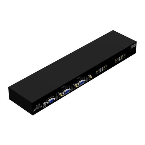
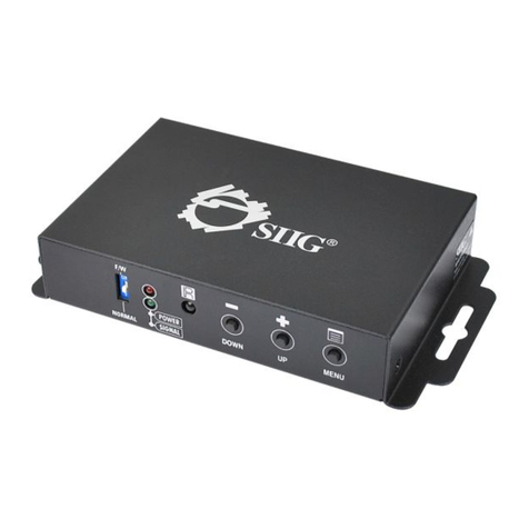
SIIG AV-GM0903-S1 User manual

Dual-View Video Processor
P/N: AV-GM0903-S1

Safety and Notice
The AV-GM0903-S1 Dual-View Video Processor has been tested for conformance to safety
regulations and requirements, and has been certified for international use. However, like all
electronic equipments, the AV-GM0903-S1 should be used with care. Please read and follow
the safety instructions to protect yourself from possible injury and to minimize the risk of
damage to the unit.
●Follow all instructions and warnings marked on this unit.
●Do not attempt to service this unit yourself, except where explained in this manual.
●Provide proper ventilation and air circulation and do not use near water.
●Keep objects that might damage the device and assure that the placement of this unit is on a
stable surface.
●Use only the power adapter and power cords and connection cables designed for this unit.
●Do not use liquid or aerosol cleaners to clean this unit. Always unplug the power to the
device before cleaning.
TABLE OF CONTENTS
INTRODUCTION.................................................................................................................1
FEATURES.........................................................................................................................1
PACKAGE CONTENTS......................................................................................................1
SPECIFICATIONS..............................................................................................................2
HARDWARE INSTALLATION.............................................................................................3
CONNECTION DIAGRAM ..................................................................................................3
PANEL DESCRIPTIONS.....................................................................................................4
OPERATION APPROACH..................................................................................................5
WARRANTY .....................................................................................................................19

1
INTRODUCTION
The AV-GM0903-S1 Dual-View Video Processor provides the most flexible and cost effective solution
in the market to route high definition video source from any of the two HDMI sources to the
remote display at the same time. This solution is well suited for use in home theater, conference
room presentation systems or other similar setting or application.
FEATURES
2 x Dual DVI inputs and 2 x Dual DVI outputs
Input resolutions support from 640x480 to 1920x1200, interlaced or progressive
Output resolutions support from 640x480 to 1920x1200, progressive
Adjustable size & position through software
The layouts are individual on the different output
Firmware upgradable for support of new features and technology enhancements.
Titles, borders and colored backgrounds
Resize, position, zoom& pan and blend output video
Perfectly as a video screen splitter, a video converter and a video switcher
Software control through RS-232 and Ethernet
Each dual output has an independently controllable area.
Supports input rotation.
1U size
PACKAGE CONTENTS
1x AV-GM0903-S1
1x DC 12V 5A
1x Installation software CD
1x User Manual
1x IR Remote control (28 keys)

2
SPECIFICATIONS
Model Name
AV-GM0903-S1
Technical
Role of usage
Multiplexer / video processor
Background video
input
No
HDCP compliance
HDCP 1.1
Video bandwidth
DVI [Single-link 4.95Gbps] HDMI [2.25G to 6.75Gbps]
Video support
480i / 480p / 720p / 1080i / 1080p60 /1920x1200@60 / 1600x1200@60
Video Format Support
DVI/HDMI
Audio support
No
Control
RS-232/ IP Control
Embedded video
mixer
Yes
Input TMDS signal
1.2 Volts [peak to peak]
ESD protection
Human body model —±15kV [air-gap discharge] & ±8kV [contact
discharge]
Input
2x DVI/HDMI + 2xRS-232 + 1x RJ-45(Ethernet)
Output
2x DVI
DVI connector
DVI-D [female, 29-pin]
RS-232 connector
DE-9 [9-pin D-sub female]
RJ-45 connector
WE/SS 8P8C
Mechanical
Housing
Metal enclosure
Dimensions
(L x W x H)
Model
290 x 211 x 43mm [11.4”x8.3”x1.7”]
Package
325 x 196 x 92mm [12.7”x7.7”x3.6”]
Carton
490 x 426 x 352mm [1’6”x1’4”x1’2”]
Weight
Model
2.9kg [6.4 lbs]
Package
5kg [11.1 lbs]
Fixedness
1RU rack-mount with ears

3
Power supply
12V 5A DC
Power Consumption
5.75 Watts [max]
Operation
temperature
0~40°C [32~104°F]
Storage temperature
-20~60°C [-4~140°F]
Relative humidity
20~90% RH [no condensation]
HARDWARE INSTALLATION
AV-GM0903-S1 as master
1. Connect all sources to DVI/HDMI Inputs on the AV-GM0903-S1.
2. Connect all display to DVI/HDMI Outputs on the AV-GM0903-S1.
3. Connect the +12V 5A DC power supply to the AV-GM0903-S1.
CONNECTION DIAGRAM

4
PANEL DESCRIPTIONS
Front Panel
1. Default Layout PAP: Default layout horizontal PAP/ vertical PAP
Horizontal PAP: The light of button 6 is off.
Vertical PAP: The light of button 6 is always shine.
2. Custom Layout 1-8
Custom layout 1-4: The light of button 6 is off.
Custom layout 5-8: The light of button 6 is always shine.
3. Source Selection Button: window in full screen or source selection window
Window in full screen mode: The light of button 6 is off.
Source selection: The light of button 6 is always shine.
4. IR Sensor: IR sensor for receiving the IR commands from IR remote
5. Chroma key: Chroma key function on/off
6. Function Selection
7. Rotation: Rotate function on/off
8. OSD: All Windows OSD on/off
Rear Panel
9. Power Switch: Power on/off
10. +12V DC: 12V DC power jack
11. RS-232: RS-232 control port
12. RS-232: RS-232 control port for F/W update
13. Ethernet: Ethernet control port
14. Dip Switch: Switch factory reset mode [ON↓]

5
15. Input 1-2: DVI inputs
16. Output: DVI output 2
17. Output: DVI output 1
18. USB 5V
OPERATION APPROACH
Method A: IR Remote Control
Button
Function
F1
Reserved
F2
Reserved
F3
Reserved
Power on/off the device
Chroma key
Chroma key function on/off
Label
Window label on/off
Default layout 1
Default layout 2
Custom layout 1
Custom layout 1
Custom layout 2
Custom layout 2
Custom layout 3
Custom layout 3
Custom layout 4
Custom layout 4
Custom layout 5
Custom layout 5
Custom layout 6
Custom layout 6
Custom layout 7
Custom layout 7
Custom layout 8
Custom layout 8
Full screen layout 1
Window 1 in full screen
Full screen layout 2
Window 2 in full screen
Full screen layout 3
Window 3 in full screen
Full screen layout 4
Window 4 in full screen
Source selection 1
Window 1 source selection
Source selection 2
Window 2 source selection
Source selection 3
Window 3 source selection
Source selection 4
Window 4 source selection

6
Method B: Software Control through RS-232 port / Ethernet port
System Requirement and Precautions
1. Whenever power off AV-GM0903-S1, please stay unpowered at least 5 to 10 seconds to allow
power capacitors to discharge.
2. The AV-GM0903-S1 provides software control program which runs under Microsoft Windows 98,
2000, XP, 7, 8 through the interface of RS-232 serial control.
3. Before you click on the icon of the software, make sure you have secured the connection
between your computer COM port and the AV-GM0903-S1.
Start the software control program
When clicking on the executable file, the following dialog will pop-up. It has two ways to control the
AV-GM0903-S1 device (under Microsoft Windows 7, please run as administrator).
RS-232 serial Mode: Use RS-232 to connect the port on device and computer. Select correct COM
port and click the connect button.
TCP/IP Mode: Enter the device IP address and click the connect button.
After the software control setting is accomplished, it will enter directly to control interface.

7
Control Interface
1. PAP Panel
Display and adjust the window size, position.
In this part, it has the different control tool for PAP panel setting.
Control percent: 10~100% to set the PAP Panel display/control
size.
Stretch: Fix the size ratio when the window is resizing.
Background picture: To set up the background picture of
window.
Window priority
PAP mode
Window 1 in full screen
Window 2 in full screen
In addition, you can change the output layout by clicking the mouse left button. It has four
different layouts (Dual Horizontal Output, Dual Vertical Output, Single Output 1, and Single
1
2
3
4
5
6

8
Output 2).
2. Tool Bar list:
(1) Status: Get all information of the device and update this software state.
(2) Port Setting: Pop-up the “Port Setting” dialog, user can change the connecting way.
(3) Advance Setting: In this function, user can set the no signal color, fade in/out effect,
output control, background picture, window text, input text, OSD border, rotation, EDID
and factory reset.

9
Output Control Setting:
In this function, user can determine to turn on or off the HDMI mode and audio, and
also can select the configuration of background picture.
Rotation:
For Rotation function, only window 1 can be applied.

10
.

11
EDID:
User can learn EDID from default or display. In addition, it also provides advance EDID
function for user to edit, save and read.

12
Factory Reset:
Click the button to do factory default reset. This default reset
process will take about 10~15 seconds and it will be initialized all setting to original
system state.
(4) Chroma Key: It can turn on/off the Chroma key function and adjust the parameters
of Chroma key.

13
(5) Crop function: This function is used to crop or clip an image.
In the Preview Crop, it can preview the range and effect of video crop with the adjustment.
Crop Enable: Enable crop function
Array Enable: Enable array parameter
The setup diagram is shown as below.

14
Percent Enable: Allows user to adjust video layout size by percentage concept.
The setup diagram is shown as below.
Pixel Enable: Allow user to adjust video layout size by pixels.
The video crop by pixel and percent are almost same. The differences come from the
adjustment ratio.
(6) Version: Read the software and firmware version.

15
3. Output Resolution:
Set the output resolution. When setting the different resolutions, the parameters of PAP and
custom layout (position and size) will accordingly change.
4. Default layout and Custom layout:
Default layout: Use factory preloaded video layouts.
Custom layout: Use custom pre-saved video layouts
In this part, you can adjust the size and position of output screen. If you want to save
the layout, please click the right button of mouse to save this layout into device.

16
5. Window selection and input mapping
For each display window, user can assign arbitrary video input here.
6. Window setting
In here, you can adjust the size, position or other settings of the specified window.

17
Method C: Firmware Update
1. Unfold the Video Processor folder and choose the firmware update executable file. The
firmware update window shows up as below.
2. Please select the correct COM port or click button to connect the device.
3. Click button to do firmware update.

18
4. If you want to change OSD (window label) font, please click “OSD Font Update” window and click
button to change OSD font.
5. If you want to change the boot screen, please click “Splash Screen Update” window and click the
button to select the graph which you want to write into the device.
Table of contents
Other SIIG Media Converter manuals

SIIG
SIIG CE-SD0811-S1 User manual

SIIG
SIIG JU-HS2012-S4 User manual

SIIG
SIIG AV-GM01Q3-S1A User manual

SIIG
SIIG CE-H21Z11-S1 User manual

SIIG
SIIG CE-HM0031 User manual

SIIG
SIIG CE-H24L11-S1 User manual

SIIG
SIIG CE-H20511-S1 User manual

SIIG
SIIG AV-GM0A73-S1 User manual

SIIG
SIIG CE-DV0031-S1 User manual

SIIG
SIIG RS-232 to Multi-Mode Fiber Optic User manual

SIIG
SIIG AV-GM01Q3-S1DS User manual

SIIG
SIIG AV-GM08W3-S1 User manual
SIIG
SIIG CV-005B User manual

SIIG
SIIG ID-SB0011-S1 User manual

SIIG
SIIG AV-GM0A43-S1 User manual

SIIG
SIIG CE-H23L11-S1 User manual

SIIG
SIIG AV-GM04R3-S1-TX User manual

SIIG
SIIG AV-GM08X3-S1 User manual

SIIG
SIIG FE-CXST11 User manual
SIIG
SIIG AV-GM08S3-S1 User manual