SIKA Induq VMM Series User manual

Please keep this operating manual for future reference.
If the device is resold, please provide the operating manual along with it.
© SIKA •Ba_VMM_us •09/2018 .
Magnetic Inductive
Flow Sensor
Series VMM
Operating manual
Operating manual
................................................... page 1 - 56

induQ®- Series VMM
- 2 - © SIKA •Ba_VMM_us •09/2018
Table of contents page
0About this operating manual.........................................................................................4
1Device description .........................................................................................................5
1.1 Delivery, unpacking and accessories .........................................................................6
1.2 Intended use................................................................................................................7
1.3 Exclusion of liability ....................................................................................................7
2Safety instructions.........................................................................................................8
3Construction and function.............................................................................................9
3.1 Construction................................................................................................................9
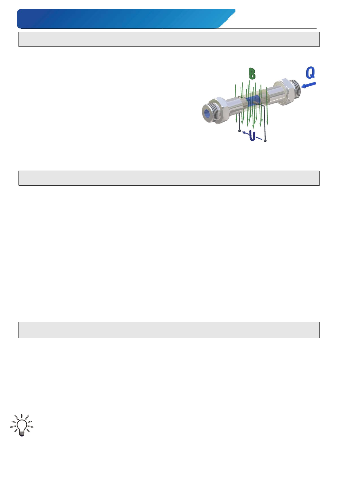
3.2 Measuring principle ..................................................................................................10
3.3 Functions...................................................................................................................10
4Installation of VMM......................................................................................................10
4.1 Installation instructions display electronics ............................................................11
4.2 Instructions on potential equalization and cathode protection................................12
4.2.1 Potential equalization ...........................................................................................12
4.2.2 Cathodic protectives .............................................................................................13
4.3 Sensor installation instructions................................................................................14
4.4 Mounting....................................................................................................................16
5Electrical connection...................................................................................................17
5.1 Mains and signal cable..............................................................................................17
5.2 Electrode and magnetic current line........................................................................19
6Commissioning............................................................................................................19
7Operation .....................................................................................................................21
7.1 Functional classes (main menu)...............................................................................24
7.1.1 Measured values...................................................................................................25
7.1.2 Password ..............................................................................................................27
7.1.3 Totalizer ................................................................................................................29
7.1.4 Measurement processing.....................................................................................30
7.1.5 Flow.......................................................................................................................31
7.1.6 Pulse output..........................................................................................................34
7.1.7 Status output.........................................................................................................36
7.1.8 Current output ......................................................................................................37
7.1.9 Simulation .............................................................................................................38
7.1.10 Self-test ................................................................................................................40
7.1.11 Settings Sensor.....................................................................................................42
8Errors and returns ......................................................................................................46
8.1 System errors............................................................................................................46
8.2 Self-test errors .........................................................................................................47
8.3 Return shipment to the manufacturer .....................................................................48

induQ®- Series VMM
Technical changes reserved - 3 -
9Cleaning, maintenance, storage .................................................................................49
9.1 Cleaning.....................................................................................................................49
9.2 Maintenance ..............................................................................................................49
9.3 Storage ......................................................................................................................50
10 Disassembly and disposal...........................................................................................50
11 Technical data..............................................................................................................51
11.1 Characteristics of the VMM.......................................................................................51
11.2 Materials table ..........................................................................................................53
11.3 Dimensions and weights ...........................................................................................54
11.3.1 Compact device.....................................................................................................54
11.3.2 Separate version (with wall bracket)....................................................................55
induQ®
is a registered trademark of SIKA Dr. Siebert & Kühn GmbH & Co. KG.
Copyright notice:
The reproduction, distribution and utilization of this operating manual as well as the communication of
its contents to others without express authorization is prohibited. Offenders will be held liable for the
payment of d
amages. All rights reserved in the event of the grant of a patent, utility model or design.

About this operating manual induQ®- Series VMM
- 4 - © SIKA •Ba_VMM_us •09/2018
0About this operating manual
•The operating manual is aimed at specialists and semi-skilled personnel.
•Before each step, read through the relevant advice carefully and keep to the specified
order.
•Thoroughly read and understand the information in the section "Safety instructions".
If you have any problems or questions, please contact your supplier or contact us directly at:
SIKA USA Inc.
1500 S. Sylvania Ave. • Suite 111
Sturtevant • WI 53177
262 886-2695 • 262 898-0101
info@sika-usa.com • www.sika-usa.com
Hazard signs and other symbols used:
DANGER! Danger to life due to non-observance!
This sign indicates dangers which could lead to serious health defects or to death.
WARNING! / CAUTION! Risk of injury!
This sign indicates dangers that cause personal injuries that can lead to health defects or
cause considerable damage to property.
CAUTION! Electric current!
This sign indicates dangers which could arise from handling of electric current.
CAUTION! High temperature!
This sign indicates dangers resulting from high temperature that can lead to health defects or
considerable damage to property.
CAUTION! Material damage!
This sign indicates actions which could lead to possible damage to material or environmental
damage.
ADHERE TO OPERATING MANUAL!
NOTICE!
This symbol indicates important notices,
tips or information.
NO DOMESTIC WASTE!
The device must not be disposed of to-
gether with domestic waste.
Pay attention to and comply with infor-
mation that is marked with this symbol.
Follow the specified instructions and steps.
Adhere to the given order.
Check the specified points or notices.
Reference to another section, document or
source.
•Item.

induQ®- Series VMM Device description
Technical changes reserved - 5 -
1Device description
The induQ®of the VMM from SIKA is a flow sensor without moving parts. The measurement
is performed using magnetic induction.
The VMM is used for measuring or dosing water and electrically conductive fluids. The com-
plete measuring instrument comprises the sensor and the related display electronics.
The display electronics is microprocessor controlled and programmable. It can be custom-
ized using a control unit.
The basic configuration settings such as display electronics calibration are realized at the
factory. Other settings are user definable.
Measurement data from sensors are processed by display electronics. It is designed for flow
velocities up to 33 ft/s (10 m/s).
Components:
The most important components of the VMM are
Display electronics.
Indication and control panel.
Sensor.
Measuring tube.
Junction box.
Process connection.
Versions:
The VMM is available as a compact device
(Fig. left) or in separate design (Fig. right).
Both designs are available with inner diameters from 1 ¼" to 8" with different features.
Type plates:
The type plates you can find at the backs of evaluation electronics and sensor.
They contain the most important technical data of VMM.

Device description induQ®- Series VMM
- 6 - © SIKA •Ba_VMM_us •09/2018
1.1 Delivery, unpacking and accessories
All units have been carefully checked for their operational reliability before shipment.
Immediately after receipt, please check the outer packaging for damages or any signs of
improper handling.
Report any possible damages to the forwarder and your responsible sales representative.
In such a case, state a description of the defect, the type and the serial number of the de-
vice.
Report any in-transit damage immediately. Damage reported at a later date shall not be
recognized.
Unpacking:
Carefully unpack the unit to prevent any damage.
Check the completeness of the delivery based on the delivery note.
Scope of delivery:
1x VMM according to the order data.
1x operating manual.
certificates (optional)
IMPORTANT!
Use the type plate to check if the delivered unit corresponds to your order.
In particular, for devices with electrical components, check to see if the correct pow-
er supply voltage is specified.
Accessories:
Installation supplies (gaskets/seals, screws, etc.) are not included with the delivery.
Grounding rings.
Protection rings.
Sensor cable.
You can find details on the accessories in our catalog on the Internet.

induQ®- Series VMM Device description
Technical changes reserved - 7 -
1.2 Intended use
Magnetic inductive flow sensor VMM is only intended to be used for measuring and dosing /
batching the flow of electric conductive, liquid media
According to the Pressure Equipment Directive 2014/68/EU, only Group 2 fluids are permitted
to be used.
Due to the magnetic field, the device can be used to measure flow rates up to 33 ft/s (10 m/s)
and a minimum conductivity of 50 μS/cm, when using a synchronized static field.
WARNING! No safety component!
The flow sensor of the series VMM is not a safety component in accordance with Di-
rective 2006/42/EC (Machine Directive).
Never use the VMM as a safety component.
The operational safety of the device supplied is only guaranteed by intended use. The speci-
fied limits (§ 4.3 "Sensor installation instructions") may under no circumstances be ex-
ceeded.
Before installing the device, check if the wetted materials of the device are compatible with
the media being used (§ 11.2 "Materials table").
CAUTION! Risk of injury due to high temperature!
Hot process media can lead to hot surfaces! Danger of burns with surface temperatures
above 158 °F (70 °C).
Take suitable protective measures, e.g. contact protection.
The contact protection must be devised so that the maximum ambient temperature on
the device is not exceeded.
Flow tube empty (partially filled). / Conductivity too low:
Faulty measurements can occur if the flow tube of the VMM is empty or partially filled or
if the conductivity of the fluid being used is too low.
Make sure that the flow tube of the VMM is always completely filled
(§ 4.3 "Sensor").
Please observe the function "Empty pipe detection" (p. 10).
Make sure that the fluid being used has a conductivity of at least 50 μS/cm.
Before ordering and installing, check that the device is suitable for your application.
1.3 Exclusion of liability
We accept no liability for any damage or malfunctions resulting from incorrect installation,
in-appropriate use of the device or failure to follow the instructions in this operating manual.

Safety instructions induQ®- Series VMM
- 8 - © SIKA •Ba_VMM_us •09/2018
2Safety instructions
Before you install the VMM read through this operating manual carefully. If the instruc-
tions contained within it are not followed, in particular the safety guidelines, this could
result in danger for people, the environment, and the device and the system it is con-
nected to.
The VMM corresponds to the state-of-the-art technology. This concerns the accuracy, the
operating mode and the safe operation of the device.
In order to guarantee that the device operates safely, the operator must act competently and
be conscious of safety issues.
SIKA provides support for the use of its products either personally or via relevant literature.
The customer verifies that our product is fit for purpose based on our technical information.
The customer performs customer- and application-specific tests to ensure that the product
is suitable for the intended use. With this verification all hazards and risks are transferred to
our customers; our warranty is not valid.
Qualified personnel:
The personnel who are charged for the installation, operation and maintenance of the
VMM must hold a relevant qualification. This can be based on training or relevant tuition.
The personnel must be aware of this operating manual and have access to it at all times.
The electrical connection should only be carried out by a fully qualified electrician.
General safety instructions:
In all work, the existing national regulations for accident prevention and safety in the
workplace must be complied with. Any internal regulations of the operator must also be
complied with, even if these are not mentioned in this manual.
Degree of protection according to EN 60529:
Ensure that the ambient conditions at the site of use does not exceed (comply with) the
requirements for the stated protection rating (§ 11.1 "Characteristics of the VMM").
Take appropriate measures to ensure that the medium does not freeze.
Only use the VMM if it is in perfect condition. Damaged or faulty devices must be checked
without delay and, if necessary, replaced.
When fitting, connecting and removing the VMM use only suitable, appropriate tools.
Do not remove or obliterate type plates or other markings on the device, as otherwise the
warranty is rendered null and void.

induQ®- Series VMM Construction and function
Technical changes reserved - 9 -
Special safety instructions:
Danger! Electric current!
Particular care must be taken if the front window of the housing becomes fogged over or
discolored because moisture, water or product might seep through the wire sheath into
the terminal compartment in the housing!
Ingress protection IP67 is only achieved if suitable and tightly screwed down cable glands
or conduits are used. If the cable glands are only tightened manually water may leak into
the terminal compartment in the housing.
Electromagnetic compatibility is only achieved if the electronics housing is closed. Leav-
ing the enclosure open can lead to electromagnetic disturbances.
Further warnings that are specifically relevant to individual operating procedures or activities
can be found at the beginning of the relevant sections of this operating manual.
3Construction and function
3.1 Construction
The VMM comprises a sensor and the display electronics. The sensor is used to measure flu-
id media. The display electrodes generate the coil current required for the magnetic field and
prepares the induced voltage applied to the electrodes.
The VMM does not need any moving parts to make measurements. The inside
of the measuring tube is completely open, allowing the fluid to flow unhin-
dered through the measuring tube.
Display electronics:
The display electronics has a backlit LCD.
6 buttons are used for operation. That facilitates easy
configuration of the display electronics.
Furthermore the display electronics has an analog
0/4 … 20 mA current output, a pulse or frequency out-
put and a status output.

Installation of VMM induQ®- Series VMM
- 10 - © SIKA •Ba_VMM_us •09/2018
3.2 Measuring principle
The magnetic inductive flow sensor operates on the inductive principle, i.e., a direct current
is generated by the movement of a conductor in a magnetic field:
The measuring pipe of the VMM is in a magnetic
field (B).
An electrically conductive medium (Q) passes through
the pipe. During this, the positive and negative load car-
riers are inversely deflected.
A voltage arises which is perpendicular to the magnetic
field, which is tapped through both electrodes.
The voltage induced during this is proportional to the
average flow velocity of the fluid.
The electronics of the VMM converts the induced voltage into a flow-proportional frequency
signal.
3.3 Functions
Empty pipe detection:
The electronic display unit has the ability for an empty pipe detection, which can be activated
and deactivated.
The operating reliability depends on the conductivity of the liquid medium and the cleanliness
of the electrodes.
As higher the conductivity is, as more reliable operates the empty pipe detection.
Insulation coatings on the electrodes surface worse the empty pipe detection.
Safety of operation:
A comprehensive self-monitoring system ensures maximum safety of operation.
•Potential errors can be reported immediately via the configurable status output. The
corresponding error messages will also be displayed on the display of the display elec-
tronics. A failure of the auxiliary power can also be detected via the status output.
•All outputs are electrically isolated from the auxiliary power, the sensor circuit and from
each other.
4Installation of VMM
Before installing, check that
the wetted materials of the device are suitable for the liquid being used
(§ 11.2 "Materials table").
the equipment is switched off and is in a safe and de-energized state.
the equipment is depressurized and has cooled down.
Please observe in particular "Instructions on potential equalization and cathode protec-
tion" (§ 4.2).
Suitable tools:
Use only suitable tools of the correct size.

induQ®- Series VMM Installation of VMM
Technical changes reserved - 11 -
4.1 Installation instructions display electronics
Compact version (standard):
For the compact version the display electronics housing is mounted on the sensor. Therefore
no cable is necessary between sensor and display electronics.
Remote version (optional):
The display electronics needs to be mounted separately from the sensor if:
•the mounting area is difficult to access or there is a lack of space,
•medium and ambient temperatures are extremely high,
•there is strong vibration.
The display electronics has to be mounted free of vibrations!
Make sure that the cables are properly installed at high humidity
and wet conditions.
The electrode cable must be fixed. If the conductivity of the medium
is low, cable movements may change the capacity considerably and
thus disturb the measuring signal.
Do not lay the cables close to electrical machines and switching elements.
Equipotential bonding must be ensured between sensor and display electronics.
IMPORTANT! Pay attention to the maximum cable
length!
For the separate version, the minimum permissi-
ble conductivity of the medium is determined by
the distance between the sensor and the display
electronics.
The maximum cable length to ensure accuracy is
656 ft (200 m) (p. 17 "Connecting cables").

Installation of VMM induQ®- Series VMM
- 12 - © SIKA •Ba_VMM_us •09/2018
4.2 Instructions on potential equalization and cathode protection
4.2.1 Potential equalization
The signal outputs (process outputs and the mains supply of the VMM are galvanic isolated
from each other. The housing and the interference filter of the mains supply are connected to
PE.
The electrodes and measuring electronics are related to the potential of the function ground
FE of the sensor. FE is not connected to PE, but may be connected with each other in the
sensor junction box. If the sensor is grounded by using ground disks (grounding rings), these
must in connected with the function ground FE.
At a separate assembly of sensor and display electronics the outer screen of the connecting
cable is connected to the housing of the display electronics and has PE potential. The inner
screens of the electrode line are connected to FE inside the junction box of the sensor and to
the mass (GND) of the display electronics.
Details of all wirings, terminals and drawing can be found in § 5 "Electrical connection".
IMPORTANT!
The display electronics can only process the measuring signal interference-free if this
voltage is referenced to a fixed potential (ground).
Potential equalization on electrically conductive
pipes:
The sensor is electrically connected to the pipe-
line in the sense of a potential equalization.
Thus, the pipeline is grounded, and the media and
therefore the signal voltage have a solid signal
common.
Potential equalization on electrically insulated pipes:
When using pipes lined with electrical insulation,
plastic tubing or concrete conduits, a separate
grounding washer is used to ground the measur-
ing media. The grounding washer is installed be-
tween the pipeline connection and the sensor’s
flange and the ring’s inside contacts the media.
Contrary to the diagram shown below, one
grounding washer on the inflow side is sufficient.
If bidirectional measurements are to be taken,
one grounding washer must be installed on either
side.
Protection washers or protection rings can also be used as grounding component; or special
grounding electrodes, incorporated in the sensor, may be installed.
Grounding electrodes are more economical than grounding washers. However, it must be
ensured that noticeable differences in potential within the equipment are eliminated, other-
wise the grounding electrodes will electrolyze and be destroyed.

induQ®- Series VMM Installation of VMM
Technical changes reserved - 13 -
Potential-free installation of the sensor:
If the pipelines cannot be grounded, due to operational reasons, the sensor must be installed
voltage free. To do this, a separate cable must be used to electrically connect these seg-
ments of the pipeline (min. 11.8 kcmil (6 mm²)).
An electrical connection occurring between the sensor and any material used for the instal-
lation must be avoided. Insulating segments must be installed between the sensor and the
pipeline (e.g. PVC pipes or similar).
Subsequently, grounding washers are used to electrically connect the media with the display
electronics. The display electronics must not be connected with the protective ground con-
ductor. This may only be done, if the auxiliary power is 24 VDC.
Potential equalization in separate design:
Create the potential equalization in the separate design the same as described in the above
sections. For the potential equalization, the display electronics and the sensor are connected
to each other through Pin 7 of the connecting cable.
4.2.2 Cathodic protectives
Using a cathodic protective unit to avoid corrosion, which put a voltage to the tube wall, it
must be connected to terminal FE. The boards, control panel and internal switches of the
display electronics are on the same potential as FE.
CAUTION! Electric current - comply with limits!
According to EN 61010-1:2012 all electrical circuits with „protective safety isolation with-
out any protection against contacts” must observe the following maximum voltages:
•Maximum AC voltage (Veff) 33 V
•Maximum DC voltage 60 V.
Make sure that no higher potential is connected to FE.

Installation of VMM induQ®- Series VMM
- 14 - © SIKA •Ba_VMM_us •09/2018
4.3 Sensor installation instructions
CAUTION! Risk of malfunction due to external magnetic fields!
Magnetic fields close to the device can cause malfunctions and
should be avoided.
Ensure that no external magnetic fields are present at the in-
stallation site of the VMM.
Please observe § 1.1 "Delivery, unpacking and accessories" and the following installation in-
structions:
General:
•The VMM can always be installed at any point on the pipeline in the horizontal as well as
in vertical sections.
Ideally, the sensor should be installed in a pipeline with a sufficient straight run, both be-
fore and after the measuring point.
•Basically, the measuring principle does not depend on the flow profile. You should use
straight inlet and outlet sections according to the inner diameter (ID). An inflow path of
5 x ID and an outflow zone of at least 2 to 3 x ID is required.
•The flow sensor is only suitable for application in completely filled pipe systems. With a
free pipe outlet, the sensor should not be installed in pipe sections that could run empty
(e.g., downpipes).

induQ®- Series VMM Installation of VMM
Technical changes reserved - 15 -
If the sensor must be installed in a down pipe, ensure that portion of the pipeline is al-
ways filled 100% with the media.
•Due to possible accumulation of gases, the sensor should not be installed at the highest
point of a pipeline.
•It must be ensured, that the axes of the electrodes are running
horizontally to avoid erroneous measurements due to deposits or
air bubbles on the electrodes.
Also, note that in case of deviations from horizontal, the function-
ing of the Empty pipe detection (p. 10) is limited.
Installation in unfilled pipeline:
•If a pipeline is not always filled, or in case of
an open channel (drainage), the sensor must
be installed in a siphon. That means the flow
tube cannot run dry and is always filled with
measured medium.
Installation between tees, valves and pumps:
Always maintain the distance of the pipe's straight run. If these distances cannot be main-
tained, flow conditioners must be installed or pipes with smaller diameter must be used.
If several sensors are installed in series, the distance between each sensor must be equal to
the length of one sensor. If two or more sensors are to be installed in parallel, the distance
between sensors must be at least 3.3 ft (1 m).

Installation of VMM induQ®- Series VMM
- 16 - © SIKA •Ba_VMM_us •09/2018
Measures during malfunctions:
In case of malfunctions in the inflow section due to vortexing (e.g. after pipe elbows, at tan-
gential inclusions or with a half-open gate before the sensor), measures for normalization of
the flow profile are necessary.
The appropriate steps are:
•increasing the inflow and outflow zones
•using flow conditioners
•reducing the inner diameter of the pipe
4.4 Mounting
As a compact device, the VMM is installed directly into the pipeline. With the separate design,
the sensor is installed in the pipeline. The display electronics can be attached to the wall with
the bracket.
IMPORTANT NOTICES:
•Only use suitable gaskets for installation.
•Observe the flow direction indicated on the type plate and
on the back site of the sensor.
•Observe the mounting dimensions (§ 11.3 “Dimensions
and weights”).
Select an appropriate location for installation
(§ 4.3 "Sensor installation instructions").
To ensure the best possible measuring accuracy, a vertical
installation position with increasing flow is preferable (no col-
lecting of dirt deposits).
Install the appropriate screwed connections at the installa-
tion location.
Insert the VMM together with the gaskets.
Connect the flange connections corresponding to the re-
quirements of their use.
WARNING! Risk of injury or material damage!
Incorrect gaskets and connection materials plus improper assembly can lead to injuries
or material damage.
During installation, comply with the requirements that result from your application.
Maintain the required tightening torques.
IMPORTANT! Weather protection required
In the case of an outdoor installation, the device must be protected against direct solar
irradiation with a weather shield.

induQ®- Series VMM Electrical connection
Technical changes reserved - 17 -
5Electrical connection
CAUTION! Electric current!
The electrical connection of the VMM should only be carried out by a fully qualified elec-
trician.
De-energize the electrical system before connecting the VMM.
Make the electrical connection of the VMM through the terminal strips in the interior of the
display electronics.
For the separate design, the sensor cable for the electrodes and the magnetic current are
required in addition. They are connected through the terminal strips in the junction boxes of
the display electronics and the sensor.
Connecting cables:
When connecting the VMM, use the following cable depending on the cable lengths:
Cable length
Wire cross-section
Example
Cable ends dimension:
≤ 32,8 ft (10 m) ≥ 0.5 kcmil (0.25 mm2) LIYCY-CY TP 2x2x0.25 mm2
> 32,8 ft (10 m) ≥ 1.5 kcmil (0.75 mm2) LIY-TPC-Y 2x2x0.75 mm2
The cables are each twisted in pairs and shielded. In order to protect the cable from external
interference, the pair wires are covered by an additional, overall shield.
The outer shield is grounded by means of special EMC-compliant
cable glands at both ends of the cable.
IMPORTANT! Potential equalization required!
Comply with the instructions on Potential (§ 4.2.1).
5.1 Mains and signal cable
The connection of the mains and signal cable are the same in both versions.
The terminal strips are located behind the rear hous-
ing cover.
Screw the rear cover from the housing counter
clockwise.
Only use signal cables as specified in chapter
"Connecting cables“.
Lay the signal cables separately from cables with
voltages >60 V.
Avoid laying signal cables close to large electrical installations.
IMPORTANT! Pay attention to the clamping area of the cable gland!
To guarantee the protection class as per DIN EN 60529, the connection cable being used
must have a sheathing diameter that matches the cable gland.

Electrical connection induQ®- Series VMM
- 18 - © SIKA •Ba_VMM_us •09/2018
Terminal assignment:
Terminal Label Function
115 / 230 V
AC
24 V
AC
1 PE Protective conduc-
tor -/-
2 N Neutral conductor 0 V
3 L Phase 24 V
4 Pulse - Pulse output (passive)
5 Pulse +
6 Status - Status output (passive)
7 Status +
8 Current - Current output
(active / passive)*
9 Current +
* permanently configured in factory.
Wiring pulse / status output (passive):
The external wiring for the pulse output and the status output is the same.
The wiring for the pulse output is done via terminals 4 and 5 and for the status output via
terminals 6 and 7.
Pull-up wiring:
Pull-down wiring:
Switching values:
UN: 24 V
Umax: 30 V
Imax: 60 mA
Pmax: 1.8 W
Recommendation Pull-Up / Pull-Down resistance ~5 kΩ.
Wiring current output (passive):
An external voltage supply is required when connecting the passive current output.

induQ®- Series VMM Commissioning
Technical changes reserved - 19 -
5.2 Electrode and magnetic current line
For the separate design, the electrodes and magnetic current cable must be connected in
addition.
CAUTION! Electric current!
Do not connect or disconnect the field coil cable
before the primary power of the meter has been
disconnected!
Connect through the terminal strips in the junction
boxes of the display electronics and the sensor.
Pin assignment:
Terminal
Wire color Function
Magnetic current line (3 wire)
5 brown Magnetic field current 1
6 white Magnetic field current 2
7 green-yellow Potential equalization / PE
Electrode line (5 wire*)
22 red Measuring ground
23 brown Electrode 1
24 white Electrode 2
* The wires green-yellow and blue are not connected.
Only use cables as specified in chapter
"Connecting cables“.
The outer shield is grounded by means of special
EMC-compliant cable glands at both ends of the
cable.
The inner shields are connected to terminal 7 and 22 respectively.
6Commissioning
Before switching on the VMM for the first time, please observe the following instructions.
Check that
the VMM has been installed correctly and that all screw connections are sealed.
the electrical wiring has been connected properly.
the measuring system is vented by flushing.
Startup conditions:
The device is not subject to specific startup conditions. However, pressure surges should be
avoided.

Commissioning induQ®- Series VMM
- 20 - © SIKA •Ba_VMM_us •09/2018
Change the orientation of the display electronics (only compact version)
The display electronics of the compact version isn't
rigidly connected to the sensor but can be turned by
± 180°.
The display electronics has been factory-installed so
that in case of a horizontal piping and a flow direction
from left to right the set orientation is in the correct
position.
Follow the steps to change the orientation of the dis-
play electronics:
Loosen the two setscrews .
Turn the display electronics in the desired posi-
tion.
Tighten the two setscrews again.
This manual suits for next models
2
Table of contents
Other SIKA Accessories manuals

SIKA
SIKA VT 15 Series User manual

SIKA
SIKA Turbotron VTM25 User manual

SIKA
SIKA induQ VMI Series User manual

SIKA
SIKA VT 25 Series User manual

SIKA
SIKA VVX User manual

SIKA
SIKA induQ VMI Series User manual

SIKA
SIKA VTR Series User manual

SIKA
SIKA VVX Series User manual

SIKA
SIKA VTY10MA User manual

SIKA
SIKA INDUQ VMI 07 User manual