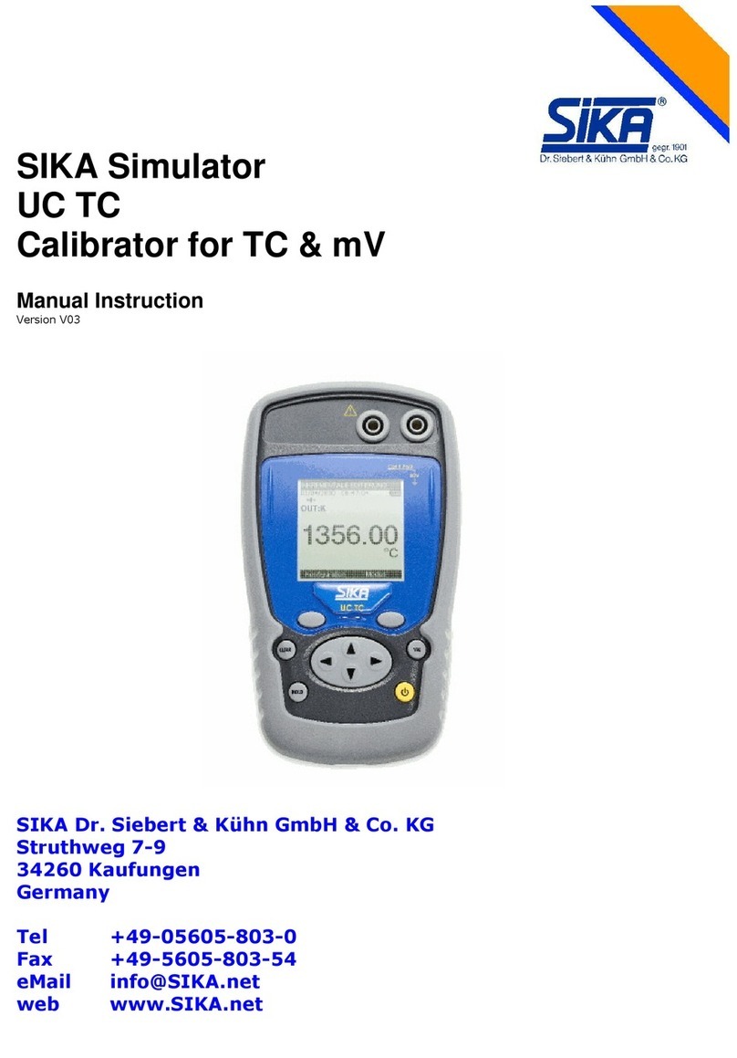
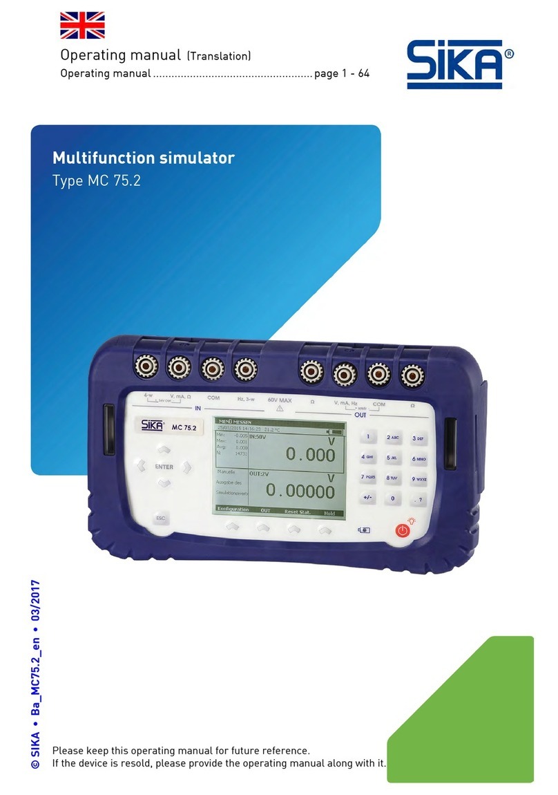
SIKA Simulator UC mAV User manual

SIKA Simulator
UC mAV
Calibrator for mA & V
Instruction Manual
version V01
SIKA Dr. Siebert & Kühn GmbH & Co. KG
Struthweg 7-9
34260 Kaufungen
Germany
Tel +49-05605-803-0
Fax +49-5605-803-54
eMail info@SIKA.net
web www.SIKA.net

SIKA Dr. Siebert & Kühn GmbH & Co. KG, Struthweg 7-9, 342 0 Kaufungen, Germany 2/33
Acknowledgements
Thank you for choosing this SIKA precision measuring instrument, which incorporates our extensive
experience in the manufacture of precision measuring appliances, which spans over more than a century.
We are thus able to continue our policy of constant innovation which has served our customers so well for
more than 100 years. SIKA welcomes any comments or suggestions you might have to enable us to
perfect our know-how and make our future products even better.
LIMIT OF WARRANTY AND LIABILITY
SIKA guarantees this product against defective materials and faulty manufacture under normal conditions
of use and maintenance. The warranty lasts one year and takes effect on the date of shipping. Parts,
repairs to the product and services are guaranteed for 90 days. This warranty only applies to the original
purchaser or the end-user if the end-user is the customer of an SIKA-approved distributor, and it does not
apply to the fuses, interchangeable batteries or any product which, in the opinion of SIKA, has been
handled roughly, modified, neglected, damaged accidentally or subjected to abnormal utilization and
handling conditions. SIKA guarantees that the software will function largely in accordance with its
functional specifications for a period of 90 days and that is has been correctly recorded on non-defective
media. SIKA does not guarantee that the software contains no errors or that it functions without
interruption.
SIKA-approved distributors shall apply this warranty to new and unused products sold to their customer,
but they are not authorized to apply a more extensive or a different warranty in the name of SIKA. The
warranty support is offered if the product has been purchased through an SIKA-approved point of sale or if
the purchase has paid the applicable international price. SIKA reserves the right to bill the purchaser for
the costs of importing repair or replacement parts if the product purchased in a given country has been
sent to another country for repair.
The warranty commitment of SIKA is limited, at the choice of SIKA, to reimbursement of the purchase
price or the repair/replacement free of charge of a defective product returned within the warranty period to
a servicing centre approved by SIKA.
If you wish to apply invoke the warranty, contact the nearest SIKA agency or send the product along with a
description of the problem, carriage and insurance paid (free to shipping destination), to the nearest SIKA-
approved servicing centre. SIKA declines all responsibility for damage incurred in transport. After repair
under warranty the product will be returned to the purchaser, carriage expenses paid in advance (free to
shipping destination). If SIKA judges that the problem has been caused by mistreatment, a modification,
an accident of abnormal operating or handling conditions, SIKA will submit a quotation for the cost of
repair and will not begin the repair until it has been authorized to do so. After repair, the product will be
returned to the purchaser, carriage expenses paid in advance, and the costs of repair and carriage will be
invoiced to the purchaser.
THIS WARRANTY IS EXCLUSIVE AND REPLACES ALL OTHER WARRANTIES, WHETHER EXPLICIT
OR IMPLICIT, INCLUDING, BUT NOT EXCLUSIVELY, ANY IMPLICIT WARRANTY CONCERNING THE
FITNESS OF THE PRODUCT TO BE SOLD OR USED FOR A PREDETERMINED PURPOSE OR USE.
SIKA SHALL NOT BE HELD RESPONSIBLE FOR ANY SPECIFIC, INDIRECT OR ACCIDENTAL OR
SUBSEQUENT DAMAGE OR LOSS OF DATA, WHETHER FURTHER TO INFRINGEMENT OF THE
WARRANTY OBLIGATIONS, ON A CONTRACTUAL, NON-CONTRACTUAL OR OTHER BASIS.
Given that certain countries or states do not accept the limitations of an implicit warranty condition, or the
exclusion or limitation of accidental or subsequent damage, the limitations and exclusions of this warranty
may not apply to each buyer. If any provision of this warranty is considered invalid or inapplicable by a
competent court, such a decision will in no way affect the validity or enforceable nature of any other
provision.

SIKA Dr. Siebert & Kühn GmbH & Co. KG, Struthweg 7-9, 342 0 Kaufungen, Germany 3/33
Tel +49-5 05-803-0, Fax +49-5 05-803-54, eMail info@SIKA.net, web www.SIKA.net
Verification of content
The SIKA UC mAV has been mechanically and electrically verified before shipping. The necessary
precautions have been taken for it to reach the user undamaged.
It is nevertheless wise to make a quick check for any damage that might have been incurred in transport. If
such is the case, immediately make the usual reservations with carrier.
The following standard accessories are supplied:
•This user's manual
•Four 1.5V AA batteries
•A wrist-strap
•A protective sheath
•2 test leads
•2 croco clips
In case of return shipping, it is preferable to use the original packaging and to indicate the reasons for
returning the instrument as clearly as possible in a note enclosed with the instrument.

SIKA Dr. Siebert & Kühn GmbH & Co. KG, Struthweg 7-9, 342 0 Kaufungen, Germany 4/33
Tel +49-5 05-803-0, Fax +49-5 05-803-54, eMail info@SIKA.net, web www.SIKA.net
Contents
A.
G
ENERAL
............................................................................................................................................................. 5
A.1
Introduction.................................................................................................................................................. 5
A.2
The instrument.............................................................................................................................................. 5
A.3
Safty..........................................................................................................................................................
A.3.1
Conformity with safety standards........................................................................................................................
A.3.2
Climate conditions .........................................................................................................................................
A.3.3
Disposal of instrument at end of life.....................................................................................................................
A.3.3.1
Waste produced by the instrument .............................................................................................................
A.3.4
Instrument destruction procedure ....................................................................................................................... 7
A.3.5
Instructions .................................................................................................................................................. 7
A.3.6
Taking measurements..................................................................................................................................... 7
A.3.7
Faults and abnormal stresses............................................................................................................................ 7
A.3.8
Definitions ................................................................................................................................................... 8
A.3.8.1
Definition of category and pollution level....................................................................................................... 8
A.3.8.2
Symbols used ...................................................................................................................................... 8
A.4
Maintenance ................................................................................................................................................ 8
B.
Using the instrument ............................................................................................................................................... 9
B.1
Putting into service......................................................................................................................................... 9
B.1.1.
Keypad................................................................................................................................................... 9
B.1.2.
Terminals...............................................................................................................................................10
B.1.3.
USB connector ........................................................................................................................................11
B.1.4.
Screen ..................................................................................................................................................11
B.1.5.
Starting after powering on ...........................................................................................................................13
B.1.6.
Operating modes......................................................................................................................................13
B.1.6.1.
Voltage (DC) measurement .....................................................................................................................13
B.1.6.2.
Current (DC) measurement .....................................................................................................................13
B.1.6.3.
Voltage (DC) transmission ......................................................................................................................14
B.1.6.4.
Current (DC) transmission.......................................................................................................................14
B.1.6.5.
Continuity ..........................................................................................................................................14
B.1.6.6.
Maximum permissible electrical characteristics (values not to be exceeded)...........................................................14
C.
Programming the modes .........................................................................................................................................15
C.1.1.
Voltage (DC) measurement .........................................................................................................................15
C.1.2.
Current (DC) measurement .........................................................................................................................1
C.1.3.
Auxiliary functions at current measurement ......................................................................................................18
C.1.3.1.
Passive or active mode ..........................................................................................................................18
C.1.3.2.
Scale................................................................................................................................................18
C.1.3.3.
HART ...............................................................................................................................................19
C.1.4.
Voltage or current (DC) transmission..............................................................................................................20
C.1.4.1.
Manual editing.....................................................................................................................................20
C.1.4.2.
Editing with arrows ...............................................................................................................................21
C.1.4.3.
Incremental editing ...............................................................................................................................21
C.1.4.4.
Single ramp editing ...............................................................................................................................21
C.1.4.5.
Cyclic ramp editing ...............................................................................................................................22
C.1.4.6.
Predefined editing as valve test (Current transmission) ....................................................................................22
C.1.4.7.
Predefined editing as % FS (Current transmission).........................................................................................23
C.1.5.
Ramp configuration...................................................................................................................................23
C.1.5.1.
Incremental signal configuration................................................................................................................23
C.1.5.2.
Single ramp signal configuration ...............................................................................................................24
C.1.5.3.
Cyclic ramp signal configuration................................................................................................................2
C.1.6.
Continuity function ....................................................................................................................................27
D.
Parameter settings ................................................................................................................................................28
D.1
Adjusting the contrast ....................................................................................................................................28
D.2
Adjusting the date and time .............................................................................................................................28
D.3
Preferences menu ........................................................................................................................................29
D.3.1
Adjusting the filtering .....................................................................................................................................29
D.3.2
Adjusting display resolution .............................................................................................................................29
D.3.3
Adjusting the lighting duration...........................................................................................................................29
D.3.4
Adjusting the key beep ...................................................................................................................................30
D.3.5
Adjusting the language...................................................................................................................................30
D.4
Maintenance menu .......................................................................................................................................30
D.5
About menu ...............................................................................................................................................30
E.
Technical Specifications..........................................................................................................................................31
E.1.
Measurement function....................................................................................................................................31
E.1.1.
Voltage (DC) measurement .........................................................................................................................31
E.1.2.
Current (DC) measurement .........................................................................................................................32
E.1.3.
Continuity function ....................................................................................................................................32
E.2.
Transmission function ....................................................................................................................................32
E.2.1.
Voltage (DC) transmission...........................................................................................................................32
E.2.2.
Current (DC) transmission...........................................................................................................................32
E.3.
Power supply - Autonomy ...............................................................................................................................33

SIKA Dr. Siebert & Kühn GmbH & Co. KG, Struthweg 7-9, 342 0 Kaufungen, Germany 5/33
Tel +49-5 05-803-0, Fax +49-5 05-803-54, eMail info@SIKA.net, web www.SIKA.net
A. G
ENERAL
A.1 Introduction
The SIKA UC mAV is a hand-held process calibrator (conforming to EC standards). It is more particularly
intended for calibration and maintenance. It can measure and generate electrical quantities either on site
or in the laboratory. It fulfils voltage and current measuring and generation functions (DC or LF ramp
signals) and a continuity test (on passive loop).
Owing to its monitoring (regulation) mechanism in transmission mode, the instrument cannot take
measurements and transmit simultaneously.
The SIKA UC mAV features numerous associated functions that extend its range of applications:
•Display of results in accordance with a linear conversion law or not.
•Generation of increments, single or cyclic ramp signals.
Its utilisation is facilitated by a series of improvements:
•Fast access to all the functions.
•Intuitive user interface.
•Graphic display of 160x160 pixels
•Connection by 4-mm safety sockets.
•Powered by 4 AA batteries or a rechargeable battery pack with fast internal charger (Option).
The instrument is enclosed in an ABS casing with an elastomer sheath.
A.2 The instrument
General characteristics:
•Hand-held instrument energized by 4 AA batteries (1.7 Ah Ni-MH battery pack on option).
•Wrist-strap for carrying and use on sites
•Graphic 160 x 160 pixel liquid crystal display (LCD).
•Choice of language of the messages and programming functions, ranges and parameters on 6-key
keypad + 1 navigator.
•Display backlighting accessible via the keypad, with the possibility of programming automatic
extinction after a given period of inactivity.
•Presentation: ABS casing (elastomer sheath on option).
•Dimensions: 157 mm x 85 mm x 45 mm (without sheath).
•Weight: 306 g without sheath.
•Sealing IP54 in accordance with standard EN 60529

SIKA Dr. Siebert & Kühn GmbH & Co. KG, Struthweg 7-9, 342 0 Kaufungen, Germany /33
Tel +49-5 05-803-0, Fax +49-5 05-803-54, eMail info@SIKA.net, web www.SIKA.net
A.3 Safty
A.3.1 Conformity with safety standards
The instrument complies with the standards in effect concerning both electrical safety (EN 61010) and
electromagnetic compatibility of electrical measuring equipment (EMC: EN61326 ).
This user's manual contains information and warnings that must be adhered to in order to protect the user
against the hazards of electric current, ensure safe operation of the appliance, and protect it against
incorrect manipulations that could damage it or be detrimental to its safety of use.
A.3.2 Climate conditions
Per publication CEI 359: operating category I.
Standards application envelope from 0 to 2 200 m.
Reference envelope: 23°C ± 5°C, relative humidity: 45% to 75%.
Nominal operating envelope: -10°C to +50°C, relative humidity: 20% to 80% non-condensing.
Extreme operating envelope: -15°C to +55°C, relative humidity: 10% to 80% (70% at 55°C).
Extreme storage and transport envelope: -30°C to +60°C
(without AA batteries or rechargeable battery pack).
A.3.3 Disposal of instrument at end of life
When the instrument reaches the end of its life we recommend that you dispose of it using the specialized
waste disposal channels available in your region, and not the ordinary waste collection service, as the
instrument contains elements that are environmental pollutants. Failing this, you can return the instrument
to our company which will dispose of it free of charge.
A.3.3.1 Waste produced by the instrument
List of classified waste materials in accordance with the decree published in the Journal Officiel of April 20,
2002. Decree No. 2002-540.
•16.02.14: Waste from electronic equipment:
Electronic boards incorporated in the instrument.
•16.06.02: Cells and batteries (dangerous)
Alkaline batteries (or NI-MH batteries).
•15.01.02: Packaging
Instrument casing in ABS plastic.
Elastomer protective sheath.

SIKA Dr. Siebert & Kühn GmbH & Co. KG, Struthweg 7-9, 342 0 Kaufungen, Germany 7/33
Tel +49-5 05-803-0, Fax +49-5 05-803-54, eMail info@SIKA.net, web www.SIKA.net
A.3.4 Instrument destruction procedure
To open the instrument: unscrew first the battery compartment cover screw, then the 5 screws fastening
the 2 half-shells. Separate the 2 half-shells. Remove the electronic board from the top shell.
The batteries are housed in the battery compartment (see putting into service chapter).
With the battery pack option, there are 2 polluting elements: the NI-MH (Nickel-Metal Hybrid) batteries and
an electronic board. Separate the 2 elements.
A.3.5 Instructions
The instrument has been designed to function in complete safety if the instructions given in the
accompanying documents are applied. Use of the instrument in any other way can reduce operator safety,
and is therefore dangerous and prohibited.
A.3.6 Taking measurements
The measuring leads and wires must be in good condition and be replaced if their insulation seems
defective (insulation cut, burnt, etc.).
When the instrument is connected to the measuring circuits the terminals can be dangerous, therefore do
not place your hands near a terminal, whether used or not.
Never exceed the protection limit values indicated in the specifications.
When the order of size of the measured value is not known, ensure that the starting measurement range is
has high as possible, or select automatic range change mode.
Before changing function, disconnect the measuring wires from the external circuit. Remember that when
taking even low current and/or voltage measurements, that the circuits can carry voltages which, with
respect to earth, are hazardous for the operator.
Never take measurements when the instrument is connected to another appliance by the USB link or
when charging the batteries (option)
A.3.7 Faults and abnormal stresses
Whenever the level of protection afforded by the instrument is suspected of being impaired, remove it from
service and ensure it cannot be put back into service accidentally.
It can be feared that the protection might have been impaired if, for example:
•The instrument displays visible damage.
•The instrument is no longer capable of taking precise measurements.
•The instrument has been stored in unfavourable conditions.
•The instrument has suffered severe stresses during transport.

SIKA Dr. Siebert & Kühn GmbH & Co. KG, Struthweg 7-9, 342 0 Kaufungen, Germany 8/33
Tel +49-5 05-803-0, Fax +49-5 05-803-54, eMail info@SIKA.net, web www.SIKA.net
A.3.8 Definitions
A.3.8.1 Definition of category and pollution level
CAT II 60V:
The notion of categories determines the maximum transient voltage that can be applied to the
measurement inputs (it is also called overvoltage category). For the SIKA UC mAV, the maximum
permissible overvoltage is 60V (DC or AC)
POL 2:
The notion of pollution determines the isolation distance between the circuits. Level 2 allows temporary
conductivity caused by condensation.
A.3.8.2 Symbols used
Symbol Meaning
Caution: see the accompanying documents
Earth
Conforms with the European Union directives
60V
CAT II Pol 2
Category II, Pollution 2.
Maximum voltage rating with respect to earth=60V
A.4 Maintenance
The instrument must always be reassembled in accordance with the instructions given in this manual.
Incomplete or incorrect assembly can jeopardize operator safety.
The authority in charge must check regularly that the safety components have not altered over time and
perform all the necessary preventive maintenance operations.
Before opening the instrument for maintenance work, always ensure that all the wires have been
disconnected from it.
Work (adjustment, servicing, repair) on the open instrument must be avoided insofar as possible, but if
such work is absolutely necessary, it must be performed by qualified personnel that is well aware of the
risks involved.

SIKA Dr. Siebert & Kühn GmbH & Co. KG, Struthweg 7-9, 342 0 Kaufungen, Germany 9/33
Tel +49-5 05-803-0, Fax +49-5 05-803-54, eMail info@SIKA.net, web www.SIKA.net
B. Using the instrument
To use the instrument in complete safety, all operators must read attentively the section relating to safety,
and this section.
B.1 Putting into service
The instrument is supplied with four 1.5V AA batteries. The batteries must be installed in the battery
compartment in the back of the instrument. To open the compartment, unscrew the cover screw. Screw
the cover back on after inserting the batteries.
Pay attention to the polarity when installing the batteries as an error could damage the instrument. The
polarity is indicated inside the compartment cover.
The following figure shows how to open the battery compartment and the direction of installation of each
battery.
B.1.1. Keypad
The keypad:
•2 function keys (F1 and F2) for selecting the different menus displayed on the screen.
•The navigator consisting of 4 arrows (up (↑
↑↑
↑), down (↓
↓↓
↓), right (
), left (
)
•A cancel key (CLEAR).
•A key for switching the instrument and the backlighting on and off (ON/OFF).
One short press switches on the instrument. When in operation, one short press switches the
lighting on or off. One long press (2 seconds) stops the instrument.
•A validation key (VAL).
•A HOLD key allows the temporary stopping of a process (short press). A long press on this key
switches from measurement mode to transmission mode and vice versa.
Battery
compartment
cover screw

SIKA Dr. Siebert & Kühn GmbH & Co. KG, Struthweg 7-9, 342 0 Kaufungen, Germany 10/33
Tel +49-5 05-803-0, Fax +49-5 05-803-54, eMail info@SIKA.net, web www.SIKA.net
B.1.2. Terminals
The SIKA UC mAV is equipped with 4 safety sockets (4 mm diameter). Two of these sockets are for
voltage measurement and transmission, while the other two are for current measurement and transmission
and the continuity test.
Function
key F1
Function
key F2
Validation key
(VAL)
ON/OFF key
CLEAR
key
HOLD
key
Navigation
key
Positive socket
in voltage
measurement
and simulation
Negative socket
in voltage
measurement
and simulation
Positive socket
in current
measurement
and negative
in current
transmission.
Negative socket
in current
measurement
and positive
in current
transmission.

SIKA Dr. Siebert & Kühn GmbH & Co. KG, Struthweg 7-9, 342 0 Kaufungen, Germany 11/33
Tel +49-5 05-803-0, Fax +49-5 05-803-54, eMail info@SIKA.net, web www.SIKA.net
The figure below shows the inscription on the sockets of the SIKA UC mAV.
B.1.3. USB connector
The SIKA UC mAV features a USB connector (mini B) for loading new software versions, adjusting the
instrument and general connection to PC.
B.1.4. Screen
The SIKA UC mAV has a backlit graphic liquid crystal display (LCD), with a resolution of 160 x 160 pixels.
In normal operation, the display is divided into seven horizontal fields:
•The 1
st
field indicates the mode of operation (Measurement, transmission or continuity).
•The 2
nd
field indicates the date, time and battery charge.
•The 3
rd
field is reserved for the icons indicating the mode of operation (auxiliary functions: Scaling,
filtering, etc.).
•The 4
th
indicates the mode of operation, the range, and certain auxiliary functions
(scale, passive or active mode, etc.).
•The 5
th
field indicates the measured or transmitted value. The measured quantities are indicated in
V, mA or %.
•The 6
th
field gives (in measurement mode) the minimum, mean and maximum values of the
measurement.
•The 7
th
field indicates the functionality of keys F1 and F2.
Post U B
(mini B connector)

SIKA Dr. Siebert & Kühn GmbH & Co. KG, Struthweg 7-9, 342 0 Kaufungen, Germany 12/33
Tel +49-5 05-803-0, Fax +49-5 05-803-54, eMail info@SIKA.net, web www.SIKA.net
The following table gives the meaning of the pictograms that appear on the screen:
Symbol Description Comments
Step increment transmission mode Current & voltage
Single ramp signal transmission mode Current & voltage
Cyclic ramp signal transmission mode Current & voltage
Scaling
Hold
Quadratic scale
Filtering
%FS (full scale) function Current: 2.5, 25, 50, 75, 100 %FS
Valve test Current: 3.8, 4, 4.2, 8, 19, 20, 21 mA
Warning: the SIKA UC mAV is in error
condition (range exceeded (1)…etc)
Incremental mode using the arrows
Passive mode (the instrument delivers a
+24V source to the sensor)
Active mode
(the instrument delivers no voltage source)
Hart mode
Caution: The current source cannot deliver
the current demanded
(unlooping probable).
Caution: The voltage source cannot
deliver the voltage demanded (output
current probably too high).
Battery life indication
Note:
When the range is exceeded (limits determined in the next chapter), the following pictogram appears
and the measurement display (5th field) indicates:
- :---- if the measured value is below the low limit.
+ :---- if the measured value is above the high limit.
1st field
indicating the
operating mode
2nd field
indicating the
date, time and
battery charge.
4th field indicating
measurement of simulation
mode, the range and the
main auxiliary functions
(passive, active)
5th field indicating
the value of the
measurement or
transmission
instruction
(in V/mA or %)
6th field
indicating min.
mean and max.
measurement
values.

SIKA Dr. Siebert & Kühn GmbH & Co. KG, Struthweg 7-9, 342 0 Kaufungen, Germany 13/33
Tel +49-5 05-803-0, Fax +49-5 05-803-54, eMail info@SIKA.net, web www.SIKA.net
The table below provides a definition of each pictogram of the function keys
Symbol Description
Tab key
Open a drop-down list
Close a drop-down list
Delete the selected item
Clear the selection
Add the item being edited
B.1.5. Starting after powering on
At powering on (insertion of the AA batteries or accu pack), the instrument automatically starts functioning
(loading of the software into memory). It is recommended not to connect the instrument to any external
circuits during this period. To avoid any signal conflicts, the instrument then enters measurement mode.
B.1.6. Operating modes
There are 5 main operating modes:
•Voltage measurement
•Current measurement
•Voltage transmission
•Current transmission
•Continuity test
The functional and electrical characteristics not to be exceeded are indicated below:
B.1.6.1. Voltage (DC) measurement
The following ranges are available:
Range 0/10 V (Process) 25 V 50 V
Resolution (display)
1 mV
(or 10 mV or 100 mV)
1 mV
(or 10 mV or 100 mV)
1 mV
(or 10 mV or 100 mV)
Extent of the range -2 V up to 12 V -2 V up to 25 V -5 V up to 50 V
B.1.6.2. Current (DC) measurement
Range 0-20mA (Process) 4-20mA (Process) 25mA
Resolution (display) 1 µA
(or 10 µA or 100 µA)
1 µA
(or 10 µA or 100 µA)
1 µA
(or 10 µA or 100 µA)
Extent of range -6 mA up to 24 mA 3.2 mA up to 24 mA -6 mA up to 25 mA
Loop supply YES YES YES
Scale Linear or quadratic Linear or quadratic Linear

SIKA Dr. Siebert & Kühn GmbH & Co. KG, Struthweg 7-9, 342 0 Kaufungen, Germany 14/33
Tel +49-5 05-803-0, Fax +49-5 05-803-54, eMail info@SIKA.net, web www.SIKA.net
B.1.6.3. Voltage (DC) transmission
The following ranges are available:
Range 0/10 V 15 V
Resolution (display) 1 mV
(or 10 mV or 100 mV)
1 mV
(or 10 mV or 100 mV)
Extent of range 0 V up to 12 V 0 V up to 15 V
Mode Continuous
Increments
Ramp
Continuous
Increments
Ramp
B.1.6.4. Current (DC) transmission
The following ranges are available:
Range 0/20 mA 4/20 mA 25 mA
Resolution (display) 1 µA
(or 10 µA or 100 µA)
1 µA
(or 10 µA or 100 µA)
1 µA
(or 10 µA or 100 µA)
Extent of the range 500 µA up to 24 mA 3.2 mA up to 24 mA 500 µA up to 25 mA
Mode Continuous
Increments
Ramp
Predefined (valve, %FS)
linear or quadratic scale
Continuous
Increments
Ramp
Predefined (valve, %FS)
linear or quadratic scale
Continuous
Increments
Ramp
B.1.6.5. Continuity
Range Continuity
Resolution Open/Closed:
closed for Z=[0…1 kΩ± 10%]
open for Z=]1 kΩ± 10% …∞[
The loop to be tested is connected through the current channel. Caution, the tested loop must be resistive
and passive
B.1.6.6. Maximum permissible electrical characteristics (values not to be exceeded)
Function Range V
in
max I
out
max Z
load
U
measurement
0/10 V
25 V
50 V
60 V
-
-
U
transmission
0/10V
15V
6 mA
5 mA
1500 Ω
ΩΩ
Ωmin
3000 Ω
ΩΩ
Ωmin
I
measurement
0/20 mA
4/20 mA
25 mA
60 V
-
-
I
transmission
0/20 mA
4/20 mA
25 mA
24 mA
-
25 mA
800 Ω
ΩΩ
Ωmax
-
-
Continuity 60 V

SIKA Dr. Siebert & Kühn GmbH & Co. KG, Struthweg 7-9, 342 0 Kaufungen, Germany 15/33
Tel +49-5 05-803-0, Fax +49-5 05-803-54, eMail info@SIKA.net, web www.SIKA.net
C. Programming the modes
C.1.1. Voltage (DC) measurement
•Measurement or transmission mode is selected using key F2 (mode menu).
•Using the navigation keys (↑
↑↑
↑and ↓
↓↓
↓), move down through the menu to the masurement field.
•Press VAL to confirm.
Note:
The measurement mode is the mode selected by default.
•The type of function (voltage or current) is selected using key F1
(configuration menu).
•Using the navigation key (↑
↑↑
↑and ↓
↓↓
↓), go onto the function field
•Press VAL to confirm.
In the MEASUREMENT CONFIGURATION menu, go onto the function field using key F1.
•Go into the function menu by pressing F2.
•Select the type of function (Vdc) using the navigation keys.
•Press VAL to confirm.
•Using key F1, go onto range to define it.
•Go into the menu by pressing F2.
•Select the range using the navigation keys.
•Press VAL to confirm (the range).

SIKA Dr. Siebert & Kühn GmbH & Co. KG, Struthweg 7-9, 342 0 Kaufungen, Germany 1 /33
Tel +49-5 05-803-0, Fax +49-5 05-803-54, eMail info@SIKA.net, web www.SIKA.net
•Press VAL again to confirm the desired function and call up the measurement screen.
Measurement mode provides for display of the Minimum (bottom left), Mean (bottom centre) and
Maximum (bottom right) values since the last min/max reset command
•This command is accessed through key F2.
•Using the navigation key, go onto the min/max reset field
•Press VAL to confirm.
C.1.2. Current (DC) measurement
•Measurement or transmission mode is selected using key F2 (mode menu).
•Using the navigation keys, go onto the measurement field.
•Press VAL to confirm.
It should be noted that Measurement mode is the mode selected by default.
•The type of function (voltage or current) is selected using key F1 (configuration menu).
•Using the navigation key, go onto the function field
•Press VAL to confirm.

SIKA Dr. Siebert & Kühn GmbH & Co. KG, Struthweg 7-9, 342 0 Kaufungen, Germany 17/33
Tel +49-5 05-803-0, Fax +49-5 05-803-54, eMail info@SIKA.net, web www.SIKA.net
In the MEASUREMENT CONFIGURATION menu, go onto the function field using key F1.
•Go into the function menu by pressing F2.
•Select the type of function (Idc) using the navigation keys (↑
↑↑
↑and ↓
↓↓
↓)
•Press VAL to confirm.
•Using key F1, go onto the range field and define the range.
•Go into the menu by pressing F2.
•Select the range using the navigation keys (0/20mA, 4/20mA or 25mA)
•Press VAL to confirm (the range).
Other configuration parameters can be defined at this level, such as the
•current loop supply
•type of scale
•Hart compatibility
These parameters are defined in the next chapter.
•Press VAL (again) to confirm the desired function and call up the measurement screen.

SIKA Dr. Siebert & Kühn GmbH & Co. KG, Struthweg 7-9, 342 0 Kaufungen, Germany 18/33
Tel +49-5 05-803-0, Fax +49-5 05-803-54, eMail info@SIKA.net, web www.SIKA.net
Measurement mode provides for display of the Minimum (bottom left), Mean (bottom centre) and
Maximum (bottom right) values since the last min/max reset command.
•This command is accessed through key F2.
•Using the navigation key, go onto the min/max reset field
•Press VAL to confirm.
C.1.3. Auxiliary functions at current measurement
Auxiliary functions can be defined for all the ranges. Examples include:
•Supply of a +24 voltage to the sensors or not (passive or active mode)
•Linear or quadratic scale (for process ranges only).
•Hart compatibility (for process ranges only).
After selecting the function and Rrnge, the auxiliary functions described above must be defined.
C.1.3.1. Passive or active mode
•Using key F1, go onto the Loop Supply field.
•Using the navigation keys (↑and ↓), select the mode ON or OFF (passive or active).
This active or passive mode also concerns the Hart mode.
C.1.3.2. Scale
•Using key F1, go onto the scale field.
•Using the navigation keys (↑
↑↑
↑and ↓
↓↓
↓), select linear or quadratic mode.
When quadratic scaling is activated, the SIKA UC mAV takes the square root of its input and displays the
result as a percentage. For example, if the SIKA UC mAV is connected to the output of a differential
pressure transmitter it displays a result proportional to the flow.
If the input current x varies between aand b, scaling complies with the formula below:
( )
(
)
( )
ab
ax
abay −
−
−+=

SIKA Dr. Siebert & Kühn GmbH & Co. KG, Struthweg 7-9, 342 0 Kaufungen, Germany 19/33
Tel +49-5 05-803-0, Fax +49-5 05-803-54, eMail info@SIKA.net, web www.SIKA.net
The scaling curve for the 0-20mA range is as follows:
0 5 10 15 20
0
2
4
6
8
10
12
14
16
18
20
x (mA)
y (mA)
The scaling curve for the 4-20mA range is as follows:
0 5 10 15 20
0
2
4
6
8
10
12
14
16
18
20
x (mA)
y (mA)
C.1.3.3. HART
•Using key F1, go onto the HART field.
•Using the navigation keys (↑
↑↑
↑and ↓
↓↓
↓), select the mode ON or OFF.

SIKA Dr. Siebert & Kühn GmbH & Co. KG, Struthweg 7-9, 342 0 Kaufungen, Germany 20/33
Tel +49-5 05-803-0, Fax +49-5 05-803-54, eMail info@SIKA.net, web www.SIKA.net
C.1.4. Voltage or current (DC) transmission
•Transmission mode is selected using key F2 (mode menu).
•Using the navigation keys (↑
↑↑
↑and ↓
↓↓
↓), move down through the menu to the transmission field.
•Press VAL to confirm.
After confirming Transmission mode, the type of generation must be defined:
•Continuous (manual or incremental editing).
•Incremental (in steps).
•Single ramp (only one ramp signal transmitted).
•Cyclic ramp.
C.1.4.1. Manual editing
•Press key F2 to display the edit menu.
•Using the navigation keys (↑
↑↑
↑and ↓
↓↓
↓), select the manual editing mode and confirm (VAL key).
•Press VAL again and enter your value using the navigation keys:
o↑
↑↑
↑and ↓
↓↓
↓to increment or decrement the value
o
and
to select the digit to modify
NOTE:
If the Scaling mode is ON, the value to be edited is %, otherwise this value is in V.
Table of contents
Other SIKA Test Equipment manuals