SIKA UC TC User manual

SIKA Simulator
UC TC
Calibrator for TC & mV
Manual Instruction
Version V03
SIKA Dr. Siebert & Kühn GmbH & Co. KG
Struthweg 7-9
3426 Kaufungen
Germany
Tel +49- 56 5-8 3-
Fax +49-56 5-8 3-54
eMail [email protected]
web www.SIKA.net

SIKA, Dr. Siebert & Kühn GmbH & Co. KG, Struthweg 7- , 34260 Kaufungen, Germany 2/40
Thanks
We would like to take advantage of this opportunity to thank you for choosing this SIKA precision
measuring device, the result of our hundred-year experience in manufacturing top-quality precision
measuring devices.
Consequently, we can continue to pursue this constant innovation policy, which has benefited our users
for over 100 years. SIKA encourages all comments and welcomes any suggestions you might have in
order to allow us to fine-tune our know-how and improve our future products.
LIMITED GUARANTEE
LIMITED LIABILITY
SIKA guarantees that this product is free of any manufacturing defects under normal conditions of use
and care. The guarantee period is one year with effect from the date of despatch. Parts, product repairs
and services are guaranteed for a period of 90 days. This guarantee only applies to the original
purchaser or to the end user if the latter is a distributor authorised by SIKA, and it does not apply to
fuses, inter-changeable batteries or any product which, according to SIKA, has been tampered with,
modified, neglected or damaged by accident or subjected to abnormal conditions of use and handling.
SIKA guarantees that the software will operate for the most part in compliance with the functional
specifications for a period of 90 days and that said software was recorded on non-faulty media. SIKA
does not guarantee that the software does not contain any mistakes or that it operates continuously.
The distributors authorised by SIKA shall apply this guarantee to products sold new and which have not
been used, but they are not authorised to apply an extended or different guarantee on behalf of SIKA.
Guarantee support is offered if the product has been purchased through a sales outlet authorised by
SIKA or if the purchaser has paid the applicable international price. SIKA reserves the right to invoice the
purchaser the import charges for repaired parts or spare parts if the product purchased in a country is
sent to another country for repair.
The guarantee obligation on the part of SIKA is limited, at the discretion of SIKA, to refunding the
purchase price, or to repairing/replacing free of charge a faulty product returned to a service centre
authorised by SIKA within the guarantee period.
To benefit from the guarantee service, contact your nearest SIKA agency or send the product, along with
a description of the problem, carriage and insurance paid (free to destination), to your nearest SIKA
service centre. SIKA will not be held liable for any damage incurred during transport. Once repaired
under guarantee, the product will be returned to the purchaser, carriage paid in advance (free to
destination). If SIKA considers that the problem was caused by misuse, a modification, an accident or
abnormal operating or handling conditions, SIKA shall provide an estimate of the repair costs and shall
only begin the repair work once appropriate authorisation has been received. Once repaired, the product
will be returned to the purchaser, carriage paid in advance, and the repair and transport costs will be
invoiced to the latter.
THIS GUARANTEE IS EXCLUSIVE AND INCLUDES ALL OTHER GUARANTEES, WHETHER
EXPLICIT OR IMPLICIT, INCLUDING, BUT NOT ONLY, ANY IMPLICIT GUARANTEE AS TO THE
SUITABILITY OF THE PRODUCT FOR SALE OR FOR APPLICATION FOR A SPECIFIC END OR USE.
SIKA CANNOT BE HELD LIABLE FOR ANY PARTICULAR DAMAGE, WHETHER INDIRECT,
ACCIDENTAL OR ENSUING, NOR ANY DAMAGE OR LOSS OF DATA, WHETHER FOLLOWING
INFRINGEMENT TO THE GUARANTEE OBLIGATIONS, ON A CONTRACTUAL, NON-
CONTRACTUAL OR OTHER BASIS.

SIKA, Dr. Siebert & Kühn GmbH & Co. KG, Struthweg 7- , 34260 Kaufungen, Germany 3/40
Since certain countries or states do not allow limitations to an implicit guarantee condition, or the
exclusion or limitation of accidental or ensuing damage, the limitations and exclusions of this guarantee
may not apply to every purchaser. If any provision set forth in this guarantee is deemed invalid or
inapplicable by a court with jurisdiction, any such decision will not affect in any way the validity or the
applicability of all other provisions.
Contents checks
The UC TC was checked mechanically and electrically prior to despatch. The necessary precautions have been
taken to ensure it reaches the user without being damaged.
Nonetheless, it is wise to perform a rapid check to detect any deterioration which may have occurred during
transport. If this is the case, inform the carrier immediately thereof.
The standard accessories are the following:
•This user’s guide
•4 AA batteries (1.5V).
•A wrist-strap
•A protective sheath
If the product needs to be returned, use the original packaging where possible and indicate as clearly as possible the
reasons for the return in a note accompanying the device.

SIKA, Dr. Siebert & Kühn GmbH & Co. KG, Struthweg 7- , 34260 Kaufungen, Germany 4/40
Contents
A.
General .......................................................................................................................................................5
A.1
Introduction .................................................................................................................................................5
A.2
Parts ...........................................................................................................................................................5
A.3
Safety .........................................................................................................................................................5
A.3.1
Compliance with safety standards...........................................................................................................5
A.3.2
Environmental conditions.......................................................................................................................6
A.3.3
Worn devices .......................................................................................................................................6
A.3.4
Device destruction procedure .................................................................................................................6
A.3.5
Instructions .........................................................................................................................................6
A.3.6
Making measurements ..........................................................................................................................7
A.3.7
Defects and abnormal stresses ...............................................................................................................7
A.3.8
Definitions ...........................................................................................................................................7
A.4
Maintenance.................................................................................................................................................8
B.
Using the instrument.....................................................................................................................................
B.1
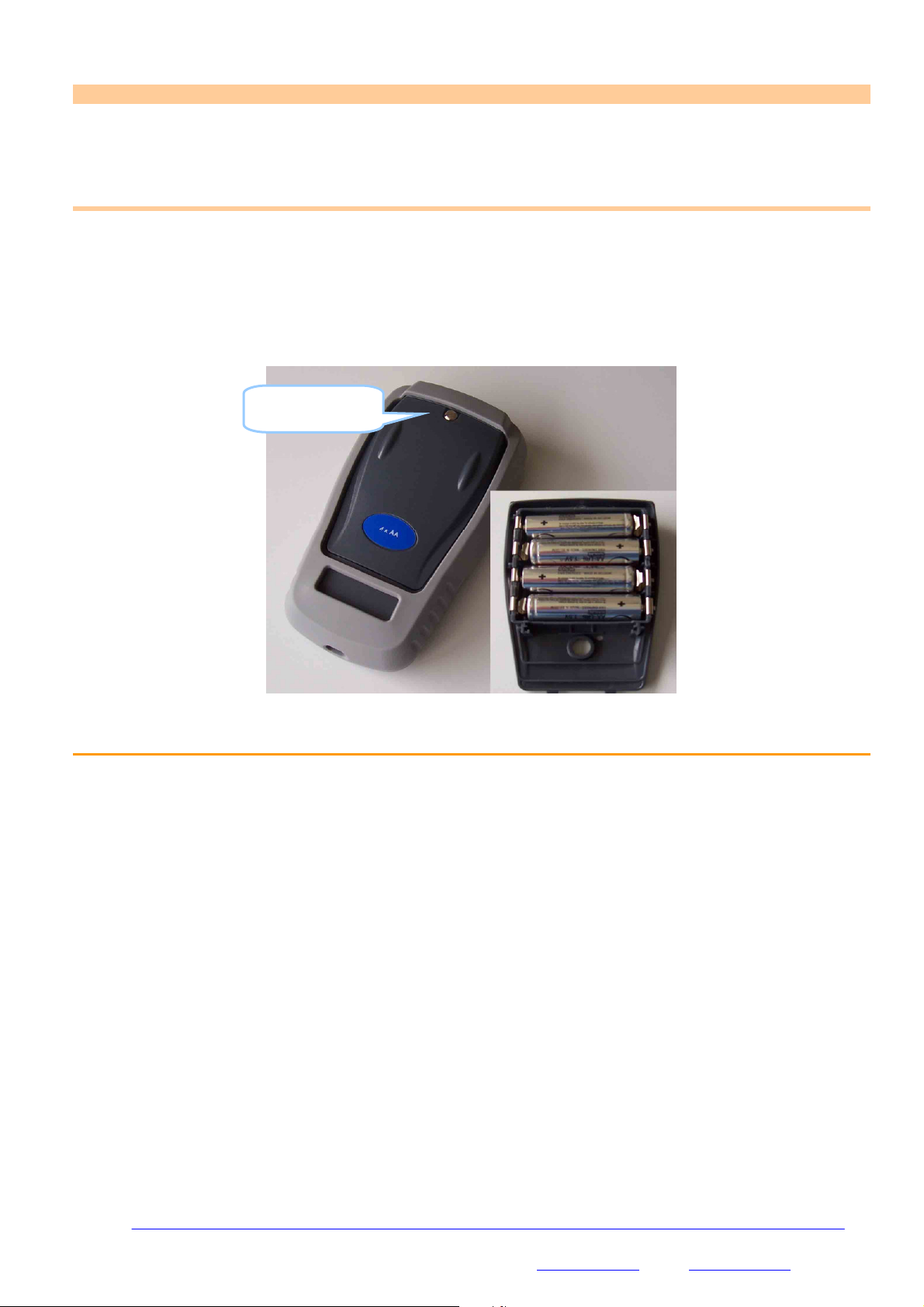
Power-up .....................................................................................................................................................
B.1.1
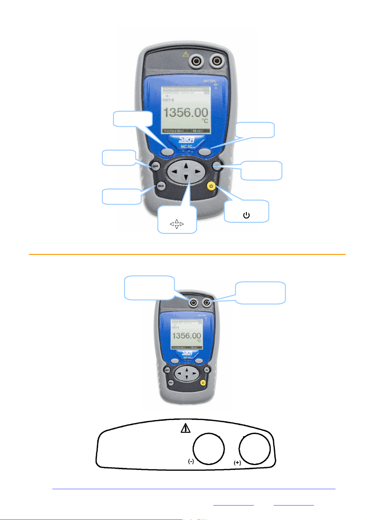
The keyboard.......................................................................................................................................
B.1.2
The measuring and simulation terminals................................................................................................ 10
B.1.3
The USB connector ............................................................................................................................. 11
B.1.4
The screen......................................................................................................................................... 11
B.1.5
Getting started (after power-up) .......................................................................................................... 12
B.1.6
Operating modes ................................................................................................................................ 13
C.
Mode Programming ..................................................................................................................................... 14
C.1.1
Voltage or temperature measurement by thermocouple........................................................................... 14
C.1.2
Voltage or temperature emission by thermocouple.................................................................................. 15
D.
Related Functions ....................................................................................................................................... 20
D.1
Scaling ...................................................................................................................................................... 20
D.2
Nulling....................................................................................................................................................... 21
D.3
Calibrated sensors ...................................................................................................................................... 22
D.4
Configuration of predefined set points ........................................................................................................... 24
D.5
Storage of acquisitions in progress................................................................................................................ 25
D.5.1
Synthesiser configuration .................................................................................................................... 2
D.5.2
Configuration of the ramp generation.................................................................................................... 31
E.
Parameter settings...................................................................................................................................... 34
E.1
Contrast adjustment.................................................................................................................................... 34
E.2
Date and time setting.................................................................................................................................. 34
E.3
“Preferences” setting. .................................................................................................................................. 35
E.3.1
Filtering setting. ................................................................................................................................. 35
E.3.2
Display resolution setting. ................................................................................................................... 35
E.3.3
Lighting duration setting...................................................................................................................... 35
E.3.4
“Key beeping” setting.......................................................................................................................... 35
E.3.5
Language setting ................................................................................................................................ 36
E.3.6
Temperature unit setting ..................................................................................................................... 36
E.4
“Maintenance” menu ................................................................................................................................... 36
E.5
“About the instrument” menu ....................................................................................................................... 36
F.
Technical specifications................................................................................................................................ 37
F.1
Measurement Function................................................................................................................................. 37
F.1.1
Constant voltage (measurement) ......................................................................................................... 37
F.1.2
Temperature per thermocouple (measurement)...................................................................................... 38
F.2
Emission function........................................................................................................................................ 3
F.2.1
Constant voltage simulating................................................................................................................. 3
F.2.2
Temperature per thermocouple (simulating) .......................................................................................... 3
F.3
Power supply - Autonomy................................................................................................................................. 40

SIKA, Dr. Siebert & Kühn GmbH & Co. KG, Struthweg 7- , 34260 Kaufungen, Germany 5/40
A. G
ENERAL
A.1 Introduction
The UC TC is a portable thermocouple temperature calibrator (compliant with EC standards). It is especially
designed for calibration and maintenance. It makes it possible to measure and to emit electrical measurements and
to simulate temperatures both on site as well as in a laboratory. It performs voltage and temperature measuring and
emission functions (continuous or LF ramps).
The UC TC features a large number of related functions which extend its range of application, including:
•Generation of default values, increases, single or cyclic ramps.
•Storage of acquisitions and display in the form of tables or trend curves.
•Use of calibrated sensors with their coefficients of correction
A range of improvements facilitates its operation:
•Rapid access to all functions.
•Intuitive user interface.
•160x160 graphic display
•Connection via 4 mm safety plugs or a miniature flat plug.
•Power supply via 4 AA batteries or rechargeable batteries with internal charger (Option).
The device is fitted in an elastomer-sheathed ABS case.
A.2 Parts
General characteristics:
•Portable device powered by 4 AA batteries (pack of Ni-MH storage batteries, 1.7 Ah optional).
•Hand strap for carrying and use on-site
•Graphic liquid crystal display: 160 x 160 pixels.
•Choice of language used for messages and programming of functions, gauges and parameters via 6-key
keyboard + 1 navigator.
•Backlit display accessible via a keyboard key, with the possibility of automatic black-out after a specific
programmable period of inactivity.
•Appearance: ABS case (elastomer-sheathed).
•Dimensions : 157 mm x 85 mm x 45 mm (without coating).
•Weight: 306 g without coating.
•IP54 tightness in compliance with standard EN 60529
A.3 Safety
A.3.1 Compliance with safety standards
The device complies with the applicable standards in force on the subject of electrical safety (EN 61010) as well as
on the electromagnetic compatibility of the electrical measuring instruments (EMC: EN61326).
These instructions for use contain information and warnings which must be observed by the user to protect the
latter against the dangers of electricity, to ensure the safe operation of the device and to protect it against any
mishandling which could damage or compromise the safety of use of the device.

SIKA, Dr. Siebert & Kühn GmbH & Co. KG, Struthweg 7- , 34260 Kaufungen, Germany 6/40
A.3.2 Environmental conditions
In accordance with publication CEI 359: operating category I.
Range of application of standards from 0 to 2200 m.
Reference temperature range: 23°C ± 5°C, relative humidity: 45 % to 75 %.
Nominal operating range: -10°C to +50°C, relative humidity: 20 % to 80 % non-condensing.
Operating range limit: -15°C to +55°C, relative humidity: 10 % to 80 % (70 % at 55°C).
Storage and transport temperature range limit: - 30°C to + 60°C (without the batteries).
A.3.3 Worn devices
Worn electrical devices can pollute the environment. We recommend you refrain from disposing of this device in
an ordinary waste bin, but rather that you use the recycling circuits available locally. If not, you can return the
device to us, and we will take care of its disposal free of charge.
A.3.3.1 Waste generated by the device
List of waste classified according to the decree published in the Official French Gazette dated 20
th
April 2002.
Decree no. 2002-540.
•16.02.14: Waste originating from electronic equipment:
Printed circuit boards making up the device.
•16.06.02: Batteries and storage battery (dangerous)
Alkaline Batteries (or NI-MH batteries).
•15.01.02: Packaging
ABS plastic device casing.
Elastomer conduit.
A.3.4 Device destruction procedure
Opening the device: unscrew the screw on the battery compartment, followed by the 5 screws securing the 2 shells.
Separate the 2 shells. Separate the PCB from the upper shell.
With regard to the batteries, you will find them in the battery compartment (see commissioning chapter).
In the case of the pack of batteries, there are 2 contaminants: NI-MH (Nickel-Metal Hybride) batteries and a PCB.
Separate these 2 items.
A.3.5 Instructions
The device was designed to operate safely if the instructions provided in the accompanying documents are
followed. Any other use may jeopardise the safety of the operator. Any use other than those specified in the
instructions is therefore dangerous and forbidden.

SIKA, Dr. Siebert & Kühn GmbH & Co. KG, Struthweg 7- , 34260 Kaufungen, Germany 7/40
A.3.6 Making measurements
The measuring leads and wires must be in good condition and must be replaced if their insulation appears faulty
(insulating material cut, burned, etc...).
Never exceed the protection value limits indicated in the specifications.
Before changing function, disconnect the measuring wires from the external circuit. When voltage measurements
are being made, even weak ones, keep in mind that the circuits may feature a dangerous voltage for the operator
compared to the ground.
Do not make any measurements when the device is linked up to another device using the USB link or when the
batteries are being charged.
A.3.7 Defects and abnormal stresses
Every time you believe the protection may have been compromised, switch off the device and prevent it from being
switched back on unexpectedly.
The protection may be impaired in the following cases, for example:
The device is visibly worn.
The device is no longer able to make precise measurements.
The device was stored in unfavourable conditions.
The device has undergone severe stresses during transport.
A.3.8 Definitions
A.3.8.1 Definition of the category and degree of pollution
CAT II 60V:
This notion of categories determines the maximum voltage which can be applied to the measuring inputs (it is also
referred to as the overvoltage category). For the UC TC, the ceiling overvoltage is (DC or AC)
POL 2:
The notion of pollution determines the clearance between circuits. Degree 2 authorises temporary conductivity
caused by condensation.
A.3.8.2 Table of symbols used
Symbol Name
Attention: see the accompanying documents
Earth
Compliant with the European Union directives
60V
CAT II Pol 2
Category II, Pollution 2.
Maximum common mode voltage compared with the
ground=60V

SIKA, Dr. Siebert & Kühn GmbH & Co. KG, Struthweg 7- , 34260 Kaufungen, Germany 8/40
A.4 Maintenance
The device must always be repositioned in accordance with the instructions provided herein. Any incomplete or
incorrect assembly could compromise the safety of the operator.
The authority responsible must regularly ensure that all safety-related items are not worn and ensure all the
preventive maintenance operations required are performed.
Before opening the device for any maintenance operations, you must make sure that all the wires are disconnected
from the appliance.
All adjustments, maintenance and repair work on the open device must be avoided as much as possible and, when
these are indispensable, they must be performed by qualified staff, who are well aware of the risks involved.

SIKA, Dr. Siebert & Kühn GmbH & Co. KG, Struthweg 7- , 34260 Kaufungen, Germany /40
B. U
SING THE INSTRUMENT
In order to use the device in all the safety required, all operators must read the paragraph on safety carefully, along
with the paragraph below.
B.1 Power-up
The device is delivered with 4 AA batteries of 1.5V each. It is wise to place these batteries in the compartment
provided for this purpose. To open up the compartment, unscrew the screw on the back of the box. Once the
batteries are in place, screw the cover back on.
Observe the polarity: an incorrect battery positioning could damage the device. The correct polarity is indicated
inside the compartment.
The figure below illustrates how to open the battery compartment as well as the correct positioning of each battery.
B.1.1 The keyboard
The keyboard features:
•2 function keys (F1 and F2) for the selection of the various menus displayed on the screen.
•The navigator, consisting of 4 arrows (up (↑
↑↑
↑), down (↓
↓↓
↓), right (
), left (
)
•A clear key (CLEAR).
•A device on/off and backlighting on/off key (ON/OFF).
Press briefly to start the device. During operation, press briefly to turn the lighting on or off. Press it longer
for 2 seconds to stop the device.
•A validation key (VAL).
•A HOLD key allows you to suspend a process temporarily (when pressed briefly). If you press it longer,
this key makes it possible to switch from measuring mode to emission mode and vice-versa.
Battery
compartment screw

SIKA, Dr. Siebert & Kühn GmbH & Co. KG, Struthweg 7- , 34260 Kaufungen, Germany 10/40
B.1.2 The measuring and simulation terminals
The UC TC is fitted with 2 safety bushes (4 mm in diameter) and a miniature flat plug for thermocouples. This
wiring is used both in measurement and emission mode (non-simultaneous).
HOLD
key
F1 function
key
CLEAR
key
Navigation
key
ON/OFF key
Confirmation
key (VAL)
F2 function
key
Positive terminal
in measurement
and emission
Negative
terminal in
measurement
and emission

SIKA, Dr. Siebert & Kühn GmbH & Co. KG, Struthweg 7- , 34260 Kaufungen, Germany 11/40
B.1.3 The USB connector
The UC TC is fitted with a USB connector (mini B) intended for uploading new software versions and device
adjustment.
B.1.4 The screen
The UC TC is fitted with a graphic LCD display with back-lighting. The display resolution is 160 x 160 pixels.
In normal operating conditions, the display is divided up into seven horizontal fields:
•The 1
st
field indicates the operating mode (Measurement or emission).
•The 2
nd
field indicates the date, time and battery charge.
•The 3
rd
field is reserved for icons indicating the operating mode (related functions: Scaling, filtering…etc).
•The 4
th
field indicates the operating mode, the gauge and certain related functions.
•The 5
th
field indicates the value of the measurement or of the emission. These values are expressed in mV,
°C, °F or as a %.
•The 6
th
field indicates (in measurement mode) the min., average and max. values of the measurement.
•Lastly, the 7
th
field indicates the functionality of keys F1 and F2.
USB port (mini B
connector)
Positive terminal
in measurement
and emission
Negative
terminal in
measurement
and emission

SIKA, Dr. Siebert & Kühn GmbH & Co. KG, Struthweg 7- , 34260 Kaufungen, Germany 12/40
The table below provides a definition of each pictogram displayed on the screen:
Symbol
Description
Emission mode in increases
Emission mode in single ramp
Emission mode in cyclic ramp
Scaling
On hold
Filtering
%PE function (Pleine Echelle: Full Scale)
Error (over-calibration in measurement or
error on the value emitted…)
Incremental mode using the arrows
Battery life indication
Acquisition in progress (the value on the right
of the pictogram indicates the number of
values recorded)
The table below provides a definition of each pictogram of the function keys
Symbol Description
Tab key
Open a drop-down list
Close a drop-down list
Delete the selected item
Clear the selection
Add the item being edited
B.1.5 Getting started (after power-up)
On power-up (inserting the batteries or pack of batteries), the device is automatically turned on (loading the
software in the memory). At this stage, we advise against connecting the device to an external circuit.
To avoid any signal conflicts, the device switches to measurement mode.
1
st
field
indicating the
operating mode
2
nd
field
indicating the
Date, time and
battery charge.
3
rd
field
indicating the
configuration by
pictograms
4
th
field indicating the
measurement or
simulation mode, the
gauge and the main
related functions.
5
th
field
indicating the
value of the
measurement
or the
emission value
(in mV, °C,°F
or %)
6
th
field
indicating
the min, ave
and max.
measureme
nt values.
7
th
field indicating
the functions of the
F1 and F2 keys.

SIKA, Dr. Siebert & Kühn GmbH & Co. KG, Struthweg 7- , 34260 Kaufungen, Germany 13/40
B.1.6 Operating modes
There are 2 different operating modes:
•Thermocouple measurement (displayed in mV or °C or °F),
•Simulation of thermocouple/voltage emission (value displayed in mV or °C or °F).
The functional and electrical characteristics not to be exceeded are described below:
B.1.6.1 Constant voltage measurement
Range +100mV
Resolution (display) 1 µV or 0.01 °C or 0.01 °F
Scope of range -10 mV to + 100 mV
Scaling yes
B.1.6.2 Voltage emission
Range + 80 mV
Resolution (display) 1 µV or 0.01 °C or 0.01 °F
Scope of range -9.5 mV to +80 mV
Scaling yes
B.1.6.3 Electrical characteristics not to be exceeded.
Function Range max V
in
Z
load
U
measurement
100 mV 60 V
U
emission
80 mV 1000 Ω
ΩΩ
Ωmin

SIKA, Dr. Siebert & Kühn GmbH & Co. KG, Struthweg 7- , 34260 Kaufungen, Germany 14/40
C. M
ODE
P
ROGRAMMING
C.1.1 Voltage or temperature measurement by thermocouple
•The choice of measurement or emission mode is made using the F2 key (mode menu).
•Using the navigation keys (↑
↑↑
↑and ↓
↓↓
↓), position the cursor in the Measurement field going down the menu.
•Confirm your choice using the VAL key.
Note that the Measurement mode is the mode selected by default.
•The function type selection (Thermocouple type) is made using the F1 key (Configuration menu).
•Using the navigation keys (↑
↑↑
↑and ↓
↓↓
↓), position the cursor in the Function field.
•Confirm the latter using the VAL key.
In the CONFIGURATION MESURE (MEASUREMENT CONFIGURATION) menu, position the cursor
in the thermo couple field using the F1 key.
•Enter the thermo couple menu using the F2 key.
•Choose the type of thermocouple (K,T, J…), using the navigation keys (↑
↑↑
↑and ↓
↓↓
↓).
•Press VAL to confirm.
•Using the F1 key, define the Unit by positioning the cursor on it.
•Enter the menu by pressing F2.
•Using the navigation keys (↑
↑↑
↑and ↓
↓↓
↓), choose the unit.
•Press VAL to confirm.

SIKA, Dr. Siebert & Kühn GmbH & Co. KG, Struthweg 7- , 34260 Kaufungen, Germany 15/40
NOTE:
Attention, the choice of °C or °F is made in the Setup\Preferences\temp unit menu
•Using the F1 key, define the CSF used by positioning the cursor on it.
•Enter the menu by pressing F2.
•Using the navigation keys (↑
↑↑
↑and ↓
↓↓
↓), choose the CSF (OFF: None, ON: internal or programmed).
•Press VAL to confirm.
•Press VAL (again) to confirm the desired function and go back to the measurement screen.
The Measurement mode makes it possible to display the Min (bottom left), Average (bottom centre) and Max
values (bottom right) from the last RAZ Min/Max command.
•Access this command by pressing the F2 key.
•Using the navigation keys (↑
↑↑
↑and ↓
↓↓
↓), position the cursor in the RAZ Min/Max field.
•Confirm the latter using the VAL key.
Note:
Following a significant thermal shock, it is advisable to allow the device to stabilise its temperature to use the
internal reference junction (CSF) with the utmost precision.
C.1.2 Voltage or temperature emission by thermocouple
To access the Emission mode:
•The choice of Emission mode is made using the F2 key (mode menu).
•Using the navigation keys (↑
↑↑
↑and ↓
↓↓
↓), position the cursor in the Emission field going down the menu.
•Confirm your choice using the VAL key.

SIKA, Dr. Siebert & Kühn GmbH & Co. KG, Struthweg 7- , 34260 Kaufungen, Germany 16/40
Once you have confirmed the Emission mode, define the type of generation:
•Continuous (manual or arrows or default editing).
•Incremental (by step or “manual default”).
•By single ramp (only one ramp emitted).
•By cyclic ramp.
•Synthesiser ("automatic default”).
Voltage or temperature generation/manual editing?
•Press the F2 key to display the edit menu.
•Using the navigation keys (↑
↑↑
↑and ↓
↓↓
↓), choose the Manual edit mode and confirm (VAL key).
•Press VAL again and enter your value using the navigation keys:
o↑
↑↑
↑and ↓
↓↓
↓to increase or decrease the value
o
and
to select the digit to modify (hundreds/tens/unit/decimal place/hundreds).
Note:
If the Scaling mode is ON, the value to edit is expressed as a %, otherwise this value is expressed in Volts or in °C
or °F.
Voltage or temperature generation/arrow editing?
•Press the F2 key to display the edit menu.
•Using the navigation keys (↑
↑↑
↑and ↓
↓↓
↓), choose the Arrows edit mode and confirm (VAL key).
•Use the navigation keys to enter the value:
o↑
↑↑
↑and ↓
↓↓
↓to increase or decrease the value
o
and
to select the digit to modify (hundreds/tens/unit/decimal place/hundreds).

SIKA, Dr. Siebert & Kühn GmbH & Co. KG, Struthweg 7- , 34260 Kaufungen, Germany 17/40
Voltage or temperature generation/incremental editing?
•Press the F2 key to display the edit menu.
•Using the navigation keys (↑
↑↑
↑and ↓
↓↓
↓), choose the INCREASES mode and confirm (VAL key).
The values emitted are those defined in the CONFIGURATION/RAMP menu (see the chapter entitled Related
functions).
•Using the navigation key (↑
↑↑
↑), start the automatic increases phase (following the parameters programmed in
the CONFIGURATION/RAMP menu).
•Using the navigation key (↓
↓↓
↓), you can decrease automatically starting from the max. programmed voltage
(or temperature).
•Using the navigation key (
), you can increase manually the voltage (or temperature) emitted (following
the parameters programmed in the CONFIGURATION/RAMP menu).
•Using the navigation key (
), you can decrease manually the voltage (or temperature) emitted starting
from the max. programmed voltage.
Voltage or temperature generation/single ramp editing?
•Press the F2 key to display the edit menu.
•Using the navigation keys (↑
↑↑
↑and ↓
↓↓
↓), choose the SINGLE RAMP mode and confirm (VAL key).
The values emitted are those programmed in the CONFIGURATION/RAMP menu (see the chapter entitled Related
functions).
•Using the navigation key (↑
↑↑
↑), start the automatic increases phase (following the parameters programmed in
the CONFIGURATION/RAMP menu).
•Using the navigation key (↓
↓↓
↓), you can decrease automatically starting from the max. programmed voltage
(or temperature).
•Using the navigation key (
), you can increase manually the voltage (or temperature) emitted (following
the parameters programmed in the CONFIGURATION/RAMP menu).
•Using the navigation key (
), you can decrease manually the voltage emitted starting from the max.
programmed voltage (or temperature).
The Hold key allows you to stop generating or to resume it
You can resume the generation of the ramp in step-by-step mode by pressing the navigation keys (
and
) or in
automatic generation using the navigation keys (↑
↑↑
↑and ↓
↓↓
↓).
You can delay the emission by a programmable amount of time (in the CONFIGURATION/RAMP/DELAY
menu)
Indicates that
the mode used is
the arrows mode
Digit selected
during editing

SIKA, Dr. Siebert & Kühn GmbH & Co. KG, Struthweg 7- , 34260 Kaufungen, Germany 18/40
Voltage or temperature generation/cyclic ramp editing?
•Press the F2 key to display the edit menu.
•Using the navigation keys (↑
↑↑
↑and ↓
↓↓
↓), choose the CYCLIC RAMP mode and confirm (VAL key).
The values emitted are those programmed in the CONFIGURATION/RAMP menu (see the chapter entitled Related
functions).
•Using the navigation key (↑
↑↑
↑), start the automatic increases phase (following the parameters programmed in
the CONFIGURATION/RAMP menu).
•Using the navigation key (↓
↓↓
↓), you can decrease automatically starting from the max. programmed voltage
(or temperature).
•Using the navigation key (
), you can increase manually the voltage (or temperature) emitted (following
the parameters programmed in the CONFIGURATION/RAMP menu).
•Using the navigation key (
), you can decrease manually the voltage emitted starting from the max.
programmed voltage (or temperature).
The Hold key allows you to stop generating or to resume it
You can resume the generation of the ramp in step-by-step mode by pressing the navigation keys (
and
) or in
automatic generation using the navigation keys (
and
).
Voltage or temperature generation/default editing?
The default emission mode is a mode that makes it possible to generate manually the values stored for the
synthesiser function.
•Press the F2 key to display the edit menu.
•Using the navigation keys (↑
↑↑
↑and ↓
↓↓
↓), choose the Default values mode and confirm (VAL key).
•Using the navigation keys (↑
↑↑
↑and ↓
↓↓
↓), select the value that needs to be emitted.
•Confirm using the VAL key.
Values to be
emitted

SIKA, Dr. Siebert & Kühn GmbH & Co. KG, Struthweg 7- , 34260 Kaufungen, Germany 1 /40
Voltage or temperature generation/Synthesiser?
•Press the F2 key to display the edit menu.
•Using the navigation keys (↑
↑↑
↑and ↓
↓↓
↓), choose the Synthesiser mode and confirm (VAL key).
The values emitted are those programmed in the CONFIGURATION/Synthesiser menu (see the chapter entitled
Related functions).
•Using the navigation key (↑
↑↑
↑), start the automatic increases phase (following the parameters programmed in
the CONFIGURATION/Synthesiser menu).
•Using the navigation key (↓
↓↓
↓), you can decrease automatically starting from the max. programmed voltage
(or temperature).
•Using the navigation key (
), you can increase manually the voltage (or temperature) emitted (following
the parameters programmed in the CONFIGURATION/Synthesiser menu).
•Using the navigation key (
), you can decrease manually the voltage emitted starting from the max.
programmed voltage (or temperature).
The Hold key allows you to stop generating or to resume it
You can resume the generation of the ramp in step-by-step mode by pressing the navigation keys (
and
) or in
automatic generation using the navigation keys (
and
).
The configuration of the parameters for the ramps and default values is explained in the chapter entitled “Related
Functions”.
Notes:
Following a significant thermal shock, it is advisable to allow the device to stabilise its temperature to use the
internal reference junction (CSF) with the utmost precision.

SIKA, Dr. Siebert & Kühn GmbH & Co. KG, Struthweg 7- , 34260 Kaufungen, Germany 20/40
D. R
ELATED
F
UNCTIONS
D.1 Scaling
The scale correction function performs conversion operations between the electrical values measured and the
physical values converted.
This linearisation operation makes it possible to correct partially the errors induced by non-linear sensor/converter
systems.
The Scaling function makes it possible to define up to 10 right-segments, i.e. 11 points, in order to approach as
much as possible the non-linear response curve, and to make the scale corrections according to each segment.
The pictogram is displayed on the screen in the active window when the scaling function is enabled.
The Define/list of points menu makes it possible to program up to
10 lines of 2 values
X and Y= f(X).
In measurement mode: X = Value measured
Y = Value displayed
In emission mode: X = Value displayed
Y = Value emitted.
The lines entered are sorted according to the X in increasing order, to scale an X-value, the device seeks the 2 lines
n and m=n+1 which frame it, and extrapolates linearly:
Y = Yn + (X-Xn) x (Ym-Yn)/(Xm-Xn)
Use the function keys to edit the points:
To add a line: enter X and Y, then enable the function key.
To select a line in a list, use the Up and Down navigation keys.
To delete a selected line, use the key.
To move from one field to the next, use the key.
Table of contents
Other SIKA Test Equipment manuals
Popular Test Equipment manuals by other brands

Respirex
Respirex AUTOMATIC TEST BOX manual

Dräger
Dräger Alcotest 6510 Instructions for use

Dräger
Dräger Alcotest 6820 instruction manual

Vernier
Vernier Go Direct GDX-VSMT quick start guide

Keysight Technologies
Keysight Technologies 85041A Operating and service manual

Rigol
Rigol DL3000 Series Programming guide