NI 9265E User manual

OPERATING INSTRUCTIONS AND SPECIFICATIONS
NI 9265E
4-Channel, 0–20 mA, 16-Bit Analog Current Output
Module

NI 9265E Operating Instructions and Specifications 2 ni.com
This document describes how to use the National Instruments 9265E
and includes dimensions, terminal assignments, and specifications for
the NI 9265E. Visit ni.com/info and enter rdsoftwareversion
to determine which software you need for the modules you are using.
For information about installing, configuring, and programming the
system, refer to the system documentation. Visit ni.com/info and
enter cseriesdoc for information about C Series documentation.
Caution National Instruments makes no electromagnetic
compatibility (EMC) or CE marking compliance claims
for the NI 9265E. The end-product supplier is responsible
for conformity to any and all compliance requirements.
Caution The NI 9265E must be installed inside a suitable
enclosure prior to use. Hazardous voltages may be present.

© National Instruments Corp. 3 NI 9265E Operating Instructions and Specifications
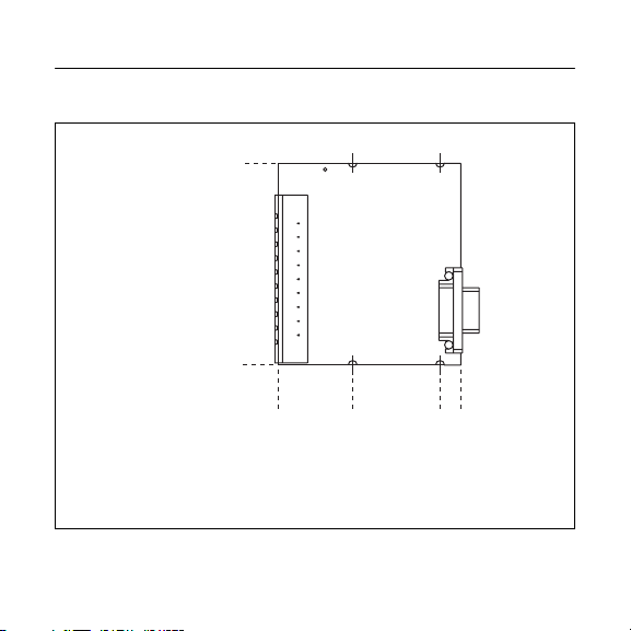
NI 9265E Dimensions
The following figure shows the dimensions of the NI 9265E.
Figure 1. NI 9265E Dimensions in Millimeters (Inches)
73.4 (2.89)
0.0 (0.00)
26.7 (1.05)
58.4 (2.30)
66.0 (2.60)
0.0 (0.00)

NI 9265E Operating Instructions and Specifications 4 ni.com
Connecting the NI 9265E
The NI 9265E has a 10-terminal, detachable screw-terminal
connector that provides connections for 4 analog output channels.
Figure 2. NI 9265E Terminal Assignments
0
1
2
3
4
5
6
7
8
9
AO0
COM0
AO1
COM1
AO2
COM2
AO3
COM3
Vsup
Power Supply COM

© National Instruments Corp. 5 NI 9265E Operating Instructions and Specifications
The NI 9265E has four analog output channels, AO. Each channel
has a common terminal, COM, that is internally connected to the
isolated ground reference of the module. The NI 9265E also has a
terminal for an external power supply, Vsup, and an external power
supply common terminal, Power Supply COM.
Each AO channel has a digital-to-analog converter (DAC) that
produces a current signal. Each channel also has overvoltage and
short-circuit protection. Refer to the Specifications section for
more information about the overvoltage and short-circuit
protection. Refer to Figure 3 for an illustration of the output
circuitry for one channel of the NI 9265E.
You can connect a load to each channel of the NI 9265E. Connect
the positive lead of the load to the AO terminal. Connect the ground
of the load to the corresponding COM terminal. Refer to Figure 3
for an illustration of how to connect a load to the NI 9265E.

NI 9265E Operating Instructions and Specifications 6 ni.com
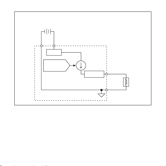
Figure 3. Connecting a Load to the NI 9265E
You must connect an external power supply to the NI 9265E. This
power supply provides the current for the devices you connect to
the module. Connect the positive lead of the power supply to the
supply terminal, Vsup, and the negative lead of the power supply to
Power Supply COM.
AO
COM
NI 9265E
Isolated DAC
External
Power Supply
+
_
Vsup
Power
Supply
COM
Load
Protection
DC/DC

© National Instruments Corp. 7 NI 9265E Operating Instructions and Specifications
Note You must use 2-wire ferrules to create a secure
connection when connecting more than one wire to a
single terminal on the NI 9265E.
When the module powers on, the channels output the startup
current. Refer to the Specifications section for more information
about startup current. Refer to the software help for information
about configuring startup output states in software. Visit
ni.com/info and enter cseriesdoc for information about
C Series documentation.
Sleep Mode
This module supports a low-power sleep mode. Support for sleep
mode at the system level depends on the chassis that the module is
plugged into. Refer to the chassis manual for information about
support for sleep mode. If the chassis supports sleep mode, refer to
the software help for information about enabling sleep mode. Visit
ni.com/info and enter cseriesdoc for information about
C Series documentation.

NI 9265E Operating Instructions and Specifications 8 ni.com
Typically, when a system is in sleep mode, you cannot
communicate with the modules. In sleep mode, the system
consumes minimal power and may dissipate less heat than it does
in normal mode. Refer to the Specifications section for more
information about power consumption and thermal dissipation.
Specifications
The following specifications are typical for the range –40 to 85 °C
internal to any enclosures unless otherwise noted. All voltages are
relative to COM unless otherwise noted.
Output Characteristics
Number of channels.......................... 4 analog output channels
DAC resolution ................................. 16 bits
Type of DAC ..................................... String
Power-on/Startup/
Power-down current.......................... 0.0 mA
Full-scale output current
Nominal ...................................... 20.0 mA
Minimum .................................... 20.1 mA

© National Instruments Corp. 9 NI 9265E Operating Instructions and Specifications
Typical ........................................ 20.6 mA
Maximum ................................... 21.0 mA
Output range ..................................... 0 to 20 mA
Compliance voltage .......................... 12 VDC max
Maximum load.................................. 600 Ω
Accuracy
Stability
Gain drift .................................... 30 ppm/°C
Offset drift .................................. 45 ppm/°C
Measurement Conditions
Percent of
Reading
(Gain Error)
Percent of
Range*
(Offset Error)
Calibrated, typ (25 °C, ±5 °C) 0.11% 0.19%
Calibrated, max (–40 to 85 °C) 0.25% 0.4%
Uncalibrated, typ (25 °C, ±5 °C) 0.35% 1.4%
Uncalibrated, max (–40 to 85 °C) 0.85% 2.5%
* Range equals 0 to 20.6 mA

NI 9265E Operating Instructions and Specifications 10 ni.com
External power supply
voltage range (Vsup) .......................... 9–36 VDC
Protection (AO, Vsup)
Overvoltage ................................ ±40 V
Short-circuit................................ Indefinitely
Update time
Noise................................................. 600 nArms
Crosstalk ........................................... –90 dB
Settling time (to 1 LSB)
Full-scale step............................. 10 μs
1 mA step ................................... 5 μs
Number of
Channels
Update Time for R Series
Expansion Chassis
Update Time for
Any Other Chassis
13.5 μs 3 μs
26.5 μs 5 μs
3 9 μs7.5 μs
412 μs9.5 μs

© National Instruments Corp. 11 NI 9265E Operating Instructions and Specifications
Glitch energy .................................... Unmeasurable
Monotonicity..................................... 16 bits
DNL .................................................. 1 LSB max
INL.................................................... ±16 LSB
MTBF ............................................... 1,014,487 hours at 25 °C;
Bellcore Issue 2, Method 1,
Case 3, Limited Part Stress
Method
Note Contact NI for Bellcore MTBF specifications
at other temperatures or for MIL-HDBK-217F
specifications.
Power Requirements
Power consumption from chassis
Active mode ............................... 230 mW max
Sleep mode ................................. 25 μW max
Thermal dissipation (at 85 °C)
Active mode ............................... 1.5 W max
Sleep mode ................................. 10 mW max

NI 9265E Operating Instructions and Specifications 12 ni.com
Power consumption from external power supply
Active mode ............................... 1.4 W max
Sleep mode ................................. 10 mW
Physical Characteristics
Use a dry, low-velocity stream of air to clean the module. If
needed, use a soft-bristle brush for cleaning around components.
Note For two-dimensional drawings and
three-dimensional models of the C Series module and
connectors, visit ni.com/dimensions and search by
module number.
Screw-terminal wiring ...................... 12 to 24 AWG copper
conductor wire with 10 mm
(0.39 in.) of insulation
stripped from the end
Ferrules ............................................. 0.25 mm2to 2.5 mm2
Torque for screw terminals ............... 0.5 to 0.6 N · m
(4.4 to 5.3 lb · in.)
Weight............................................... 67 g (2.4 oz)

© National Instruments Corp. 13 NI 9265E Operating Instructions and Specifications
Safety
Maximum Voltage1
Connect only voltages that are within the following limits.
Channel-to-COM or Vsup-to-COM ... ±40 V max
Isolation Voltages
Channel-to-channel........................... None
Channel-to-earth ground, Vsup-to-earth ground,
or COM-to-earth ground
Continuous ................................. 250 Vrms,
Measurement Category II,
(Double insulation)
Withstand.................................... 2,300 Vrms, verified by a 5 s
dielectric withstand test
1 The maximum voltage that can be applied between any channel or Vsup terminal
and a COM terminal without damaging the module or other devices.

NI 9265E Operating Instructions and Specifications 14 ni.com
Measurement Category II is for measurements performed on
circuits directly connected to the electrical distribution system.
This category refers to local-level electrical distribution, such as
that provided by a standard wall outlet, for example, 115 V for U.S.
or 230 V for Europe.
Caution Do not connect the NI 9265E to signals or use
for measurements within Measurement Categories III
or IV.
Safety Standards
This product meets the requirements of the following standards of
safety for electrical equipment for measurement, control, and
laboratory use when installed in a suitable enclosure:
• IEC 61010-1, EN 61010-1
• UL 61010-1, CSA 61010-1
Note For UL and other safety certifications, refer to the
product label or the Online Product Certification section.

© National Instruments Corp. 15 NI 9265E Operating Instructions and Specifications
Online Product Certification
Refer to the product Declaration of Conformity (DoC) for
additional regulatory compliance information. To obtain product
certifications and the DoC for this product, visit ni.com/
certification, search by module number or product line, and
click the appropriate link in the Certification column.
Environmental
National Instruments C Series modules are intended for indoor use
only but may be used outdoors if installed in a suitable enclosure.
Refer to the manual for the chassis you are using for more
information about meeting these specifications.
Operating temperature
(IEC 60068-2-1, IEC 60068-2-2) ..... –40 to 85 °C
Storage temperature
(IEC 60068-2-1, IEC 60068-2-2) ..... –40 to 85 °C
Operating humidity
(IEC 60068-2-56).............................. 10 to 90% RH,
noncondensing
Storage humidity
(IEC 60068-2-56).............................. 5 to 95% RH,
noncondensing

NI 9265E Operating Instructions and Specifications 16 ni.com
Maximum altitude............................. 2,000 m
Pollution Degree (IEC 60664) .......... 2
Environmental Management
National Instruments is committed to designing and manufacturing
products in an environmentally responsible manner. NI recognizes
that eliminating certain hazardous substances from our products is
beneficial to the environment and to NI customers.
For additional environmental information, refer to the NI and the
Environment Web page at ni.com/environment. This page
contains the environmental regulations and directives with which
NI complies, as well as other environmental information not
included in this document.
Waste Electrical and Electronic Equipment (WEEE)
EU Customers At the end of the life cycle, all products
must be sent to a WEEE recycling center. For more
information about WEEE recycling centers and National
Instruments WEEE initiatives, visit ni.com/
environment/weee.

© National Instruments Corp. 17 NI 9265E Operating Instructions and Specifications
Calibration
You can obtain the calibration certificate and information about
calibration services for the NI 9265E at ni.com/calibration.
Calibration interval ........................... 1 year
⬉ᄤֵᙃѻક∵ᶧࠊㅵ⧚ࡲ⊩ ˄Ё
RoHS
˅
Ёᅶ᠋
National Instruments ヺড়Ё⬉ᄤֵᙃ
ѻકЁ䰤ࠊՓ⫼ᶤѯ᳝ᆇ⠽䋼ᣛҸ (RoHS)DŽ݇Ѣ
National Instruments Ё RoHS ড়㾘ᗻֵᙃˈ䇋ⱏᔩ
ni.com/environment/rohs_chinaDŽ(For information
about China RoHS compliance, go to ni.com/
environment/rohs_china.)

NI 9265E Operating Instructions and Specifications 18 ni.com
Where to Go for Support
The National Instruments Web site is your complete resource for
technical support. At ni.com/support you have access to
everything from troubleshooting and application development
self-help resources to email and phone assistance from
NI Application Engineers.
National Instruments corporate headquarters is located at
11500 North Mopac Expressway, Austin, Texas, 78759-3504.
National Instruments also has offices located around the world to
help address your support needs. For telephone support in the
United States, create your service request at ni.com/support
and follow the calling instructions or dial 512 795 8248. For
telephone support outside the United States, contact your local
branch office:
Australia 1800 300 800, Austria 43 662 457990-0,
Belgium 32 (0) 2 757 0020, Brazil 55 11 3262 3599,
Canada 800 433 3488, China 86 21 5050 9800,
Czech Republic 420 224 235 774, Denmark 45 45 76 26 00,
Finland 358 (0) 9 725 72511, France 01 57 66 24 24,
Germany 49 89 7413130, India 91 80 41190000,
Israel 972 3 6393737, Italy 39 02 41309277, Japan 0120-527196,

© 2009 National Instruments Corp. All rights reserved.
372727A-01 Jan09
National Instruments, NI, ni.com, and LabVIEW are trademarks of National Instruments Corporation. Refer to the
Terms of Use section on ni.com/legal for more information about National Instruments trademarks. Other
product and company names mentioned herein are trademarks or trade names of their respective companies.
For patents covering National Instruments products/technology, refer to the appropriate location: Help»Patents
in your software, the patents.txt file on your media, or the National Instruments Patent Notice
at ni.com/patents.
Korea 82 02 3451 3400, Lebanon 961 (0) 1 33 28 28,
Malaysia 1800 887710, Mexico 01 800 010 0793,
Netherlands 31 (0) 348 433 466, New Zealand 0800 553 322,
Norway 47 (0) 66 90 76 60, Poland 48 22 328 90 10,
Portugal 351 210 311 210, Russia 7 495 783 6851,
Singapore 1800 226 5886, Slovenia 386 3 425 42 00,
South Africa 27 0 11 805 8197, Spain 34 91 640 0085,
Sweden 46 (0) 8 587 895 00, Switzerland 41 56 2005151,
Taiwan 886 02 2377 2222, Thailand 662 278 6777,
Turkey 90 212 279 3031, United Kingdom 44 (0) 1635 523545
Table of contents
Other NI Control Unit manuals
Popular Control Unit manuals by other brands

Agilent Technologies
Agilent Technologies G1157A user manual

BS&B
BS&B NACIONAL 3-5111 Instruction and maintenance manual

Spartan
Spartan 4D85 Series Application and installation guide

Supermicro
Supermicro MicroBlade MBI-6218G-T81X user manual

Proxxon
Proxxon CU 4 manual

Paradyne
Paradyne iMarc SLV9128 installation instructions