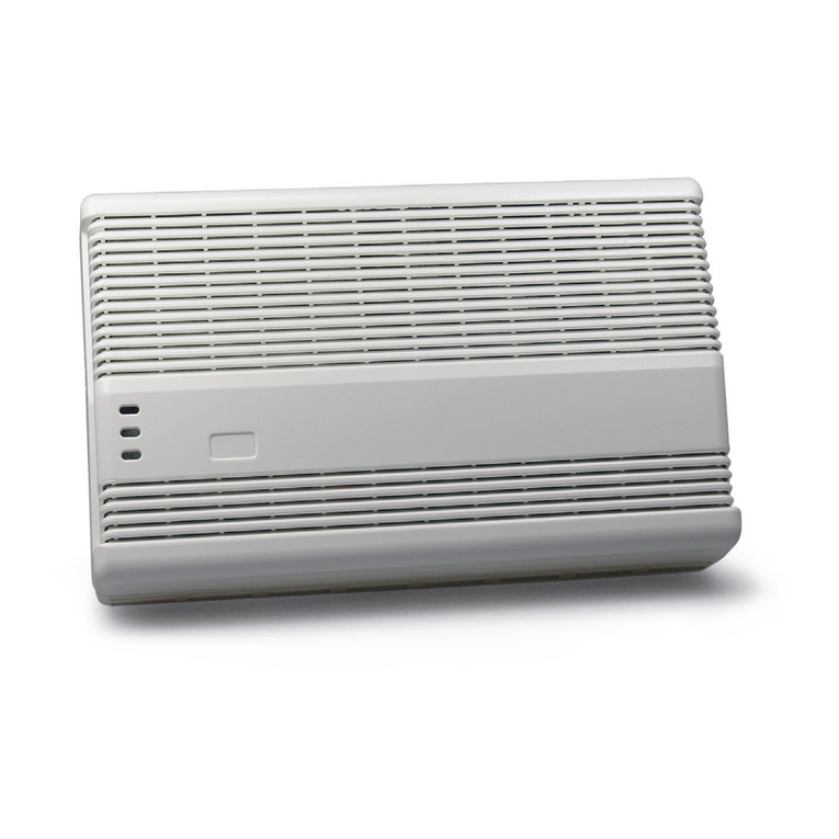
SILENTRON 4024 User manual

4024-xA110606GM
Dichiarazione di conformità CE : l'apparecchiatura qui descritta funziona a 5V in corrente continua ed è componente accessorio di un sistema di allarme elettronico che fa capo alla centrale
4000 Sil-Bus, quindi non utilizzabile svincolata da tale apparecchio, pur essendo conforme alle seguenti norme:
1) Direttiva CE 2004/108 del 15 dicembre 2004, relative alla compatibilità elettromagnetica. Le Norme e/o specifiche tecniche applicate sono le seguenti: EN 50130-4 (1995-12) + A1 (1998-04)
+ A2 (2003-01) - EN 55024 (1998-09) +A1 (2001-10) + A2 (2003-01) - EN 301489-1 V1.8.1 (2008-04) - EN 301489-3 V. 1.4.1 (2002-08) - EN 301489-7 V1.3.1 (2005-11).
2) Direttiva CE 2006/95 del 12/12/2006: è applicata la Norma EN 60950-1 (2006-049).
Avvertenze: l'apparecchiatura qui descritta deve essere installata e messa in opera da tecnici specializzati, nel rispetto delle Norme vigenti.
Funzionamento: l'apparecchio consente di inserire totalmente (ON) o parzialmente (ON/P) e disinserire (OFF) un sistema di allarme Sil-Bus attraverso un TAG elettromagnetico codificato in
oltre un milione di combinazioni diverse. Le manovre avvengono automaticamente in sequenza: avvicinare il TAG al marchio di fabbrica sul contenitore dell'apparecchio e mantenerlo in
posizione fino a manovra effettuata.
ON - inserimento totale: avvicinare il TAG e toglierlo non appena il led rosso si accende.
ON/P –inserimento parziale : avvicinare il TAG e tenerlo in posizione fino a quando il led rosso lampeggia.
OFF –disinserimento : con centrale inserita, avvicinare il TAG e tenerlo in posizione fino ad accensione del led verde.
Led giallo: se lampeggia all’inserimento (ON – ON/P) indica che vi sono infissi protetti aperti nel sistema e/o allarmi in corso. Se lampeggia successivamente al disinserimento significa che è
avvenuto un allarme nel periodo di inserimento: vedere memoria eventi.
JP 1 - Visualizzazioni: in funzione della programmazione i led rosso, verde e giallo possono restare accesi ( JP1 aperto) o spegnersi dopo 30 secondi (JP1 chiuso). Il ponticello JP1 deve
essere predisposto opportunamente prima del collegamento elettrico dell’apparecchio.
Attenzione ! Blocco dell’inserimento con infissi aperti: se la centrale è programmata in questo modo (EN 50131) in caso di tentativi di inserimento totale o parziale con infissi aperti
lampeggiano tutti i led (continuamente o per 30 secondi in funzione della programmazione di jP1) e la centrale non si inserisce.
Istruzioni per l'installazione:
a) Fissare l'apparecchio al muro in posizione adatta all'impiego tramite viti e tasselli in dotazione (vedere disegni)
b) Ricavare il vano per il passaggio dei cavi sfondando l'apposita parete predisposta sul fondo del contenitore
c) Collegare un cavo a 4 conduttori isolati diametro minimo 0,22mm e di lunghezza massima 20m fra l'apparecchio ed il Touch-screen Sil-Bus cod. 4020 oppure 4021, non alimentato. Evitare
che parte non isolata dei conduttori fuoriesca dai morsetti per evitare corti circuiti.
Attenzione: qualora il cavo di collegamento sia lungo e transiti in parallelo a cavi 230V potrebbero verificarsi malfunzionamenti dovuti a disturbi. Nel caso ridurre la lunghezza e trovare percorsi
alternativi.
d) Abilitare la protezione antiapertura (tamper) sfilando il ponticello relativo ed infilandolo su un solo terminale (contatto aperto)
e) Richiudere il contenitore con l'apposito anello elastico, alimentare il Touch screen e procedere con la programmazione dei TAG e le prove.
Istruzioni di programmazione, messa in opera ed utilizzo: vedere manuale della centrale cod. 4000 Sil-Bus
Caratteristiche tecniche:
classe ambientale 3 - esterno protetto alimentazione: 5V CC (Touch-screen) assorbimento: 15mA
Antimanomissione: l’apparecchio può essere installato anche in zone non protette dai rivelatori in quanto la sua manomissione (apertura del contenitore) genera allarme e comunque non
consente il disinserimento né il blocco del bus nemmeno con interventi sui conduttori di collegamento.

2
4024 External TAG reader (connected to keypad Sil-Bus)
EC Declaration of conformity: the equipment here described operates at 12V DC and is an accessory component of an electronic alarm system connected with the 4000 Sil-Bus control unit.
Therefore it cannot be used if it is not connected to this appliance, although it complies with the standards below:
1) EC Directive 2004/108 of 15th December 2004, relating to electromagnetic compatibility. The Standards and/or technical specifications applied are: EN 50130-4 (1995-12) + A1 (1998-04) +
A2 (2003-01) - EN 55024 (1998-09) +A1 (2001-10) + A2 (2003-01) - EN 301489-1 V1.8.1 (2008-04) - EN 301489-3 V. 1.4.1 (2002-08) - EN 301489-7 V1.3.1 (2005-11)
2) EC Directive 2006/95 del 12/12/2006: the EN 60950-1 (2006-049) Standard is applied.
Notice: the equipment here described must be installed and started up by specialised technicians in accordance with current Regulations.
Functioning: the appliance allows to totally arm (ON), partially arm (P/ON) and disarm (OFF) a Sil-Bus alarm system using an electromagnetic TAG encoded in more than one million different
combinations. The operations are carried out automatically in sequence: approach the TAG close to the trademark on the appliance box and hold it in this position until the operation is
completed.
ON –total arming: approach the TAG and remove it immediately once the red LED is ON.
P/ON –partial arming : approach the TAG and hold it in the same position until the red LED blinks.
OFF –disarming : with control panel armed, approach the TAG and hold it in the same position until the green LED is ON.
Yellow Led: if it blinks during an arming (ON –P/ON) it means there are protected frames open in the system and/or actives alarms. If it blinks after disarming it means that an alarm is
occurred during the arming period: check the events memory.
JP 1 –Visual Indications: depending by the setting the LEDs red, green and yellow can remain always ON ( JP1 open) or be deactivated after 30 seconds (JP1 closed). The jumper JP1 has
to be correctly set before of the electrical connection and power-on of the appliance
Warning ! Block of arming with open frames: if the control panel is programmed in this way (EN 50131), in case of total/partial arming attempts with open frames, all the leds are blinking
(continuously or for 30 seconds depending by the JP1 setting) and the control panel is not armed.
Installation instructions:
a) Install the appliance on the wall in a position adequate to its use using the supplied screws and inserts (see illustrations)
b) Create the space for the cables passage by breaking the designated plastic area on the bottom of the box
c) Connect a cable with 4 isolated conductors with a diameter of at least 0.22mm and maximum 20m long between the appliance and the Sil-Bus Touch-screen (code 4020 or 4021), not
powered. The non-insulated part of the conductors should completely be in the clamps to prevent short-circuits.
Attention: If the connection cable is long and pass together with 230V cables, malfunctions due to interference may occur. In this case reduce the length and find alternative passages.
d) Enable the anti-opening protection (tamper) by removing the relative jumper and inserting it in just one terminal (open contact)
e) Close the box using the designated elastic ring, power the Touch screen and proceed with the TAGs programming and tests.
Programming, start-up and user instructions: see manual of the control panel code 4000 Sil-Bus
Technical features:
environmental class 3 - protected external power supply: 5V CC (Touch-screen) absorption: 15mA
Anti-tampering: the appliance can be installed even in areas not protected by detectors, as tampering generates an alarm and in any case does not allow disarming the system or blockage of
the bus, not even with intervention on the connection wires.

3
4024 Lecteur TAG externe (connection au clavier Sil Bus)
Déclaration de conformité CE : L’appareil qui est décrit fonctionne à 5V en courant continu et est un composant accessoire d’un système d’alarme électronique qui est géré par la centrale
4000 Sil-Bus, donc inutilisable séparée de cet appareil, tout en étant conforme aux normes suivantes :
1) Directive CE 2004/108 du 15 décembre 2004, relatives à la compatibilité électromagnétique. Les normes et/ou les spécifications techniques appliquées sont les suivantes : EN 50130-4
(1995-12) + A1 (1998-04) + A2 (2003-01) - EN 55024 (1998-09) +A1 (2001-10) + A2 (2003-01) - EN 301489-1 V1.8.1 (2008-04) - EN 301489-3 V. 1.4.1 (2002-08) - EN 301489-7 V1.3.1 (2005-
11).
2) Directive CE 2006/95 du 12/12/2006 : Norme appliquée EN 60950-1 (2006-049).
Avertissements : l'appareil qui est décrit doit être installé et mis en service par des techniciens spécialisés, conformément aux normes en vigueur en la matière.
Fonctionnement : l'appareil permet de mettre en marche (ON), mettre en marche partiellement (ON/P) et de mettre à l'arrêt (OFF) un système d’alarme Sil-Bus à l’aide d’un TAG
électromagnétique, codé dans plus d’un million de combinaisons différentes. Les manœuvres s’effectuent automatiquement en séquence en approchant le TAG à la marque de fabrique sur le
boîtier de l’appareil jusqu’au contact physique, comme illustré, et en le maintenant en position jusqu’à ce que la manœuvre soit effectuée.
ON –mise en marche totale: approcher le TAG et l'enlever dès que la LED rouge s'allume.
ON/P - mise en marche partielle: approcher le TAG et le tenir en position jusqu'à ce que la LED rouge clignote.
OFF –mise à l'arrêt: avec centrale en marche, approcher le TAG et le tenir en position jusqu'à ce que la LED verte s’allume.
LED jaune : si la LED clignote à la mise en marche (ON –ON/P), cela indique qu’il y a des huisseries ouvertes dans le système et/ou des alarmes en cours. Si elle clignote après la mise à
l'arrêt, cela indique qu’une alarme à été déclenchée lorsque le système était en marche: contrôler la mémoire des événements.
JP1 –Affichages : selon la programmation les LEDs rouge, vert et jaune peuvent rester allumés (JP1 ouvert) ou s'éteindre après 30 secondes (JP1 fermé). Le cavalier JP1 doit être mis en
place avant de la liaison électrique de l’appareil.
Attention! Bloc de la mise en marche du système avec des huisseries ouvertes: si la centrale est programmée de cette manière (EN 50131), en cas de tentatives de mise en marche totale ou
partielle avec des huisseries ouvertes, toutes les LEDs clignotent (de façon continue ou pour 30 secondes selon la programmation du JP1) et la centrale ne se mettra pas en marche.
Instructions pour l’installation :
a) Fixer l’appareil au mur, dans une position appropriée à l’emploi, à l’aide de vis et de chevilles fournies en équipement (voir les figures)
b) Préparer le compartiment pour le passage des câbles en perçant la paroi sur le fond du boîtier
c) Connecter un câble à 4 conducteurs isolés, diamètre minimum 0,22mm et longueur maximum 20m, entre l'appareil et l'écran tactile Sil-Bus code 4020 ou 4021, pas sous tension. La partie
non isolée des conducteurs doit être entièrement dans les bornes, pour éviter des courts-circuits.
Attention : si le câble de connexion est long et qu’il passe parallèlement à des câbles 230V, des dysfonctionnements peuvent se produire à cause de perturbations. Dans ce cas, il faut
diminuer la longueur et trouver des parcours alternatifs.
d) Activer la protection anti-ouverture (tamper) en enlevant le cavalier correspondant et en l’enfilant sur une seule borne (contact ouvert)
e) Refermer le boîtier à l’aide de l’anneau élastique, prévu à cet effet, mettre l'écran tactile sous tension et effectuer la programmation des TAG et les essais.
Instructions pour la programmation, mise en service et utilisation : voir la notice de la centrale code 4000 Sil-Bus
Caractéristiques techniques :
classe ambiante 3 –extérieur protégé alimentation : 5V CC (Ecran tactile) Consommation : 15mA
Anti-sabotage : l'appareil peut aussi être installé dans des zones non protégées des détecteurs, car son sabotage déclenche l’alarme et ne permet pas la mise à l'arrêt ni le blocage du bus,
même pas avec des interventions sur les conducteurs de connexion.
Externer TAG-Leser (fur Sil-Bus Keypad)
EG-Konformitätserklärung: das hier beschriebene Gerät funktioniert mit 5V Gleichstrom und ist als Zubehör Bestandteil eines elektronischen Alarmsystems, das zur Zentrale 4000 Sil-Bus
gehört und kann daher nicht unabhängig von diesem Gerät eingesetzt werden, auch wenn es mit folgenden Richtlinien übereinstimmt:
1) Richtlinie EG 2004/108 vom 15. Dezember 2004 bezüglich der elektromagnetischen Verträglichkeit. Die Richtlinien und/oder angewandten technischen Spezifikationen sind folgende: EN
50130-4 (1995-12) + A1 (1998-04) + A2 (2003-01) - EN 55024 (1998-09) +A1 (2001-10) + A2 (2003-01) - EN 301489-1 V1.8.1 (2008-04) - EN 301489-3 V. 1.4.1 (2002-08) - EN 301489-7
V1.3.1 (2005-11).
2) 2) Richtlinie EG 2006/95 vom 12.12.2006: wurde die Richtlinie EN 60950-1 (2006-049) angewandt.
Hinweise: Das hier beschriebene Gerät muss unter Wahrung der geltenden Richtlinien vom Fachpersonal installiert und in Betrieb genommen werden.
Funktionsweise: Mit diesem Gerät kann ein SIL-Bus Alarmsystem gesamt-, teil- oder unscharf geschalten werden. Dies geschieht mit einem elektromagnetischen, mit mehr als einer Million
Codes gesicherten TAG (Transponder).
ON - gesamte Scharfschaltung: den TAG an das Gerät halten und entfernen, sobald die rote LED aufleuchtet.
ON/P - Teilscharfschaltung: den TAG an das Gerät halten, bis die rote LED blinkt.
OFF - Unscharfschaltung: bei scharf geschalteter Zentrale, den TAG an das Gerät halten, bis die grüne LED aufleuchtet.
Gelbe LED: Ein Blinken der LED, Scharfschaltung (ON - ON/P), bedeutet, daß eine Türe oder ein Fenster offen ist.Wenn die LED nach der Unscharfschaltung blinkt, bedeutet es, daß ein
Alarm ausgelöst wurde (den Ereignisspeicher kontrollieren).
JP1 - Darstellungen: Je nach Programmierung leuchten die roten, grünen und gelben LED dauernd (offener JP1) oder verlöschen nach 30 Sekunden (geschlossener JP1). Der Jumper JP1
muss vor der Verbindung mit dem Gerät eingestellt sein.

4
Achtung! Wenn die Zentrale auf „Scharfschaltungssperre bei offenen Fenstern und Türen“ programmiert ist (EN 50131), lässt sich die Anlage bei offenen Meldern nicht scharf schalten und die
LED blinken (dauernd oder für 30 Sekunden, je nach Programmierung vom JP1).
Installationsanweisungen:
a) Befestigen Sie das Gerät an einer geeigneten Stelle mit den mitgelieferten Befestigungsmaterial (siehe Zeichnungen).
b) Herausbrechen des im Gehäuseboden vorgesehenen Kabeldurchlass.
c) Sicherstellen, dass das Gerät nicht stromversorgt ist. Schließen Sie ein 4-pol. Kabel, mit einem Mindestdurchmesser von 0,22mm und einer Höchstlänge von 20m zwischen dem Gerät und
dem Touchscreen Sil-Bus (Art.-Nr.. 4020 oder 4021) an. Der nicht isolierte Teil der Leiter muss sich vollständig in den Klemmen befinden, um Kurzschlüsse zu vermeiden.
Achtung: Wenn das Anschlusskabel lang und zusammen mit 230V-Kabel verlegt ist, können Störungen durch Interferenzen auftreten. In diesem Fall reduzieren Sie die Kabellängelänge und
oder verlegen Sie das Kabel anders.
d) Aktivierung des Öffnungsschutzes (Tamper), indem der Jumper in nur eine Klemme gesteckt wird (Kontakt offen)
e) Verschließen Sie das Gehäuse mit dem elastischen Ring; stellen Sie die Stromversorgung des Touch Screen her, und beginnen Sie mit der Programmierung der TAG, danach führen Sie
Tests durch.
Programmieranleitung, Inbetriebnahme und Gebrauch: siehe Handbuch der Zentrale Sil-Bus (Art.-Nr. 4000).
Technische Eigenschaften:
Umweltklasse 3 - außen geschützt
Versorgung: 5V DC (Touchscreen)
Aufnahmeleistung: 15mA
Anzeige: - bei ausgeschaltetem System blinkt die GRÜNE LED-Leuchte
- beim Einschalten leuchtet die rote LED
- die gelbe LED beginnt bei einem Alarm zu leuchten und blinkt nach dem Ausschalten für 60 Sekunden. Speicher überprüfen.
Sabotageschutz: Das Gerät kann auch in Bereichen installiert werden, die nicht von den Meldern überwacht werden, da ein
Sabotageversuch einen Alarm auslöst und weder das Ausschalten noch die Blockierung des Bus gestattet, selbst wenn auf die Anschlussleitungen eingewirkt wird.
SILENTRON s.p.a. –via Sagra San Michele 25 –10139 TORINO –ITALIA www.silentron.com –silentron@silentron.it
Table of contents
Languages:
Other SILENTRON Security System manuals
