manuals.online logo
Brands
  1. Home
  2. •
  3. Brands
  4. •
  5. SIMILOR KUGLER
  6. •
  7. Plumbing Product
  8. •
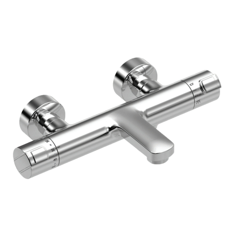
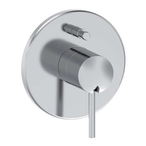
  9. SIMILOR KUGLER arwa-curveprime WI9.32076.100.000 User manual

SIMILOR KUGLER arwa-curveprime WI9.32076.100.000 User manual

DE/FR/IT/EN
Diese Anleitung muss dem Benutzer ausgehändigt werden. Garantie/Haftung nur
bei Montage gemäss Anleitung durch eine konzessionierte Fachkraft und gemäss
örtlicher Vorschriften.
Cette instruction doit être remise à l’utilisateur final. Garantie/responsabilité
uniquement assurées en cas de montage conforme au mode d’emploi, effectué
par un spécialiste concessionnaire et en fonction des directives locales.
Le presenti istruzioni devono essere consegnate all’utilizzatore. Garanzia/respon-
sabilità assicurate soltanto in caso di montaggio conforme alle istruzioni per l’uso
ed eseguito da uno specialista concessionario secondo le direttive locali.
This instruction must be given to the end-user. Guarantee/Liability only when
assembled by an approved specialist in accordance with the instructions and
local regulations.
DE
IT
EN
FR
arwa-curveprime® /arwa-twinprime®
DE/FR/IT/EN 2
Technische Daten
Données techniques
Dati tecnici
Technical data
Pressione di funzionamento consigliata:...2–4 bar
Pressione di funzionamento massima:........ 5 bar
Temperatura massima dell’acqua calda:.....80 °C
Temperatura consigliata per l’acqua calda: 65 °C
Si raccomanda di mantenere uguali le pressioni
«calda-fredda».
Attenzione: sciaquare le tubature prima di
installare il miscelatore. Nei modelli con flessibili,
mantenere fermo in rotazione il flessibile durante
il serraggio del dado di collegamento. Dopo il
montaggio aprire l’acqua e controllare il funzio-
namento. Verificare la tenuta della rubinetteria,
dei collegamenti e delle guarnizioni (controllo a
vista). Il corpo e il collo del miscelatore possono
diventare assai caldi. Installazione e manuten-
zione esclusivamente a cura di un installatore
concessionario secondo le direttive locali.
Garanzia: vedere le nostre condizioni generali di
vendita e di garanzia. Con riserva di modifiche
tecniche.
Empfohlener Betriebsdruck: ....................2–4 bar
Maximaler Betriebsdruck: ........................... 5 bar
Maximale Warmwassertemperatur..............80 °C
Empfohlene Warmwassertemperatur: .........65 °C
Gleicher Druck für Kalt- und Warmwasser wird
empfohlen.
Wichtig: Die Leitungen vor der Installation des
Mischers spülen. Bei den Modellen mit Flex-
schläuchen, den Schlauch beim Anziehen der
Mutter gegen Rotation gegenhalten. Nach der
Montage Wasserdruck geben und Funktionskon-
trolle durchführen. Dichtheit der Armatur und aller
Verbindungen überprüfen (Sichtkontrolle). Körper
und Auslauf des Mischers können heiss werden.
Die Installation und Wartung darf nur durch einen
nach den örtlichen Vorschriften konzessionierten
Installateur erfolgen.
Garantie: Siehe unsere Allgemeinen Verkaufs-
und Garantiebestimmungen. Technische Ände-
rungen vorbehalten.
Advised operating pressure: ....................2–4 bar
Maximum operating pressure: .................... 5 bar
Maximum temperature of hot water:...........80 °C
Advised temperature of hot water:..............65 °C
Equal “hot/cold” water pressure is recommended.
Caution: Rinse the conduits before installing the
mixer. On models with flexible hoses, hold the
hose to prevent it from rotating when tightening
the nut. After installation turn on the water and
check if the tap is functioning correctly. Check
the tap and all the connections for leaks (visual
check). The body and spout of the mixer can
become very hot. To be installed and maintained
only by an approved fitter according to local
instructions.
Guarantee: See our general sales and guaran-
tee conditions. Subject to technical changes.
Pression de service conseillée: ................2–4 bar
Pression de service maximale:.................... 5 bar
Température maximale de l’eau chaude:.....80 °C
Température de l’eau chaude conseillée: ....65 °C
Une égalité des pressions «chaude-froide» est
recommandée.
Attention: Rincer les conduites avant l’installa-
tion du mitigeur. Sur les modèles avec flexibles
d’alimentation, retenir le flexible en rotation lors
du serrage de l’écrou. Après installation, ouvrir
l’eau et contrôler le fonctionnement. Vérifier
l’étanchéité de la robinetterie et des joints
(contrôle visuel). Le corps et le goulot du mitigeur
peuvent devenir très chauds. Installation et entre-
tien uniquement par un installateur agréé selon
les directives locales.
Garantie: Voir nos conditions générales de
ventes et de garantie. Sous réserve de modifica-
tions techniques.
DE/FR/IT/EN 3
Nach dem Entfernen der drei
Kunststoffstopfen:
Die drei Sitze gut trocknen und
darauf achten, dass sie für die
Montage des Decors frei von
Schutt und Staub sind.
Après démontage des 3 bou-
chons en plastique:
Bien sécher les 3 logements et
veillez à ce qu’il n’y ait pas de
gravats qui obstruent les emplace-
ments de montage des décors.
Una volta smontati i 3 tappi
in plastica, far asciugare bene i
3 alloggi e assicurarsi che non ci
siano calcinacci ad ostacolare il
montaggio del rivestimento.
After removing the 3 plastic plugs:
Thoroughly dry the 3 housings
and ensure that there is no rubble
that could obstruct the decorative
trim mounting locations.
Unterputzeinbaukörper mit
drei blauen Stopfen
Modèle de corps à encastrer
avec 3 bouchons bleus
Modello di corpo da incasso
con 3 tappi blu.
Built in body model with 3 blue
plugs
Préparation du mur avant montage du décor. Les opérations ci-après sont réalisées
lorsque le mur fini est terminé et après coupure des eaux.
Preparazione del muro prima del montaggio della decorazione. Le operazioni di seguito illustrate
verranno effettuate una volta rifinito il muro e tolta l’acqua.
Vorbereitung der Wand vor der Montage des Decors. Die nachfolgenden Vorgänge
werden durchgeführt, wenn die Wand fertiggestellt und das Wasser abgestellt ist.
Preparation of the wall before fitting the decorative trim. The operations below are performed
when the finished wall is complete and after switching off the water supply.
DE/FR/IT/EN 4
Préparation du mur avant montage du décor. Les opérations ci-après sont réalisées
lorsque le mur fini est terminé et après coupure des eaux.
Preparazione del muro prima del montaggio della decorazione. Le operazioni di seguito illustrate
verranno effettuate una volta rifinito il muro e tolta l’acqua.
Vorbereitung der Wand vor der Montage des Decors. Die nachfolgenden Vorgänge
werden durchgeführt, wenn die Wand fertiggestellt und das Wasser abgestellt ist.
Preparation of the wall before fitting the decorative trim. The operations below are performed
when the finished wall is complete and after switching off the water supply.
– Scier avec soin les 3 manchons
et évacuer aux déchets les
coupes.
– Bien ébavurer le plastique à
l’intérieur du diamètre fileté.
– Les parties coupées ne doivent
en aucun cas dépasser, cela
compromettrait un bon placage
des rosaces de décorations
contre le mur fini.
– Carefully saw the 3 sleeves and
remove the debris from the cuts.
– Completely deburr the plastic
inside the threaded diameter.
– In no case must the cut parts
stick out, this would compro-
mise correct placing of the
decorative roses against the
finished wall.
– Die drei Muffen vorsichtig absä-
gen und die abgesägten Stücke
entsorgen.
– Den Kunststoff auf der In-
nenseite mit Gewinde sorgfältig
entgraten.
– Nach dem Absägen dürfen die
Muffen auf keinen Fall hervorste-
hen, da dies ein enges Anliegen
der Rosetten an der Wand
behindern würde.
– Segare con cura i 3 manicotti e
smaltire i residui.
– Sbavare attentamente la plastica
all’interno del diametro filettato.
– Le parti tagliate non devono
mai sporgere, perché questo
comprometterebbe il coretto
posizionamento dei rosoni dec-
orativi sul muro finito.
Unterputzeinbaukörper mit 3
beigefarbenen Muffen G1"
Modèle de corps à encastrer
avec 3 manchons G1" beiges
Modello di corpo da incasso
con 3 manicotti G1" beige
Built in body model with 3 G1"
beige sleeves
DE/FR/IT/EN 5
Après démontage des 3 bou-
chons en laiton:
Bien sécher les 3 logements et
veillez à ce qu’il n’y ait pas de
copeaux de plastique et gravats
qui obstruent les emplacements
de montage des décors.
After removing the 3 brass plugs:
Carefully dry the 3 housings and
ensure that there are no plastic
chips or rubble that could obstruct
the decorative trim mounting
locations.
Nach dem Entfernen der drei
Messingstopfen:
Die drei Sitze sorgfältig trocken
und darauf achten, dass sie für
die Montage des Decors frei von
Kunststoffspänen und Schutt und
Staub sind.
Una volta smontati i 3 tappi
in ottone, far asciugare bene i 3
alloggi e verificare che non ci siano
residui di plastica e calcinacci ad
ostacolare i punti di montaggio
delle decorazioni.
Préparation du mur avant montage du décor. Les opérations ci-après sont réalisées
lorsque le mur fini est terminé et après coupure des eaux.
Preparazione del muro prima del montaggio della decorazione. Le operazioni di seguito illustrate
verranno effettuate una volta rifinito il muro e tolta l’acqua.
Vorbereitung der Wand vor der Montage des Decors. Die nachfolgenden Vorgänge
werden durchgeführt, wenn die Wand fertiggestellt und das Wasser abgestellt ist.
Preparation of the wall before fitting the decorative trim. The operations below are performed
when the finished wall is complete and after cutting off the water.
Unterputzeinbaukörper mit 3
beigefarbenen Muffen G1"
Modèle de corps à encastrer
avec 3 manchons G1" beiges
Modello di corpo da incasso
con 3 manicotti G1" beige
Built in body model with 3 G1"
beige sleeves
DE/FR/IT/EN 6
Warmwasser
Eau chaude
Acqua calda
Hot water
Kaltwasser
Eau froide
Acqua fredda
Cold water
Montage der Keramikoberteile
Montage des chapeaux céramiques
Montaggio dei vitoni in ceramica
Fitting the ceramic headworks
DE/FR/IT/EN 7
Montage des Auslaufs
Montage du goulot
Montaggio del bocchettone
Fitting the spout
– Sorgen Sie für die Dichtigkeit
der Halterung des Auslaufs und
schrauben Sie diese bis zum
Anschlag in den Sitz.
– Nach der Montage des Auslaufs
ist das Wasser wieder anzustel-
len und die gesamte Baugruppe
auf Dichtigkeit zu überprüfen.
– Réaliser l’étanchéité du support
de goulot et le visser à fond
dans son logement.
– Après montage du goulot, re-
mettre la batterie sous pression
du réseau et vérifier l’étanchéité
générale de l’ensemble.
– Rendere impermeabile il suppor-
to del bocchettone e avvitarlo
fino in fondo nella sua sede.
– Una volta montato il bocchet-
tone, rimettere in pressione e
verificare la tenuta generale
dell’impianto.
– Seal the spout support and
screw it completely into its
housing.
– After fitting the spout, restore
mains pressure to the mixer unit
and check the general water
tightness of the assembly.
twinprime
curveprime
curveprime open
DE/FR/IT/EN 8
twinprime
curveprime
curveprime open
Montage der Griffe
Montage des poignées
Montaggio delle manopole
Fitting of the handles
Ausrichten der Griffe, siehe Seiten 10/11
Alignement des poignées, voir pages 10/11
Allineamento delle manopole, vedi pagine 10/11
Alignment of the handles, see pages 10/11
DE/FR/IT/EN 9
Die Griffe werden definitiv in horizontaler Stellung eingeklinkt, wenn sich die Oberteile in der geschlossenen
Stellung befinden. Für die endgültige Ausrichtung der Griffe siehe nächster Abschnitt.
Nach der endgültigen Montage des Decors der Griffe kann es in bestimmten Fällen vorkommen, dass nach
dem Einklinken des Griffes ein zu großes Spiel zwischen der Decor-Hülse und dem Griff sichtbar ist:
a) Schätzen Sie die Größe des Spiels mit Hilfe von Ausgleichsscheiben (1).
b) Nehmen Sie den Griff ab und entfernen Sie die Baugruppe (2) wieder.
c) Setzen Sie die erforderliche Anzahl Scheiben ein und montieren Sie die Baugruppe erneut.
Wichtig: In jedem Fall muss mindestens die Bundscheibe (3) eingesetzt werden, bevor die Decor-Hülse
auf das Oberteil geschraubt wird. Mit jedem Ausgleichsscheiben-Set kann ein Spiel von mind. 0,5 mm
bis max. 1,5 mm ausgeglichen werden. Der eingeklinkte Griff darf nach dem Ausgleichen des Spiels auf
keinen Fall am Decor scheuern.
Les poignées sont encliquetées définitivement en position horizontale lorsque les chapeaux sont en position
fermée. Pour le réglage final d’orientation des poignées, voir le chapitre suivant.
Après assemblage final des décors de poignées, dans certains cas, il se peut qu’après encliquetage de la
poignée, un jeu trop important soit visible entre la douille décor et la poignée:
a) Estimer ce jeu à l’aide des rondelles de compensation (1).
b) Démonter la poignée et dévisser à nouveau l’ensemble (2).
c) Insérer le nombre de rondelles nécessaires et remonter l’ensemble.
Important:
Toujours insérer au minimum la rondelle épaulée (3) avant de visser la douille décor sur le cha-
peau.
Chaque set de rondelles de compensation permet de réduire des jeux de 0,5 mm mini. à 1,5 mm
maxi. La poignée encliquetée ne doit en aucun cas frotter sur le décor après réglage du jeu.
Le manopole sono bloccate definitivamente in posizione orizzontale quando i vitoni sono in posizione chiusa.
Per la regolazione finale di orientamento delle manopole, vedi il capitolo successivo.
Effettuato l’assemblaggio finale delle decorazioni delle manopole, è possibile che in alcuni casi, una volta
bloccata la manopola, ci sia troppo giocco tra il porta-decorazione et la manopola:
a) Valutare l’entità del gioco con delle rondelle di compensazione (1).
b) Smontare la manopola e svitare di nuovo il tutto (2).
c) Inserire la quantita di rondelle necessarie e rimontare tutto.
Importante: inserire sempre la rondella di spallamento (3) prima di avvitare il porte-decorazione sui vitoni.
Ogni set di rondelle di compensazione consente di ridurre il gioco da un minimo di 0.5 mm a un massimo
di 1.5 mm. Una volta regolato il gioco, la manopola accoppiata non deve sfregare contro la decorazione.
The handles are definitively clicked into the horizontal position when the headworks are in the closed posi-
tion. For final adjustment of the handle orientation, see the following chapter.
In certain cases, after final assembly of the handles’ decorative trims and after clicking the handle into place,
an excessive gap can be visible between the decor sleeve and the handle:
a) Estimate this gap using the compensation washers (1).
b) Remove the handle and unscrew the assembly again (2).
c) Insert the number of washers needed and refit the assembly.
Important: Always insert the shouldered washer to the minimum (3) before screwing the decor sleeve
onto the headwork. Each set of compensation washers permits reduction in gap from 0.5 mm mini. to
1.5 mm max. There should be no friction between the snaped handle and the decor sleeve once the gap
has been adjusted. 
Montage der Griffe
Montage des poignées
Montaggio delle manopole
Fitting of the handles
DE/FR/IT/EN 10
Montage und Ausrichten der Griffe
Montage et alignement des poignées
Montaggio ed allineamento delle manopole
Fitting and alignment of the handles
– Vor der Einstellung zunächst prüfen, welche Art von Keramikoberteilen in Ihrem Unterputzkörper montiert sind (Typ A oder B).
– Es ist einfacher, wenn Ihre Armatur unter Druck steht um zu bestimmen, in welcher Bedienungsrichtung Ihre Griffe öffnen/schließen.
– Pour réaliser ce réglage, vérifier au préalable de quel type sont les chapeaux céramiques montés dans votre corps encastré (Typ A ou B).
– Cette opération sera facilitée si votre batterie est mise sous eaux afin de déterminer le sens d’ouverture/fermeture de vos poignées.
– Per realizzare questa regolazione, verificare prima il tipo di vitoni in ceramica montate sul corpo da incasso (tipo A o B).
– Questa operazione risulterà facilitata se il gruppo viene messo sott’acqua per determinare il senso di apertura/chiusura delle manopole.
– To make this adjustment, first check what type of ceramic headworks are fitted in your built in body (Type A or B).
– This operation will be easier if your mixer unit is connected to the water supply in order to determine the opening/closing directions
of your handles.
DE/FR/IT/EN 11
Ausrichten der Griffe
1) Geriffelten Einsatz (2) auf die Mitnehmereinheit (1) setzen
2) Schraube (3) um eineinhalb Umdrehungen festziehen
3) Griff (4) ohne einzuklinken (in beliebiger Position)
auf den Einsatz (2) setzen
4) Griff (4) bis zum Anschlag (in Schliessrichtung) drehen
– Typ A schliesst gegen den Uhrzeigersinn
– Typ B schliesst im Uhrzeigersinn
Wichtig: Die Einstellungen 5) bis 10) erfolgen, ohne die Griffe (4)
definitiv einzuklinken
5) Griff (4) wegnehmen und wie in der fig. 1 gezeigt positionieren
6) Winkel (A) in Grad abschätzen siehe fig. 2
7) Griff (4) wegnehmen und den geriffelten Einsatz (2) anheben,
bis er am Schraubenkopf einklinkt Distanz a)
8) Griff (4) sorgfältig ohne einzuklinken auf den Einsatz (2)
setzen Distanz b) (Riffelungen um etwa die Hälfte ihrer
Länge frei)
9) Das Ganze um die Anzahl Klicks (A) gleich den abgeschätzten
Graden (A) in Schliessrichtung drehen – siehe fig. 1
10) Griff (4) vollständig wegnehmen und horizontal ausgerichtet
wieder aufsetzen (darauf achten, den Warmwassergriff nicht
um 180° zurückzudrehen eine einzige Position gilt als
ausgerichtet)
Wenn der Winkel (A) nicht richtig geschätzt worden ist,
die Arbeitsgänge 5) bis 9) wiederholen, bis die Griffe (4)
genau ausgerichtet sind
Sobald der Griff (4) genau ausgerichtet ist, diesen wegnehmen und
die Schraube (3) ganz festziehen und den Griff (4)
definitiv am Einsatz (2) einklinken
Alignement des poignées
1) Introduire l’insert cannelé (2) sur l’entraîneur (1)
2) Serrer la vis (3) sur un tour et demi
3) Introduire la poignée (4) sur l’insert (2) sans l’encliqueter (en
position indifférente)
4) Tourner la poignée (4) jusqu’en butée (attention au sens de
fermeture)
–
Typ A se ferme dans le sens contraire des aiguilles d’une montre
– Typ B se ferme dans le sens des aiguilles d’une montre
Important: Les opérations de réglages 5) à 10) s’effectuent sans
encliqueter définitivement les poignées (4)
5) Ôter la poignée (4) et la positionner comme sur (fig. 1)
6) Estimer l’angle en degrés (A) voir (fig. 2)
7) Ôter la poignée (4) et soulever l’insert cannelé (2) jusqu’à
encliquetage sur la tête de vis distance a)
8) Poser délicatement sans l’encliqueter la poignée (4) sur
l’insert (2) distance b) (cannelures dégagées sur environ la
moitié de leur hauteur)
9) Faire tourner l’ensemble dans le sens de la fermeture d’un
nombre de clics (A) égal au nombre de degrés (A) estimés
(voir fig. 1)
10) Retirer complètement la poignée (4) puis la reposer alignée
horizontalement (attention à ne pas retourner la poignée d’eau
chaude de 180° une seule position est alignée)
Si l’angle (A) a été sous-estimé, recommencer les opérations 5) à 9)
jusqu’à alignement parfait des poignées (4)
Une fois la poignée (4) parfaitement alignée, l’ôter pour serrer la vis
(3) à fond et l’encliqueter définitivement sur l’insert (2)
Alignment of the handles
1) Place the grooved insert (2) onto the driving sleeve (1)
2) Tighten the screw (3) a turn and a half
3) Place the handle (4) on the insert (2) (in any position) without
engaging it on the ratchet
4) Turn the handle (4) up to the stop (in the OFF direction)
– Typ A turns off anticlockwise
– Typ B turns off clockwise
Important: Adjustment operations 5) to 10) are carried out without
finally engaging the handles on the ratchet (4)
5) Remove the handle (4) and position it as in (fig. 1)
6) Estimate the angle (A) in degrees see (fig. 2)
7) Remove the handle (4) and raise the grooved insert (2) until it
engages on the screw head distance (a)
8) Delicately place the handle (4) on the insert (2) distance
b) without engaging it (leave about half the height of the grooves
exposed)
9) Turn the whole assembly in the OFF direction for a number of
clicks (A) equal to the estimated number of degrees (A)
(see fig. 1)
10) Completely remove the handle (4) then replace it horizontally
aligned (Take care not to turn the hot water handle through
180° only one position is aligned)
If angle (A) was underestimated, restart operations 5) to 9) until the
handles (4) are perfectly aligned
Once the handle (4) is perfectly aligned, remove it to tighten the
screw (3) and finally click it onto the insert (2)
Allineamento delle manopole
1) Infilare sul dispositivo di collegamento (1) l’inserto scanalato (2)
2) Stringere la vite (3) di un giro e mezzo
3) Infilare la manopola (4) sull’inserto (2) senza innestarla nell’arpio-
nismo (in posizione indifferente)
4) Girare la manopola (4) fino all’arresto (attenzione al senso
di chiusura)
– Typ A si chiude in senso antiorario
– Typ B si chiude in senso orario
Importante: Le operazioni di regolazione da 5) a 10) si eseguono
senza innestare definitivamente le manopole (4) nell’arpioni-
smo
5) Togliere la manopola (4) e posizionarla come indicato nella fig. 1
6) Valutare l’angolo in gradi (A) vedi fig. 2
7) Togliere la manopola (4) e sollevare l’inserto scanalato (2) finché
si innesta sulla testa della vite distanza a)
8) Posare delicatamente la manopola (4) sull’inserto (2) senza
innestarla nell’arpionismo (scanalature libere per circa la
metà della loro altezza)
9) Fare girare il tutto nel senso di chiusura di un numero di clic (A)
pari al numero di gradi stimati (A) (vedi fig. 1)
10) Togliere completamente la manopola (4) e poi rimetterla allineata
orizzontalmente (Attenzione a non girare la manopola dell’acqua
calda di 180° una sola posizione è allineata)
Se l’angolo (A) è stato sottovalutato, ripetere le operazioni da
5) a 9) finché le manopole (4) sono perfettamente allineate
Una volta che la manopola (4) è perfettamente allineata, toglierla per
serrare a fondo la vite (3) e poi innestarla definitivamente sull’inserto (2)
Montage und Ausrichten der Griffe
Montage et alignement des poignées
Montaggio ed allineamento delle manopole
Fitting and alignment of the handles
735.356-416
DE/FR/IT/EN
Similor AG
Wahlenstrasse 46, CH-4242 Laufen
Customer Service CH 0848000166
Tel. +41 (0)61 765 73 33, Fax +41 (0)61 765 73 34
www.similorgroup.com
[email protected]
Similor Kugler, arwa and Sanimatic are trademarks of the SimilorGroup
La robinetterie SimilorGroup est un produit de
haute qualité. Afin de maintenir la beauté de sa
surface, il est nécessaire d’observer les indications
suivantes: lorsque la robinetterie est légèrement
sale, il est recommandé de la nettoyer avec
de l’eau et du savon. Il est important de rincer
immédiatement la robinetterie à l’eau froide et de
l’essuyer avec un chiffon doux. N’utilisez jamais
de détergents granuleux, de produits corrosifs ou
d’acides agressifs.
SimilorGroup-Armaturen sind Qualitätsprodukte.
Um die Schönheit der hochwertigen Oberfläche
beizubehalten, sind folgende Hinweise zu beach-
ten: Bei leichter Verschmutzung, Armaturen mit
Seifenwasser reinigen, sofort mit kaltem Wasser
nachspülen und einem weichen Tuch nachpolieren.
Verwenden Sie generell keine sandhaltigen Putz-
mittel, korrosive Produkte oder agressive Säuren.
La rubinetteria SimilorGroup è un prodotto di alta
qualità. Per mantenere la bellezza della loro super-
ficie è necessario attenersi alle seguenti indicazioni:
Se la rubinetteria è solo leggermente sporca, basta
pulirla con acqua fredda e sapone e sciacquarla.
Quindi occorre asciugarla con un panno morbido.
Non utilizzate alcun detersivo granuloso, prodotti
corrosivi o acidi aggressivi.
SimilorGroup taps are high quality products. To
ensure that they remain in pristine condition, ple-
ase observe the following instructions: For routine
cleaning, wash the tap with soapy water. The tap
must be rinsed with cold water afterwards and
polish with a soft cloth. Never use granular deter-
gents, corrosive products or powerful acids.
Pflege der Oberfläche
Entretien de la surface
Manutenzione della superficie
Surface care

This manual suits for next models

1

Other SIMILOR KUGLER Plumbing Product manuals

SIMILOR KUGLER Sanimatic Arwa Outdoor WI 7 70628 441 195 User manual

SIMILOR KUGLER

SIMILOR KUGLER Sanimatic Arwa Outdoor WI 7 70628 441 195 User manual

SIMILOR KUGLER SK Citypro WI 5 00950 100 000 User manual

SIMILOR KUGLER

SIMILOR KUGLER SK Citypro WI 5 00950 100 000 User manual

SIMILOR KUGLER Laufen Sanimatic Simibox User manual

SIMILOR KUGLER

SIMILOR KUGLER Laufen Sanimatic Simibox User manual

SIMILOR KUGLER Arwa Sanimatic Touchboard WI 7 70341 101 000 User manual

SIMILOR KUGLER

SIMILOR KUGLER Arwa Sanimatic Touchboard WI 7 70341 101 000 User manual

SIMILOR KUGLER arwa Simibox 1 Point User manual

SIMILOR KUGLER

SIMILOR KUGLER arwa Simibox 1 Point User manual

SIMILOR KUGLER arwa-twinplus User manual

SIMILOR KUGLER

SIMILOR KUGLER arwa-twinplus User manual

SIMILOR KUGLER Arwa Sanimatic Easytouch-N User manual

SIMILOR KUGLER

SIMILOR KUGLER Arwa Sanimatic Easytouch-N User manual

SIMILOR KUGLER Arwa Simibox 2 Point User manual

SIMILOR KUGLER

SIMILOR KUGLER Arwa Simibox 2 Point User manual

SIMILOR KUGLER arwa-class M WI9.40080.100.085 User manual

SIMILOR KUGLER

SIMILOR KUGLER arwa-class M WI9.40080.100.085 User manual

SIMILOR KUGLER Sanimatic arwa-twin User manual

SIMILOR KUGLER

SIMILOR KUGLER Sanimatic arwa-twin User manual

SIMILOR KUGLER Arwa Sanimatic Twintronic WI 7 07023 100 000 User manual

SIMILOR KUGLER

SIMILOR KUGLER Arwa Sanimatic Twintronic WI 7 07023 100 000 User manual

SIMILOR KUGLER Arwa Sanimatic Multistation 7.70607 User manual

SIMILOR KUGLER

SIMILOR KUGLER Arwa Sanimatic Multistation 7.70607 User manual

SIMILOR KUGLER arwa-curveplus WI9.05250.100.000 User manual

SIMILOR KUGLER

SIMILOR KUGLER arwa-curveplus WI9.05250.100.000 User manual

SIMILOR KUGLER Simibox User manual

SIMILOR KUGLER

SIMILOR KUGLER Simibox User manual

SIMILOR KUGLER arwa-twinprime tronic WI9.08664.100.000 User manual

SIMILOR KUGLER

SIMILOR KUGLER arwa-twinprime tronic WI9.08664.100.000 User manual

SIMILOR KUGLER Arwa Sanimatic Inwalltouch WI 7 70001 100... User manual

SIMILOR KUGLER

SIMILOR KUGLER Arwa Sanimatic Inwalltouch WI 7 70001 100... User manual

SIMILOR KUGLER Arwa Sanimatic Inwalltouch 7.70008 User manual

SIMILOR KUGLER

SIMILOR KUGLER Arwa Sanimatic Inwalltouch 7.70008 User manual

SIMILOR KUGLER arwa-curveprime WI9.32050.100.00 User manual

SIMILOR KUGLER

SIMILOR KUGLER arwa-curveprime WI9.32050.100.00 User manual

SIMILOR KUGLER arwa-surf WI9.10500.100.001 User manual

SIMILOR KUGLER

SIMILOR KUGLER arwa-surf WI9.10500.100.001 User manual

SIMILOR KUGLER Sanimatic arwa-curveprime WI9.32010.100.000 User manual

SIMILOR KUGLER

SIMILOR KUGLER Sanimatic arwa-curveprime WI9.32010.100.000 User manual

Popular Plumbing Product manuals by other brands

Moen ROTHBURY T923 Illustrate parts list

Moen

Moen ROTHBURY T923 Illustrate parts list

ZUCCHETTI PAN ZP8729 Instruction for the installation

ZUCCHETTI

ZUCCHETTI PAN ZP8729 Instruction for the installation

BEMIS NextStep CPT Installation instruction

BEMIS

BEMIS NextStep CPT Installation instruction

Mira Mode instructions

Mira

Mira Mode instructions

Hans Grohe AXOR Citterio M 34435000 Assembly instruction

Hans Grohe

Hans Grohe AXOR Citterio M 34435000 Assembly instruction

Oras Ventura 8041 Installation and maintenance guide

Oras

Oras Ventura 8041 Installation and maintenance guide

American Standard Culinaire Single Control Kitchen Faucet with Hi-Flow Spout... installation instructions

American Standard

American Standard Culinaire Single Control Kitchen Faucet with Hi-Flow Spout... installation instructions

Balmani BMSS-PVD installation guide

Balmani

Balmani BMSS-PVD installation guide

KWC Geneva S.10.D4.01 Specification sheet

KWC

KWC Geneva S.10.D4.01 Specification sheet

Hans Grohe AXOR Starck Nature 240 1 jet 12670 Series Assembly instructions

Hans Grohe

Hans Grohe AXOR Starck Nature 240 1 jet 12670 Series Assembly instructions

Hans Grohe Metropol 32543 Series Assembly instructions

Hans Grohe

Hans Grohe Metropol 32543 Series Assembly instructions

Sanela SLPN 04CB Mounting instructions

Sanela

Sanela SLPN 04CB Mounting instructions

Lefroy Brooks 1135 installation guide

Lefroy Brooks

Lefroy Brooks 1135 installation guide

Toto TN74-2X Installation and instruction manual

Toto

Toto TN74-2X Installation and instruction manual

IKEA RUTSJON manual

IKEA

IKEA RUTSJON manual

Riobel PFTQ12T installation guide

Riobel

Riobel PFTQ12T installation guide

Bradley S19294 Series Installation

Bradley

Bradley S19294 Series Installation

BEJOAN X3-US Series instructions

BEJOAN

BEJOAN X3-US Series instructions

manuals.online logo
manuals.online logoBrands
  • About & Mission
  • Contact us
  • Privacy Policy
  • Terms and Conditions

Copyright 2025 Manuals.Online. All Rights Reserved.