manuals.online logo
Brands
  1. Home
  2. •
  3. Brands
  4. •
  5. Simplex
  6. •
  7. Fire Alarm
  8. •
  9. Simplex 4090-9001 User manual

Simplex 4090-9001 User manual

Mechanically Installing the Supervised IAM
Install the Supervised IAM into a UL Listed single-gang, 4-inch square, or 4-inch octagonal electrical box
(not supplied) using Figure 4 as a reference. Mount the Supervised IAM to the electrical box as follows:
1. Insert the Supervised IAM into the electrical box; the attached field wiring holds the Supervised IAM
in place inside the electrical box.
2. Secure the cover to the back box using the two #6/32 flathead screws.
Note: Simplex offers semi-flush and surface covers (ordered separately) with a light pipe. The cover(s)
with light pipe allow viewing of the communications LED without taking the cover off. Installation
of the 4090-9806 semi-flush cover and 4090-9807 surface cover are detailed in publication 4090
IDNet

Semi-Flush/Surface Covers and IAM Bracket Installation Instruction (574-796).
Figure 4. Supervised IAM Back Box Installation
4090-9001 Supervised IAM
Installation Instructions
574-331
Rev. E
574-331
Rev. E
2000 Simplex Time Recorder Co., Westminster, MA 01441-0001
All specifications and other information shown were current as of publication, and are subject to change without notice.
IDNetis a trademark of the Simplex Time Recorder Company.
MAPNET IICommunication Net is protected by U.S. Patent No.4,796,025.
UL Listed
Single-Gang
Electrical Box
(Not Supplied)
Cover
(Not Supplied)
Field Wiring
4090-9001
Supervised IAM
Assembly
#6/32 Flathead Screw
(Not Supplied)
Cautions and Warnings
DO NOT INSTALL ANY SIMPLEX PRODUCT THAT APPEARS DAMAGED. Upon unpacking
your Simplex product, inspect the contents of the carton for shipping damage. If damage is apparent,
immediately file a claim with the carrier and notify Simplex.
ELECTRICAL HAZARD - Disconnect electrical power when making any internal adjustments or repairs.
Servicing should be performed by qualified Simplex Representatives.
STATIC HAZARD - Static electricity can damage components. Ground yourself before opening or
installing components.
Introduction
IDNet
The 4090-9001 Supervised Individual Addressable Module (IAM) provide four-state status information
(NORMAL, OPEN, CURRENT-LIMITED, and SHORT) to the 4010 Fire Alarm Control Panel (FACP)
via the IDNetchannel. The IDNet channel provides the communication link between Supervised IAM
and 4010 FACP and powers the entire IAM circuitry. A typical application for this module would be to
monitor a waterflow switch.
MAPNET II
The 4090-9001 Supervised IAM provides three-state status information (NORMAL, OPEN, and ALARM)
to the host FACP via the MAPNET II channel. Applications that require current limit sensing are not
compatible with MAPNET II channels (Tamper/Waterflow on the same IAM, Manual release/abort, etc.).
The MAPNET II channel provides the communication link between the Supervised IAM and host 4100, or
4120, or 4020 FACP and powers the entire IAM circuitry.
Installation
Supervised IAM installation consists of the following:
• Setting the Supervised IAMs address
• Making electrical connections to the Supervised IAM
• Mechanically installing the Supervised IAM
Front View Rear View
Label
DIP Switch
(Under Re-sealable Label)
LED
Terminal
Note: The LED flashes approximately once every three seconds to indicate valid
communications with the FACP.
Figure 1. Supervised IAM Installation
firealarmresources.com
Making Electrical Connections to the Supervised IAM
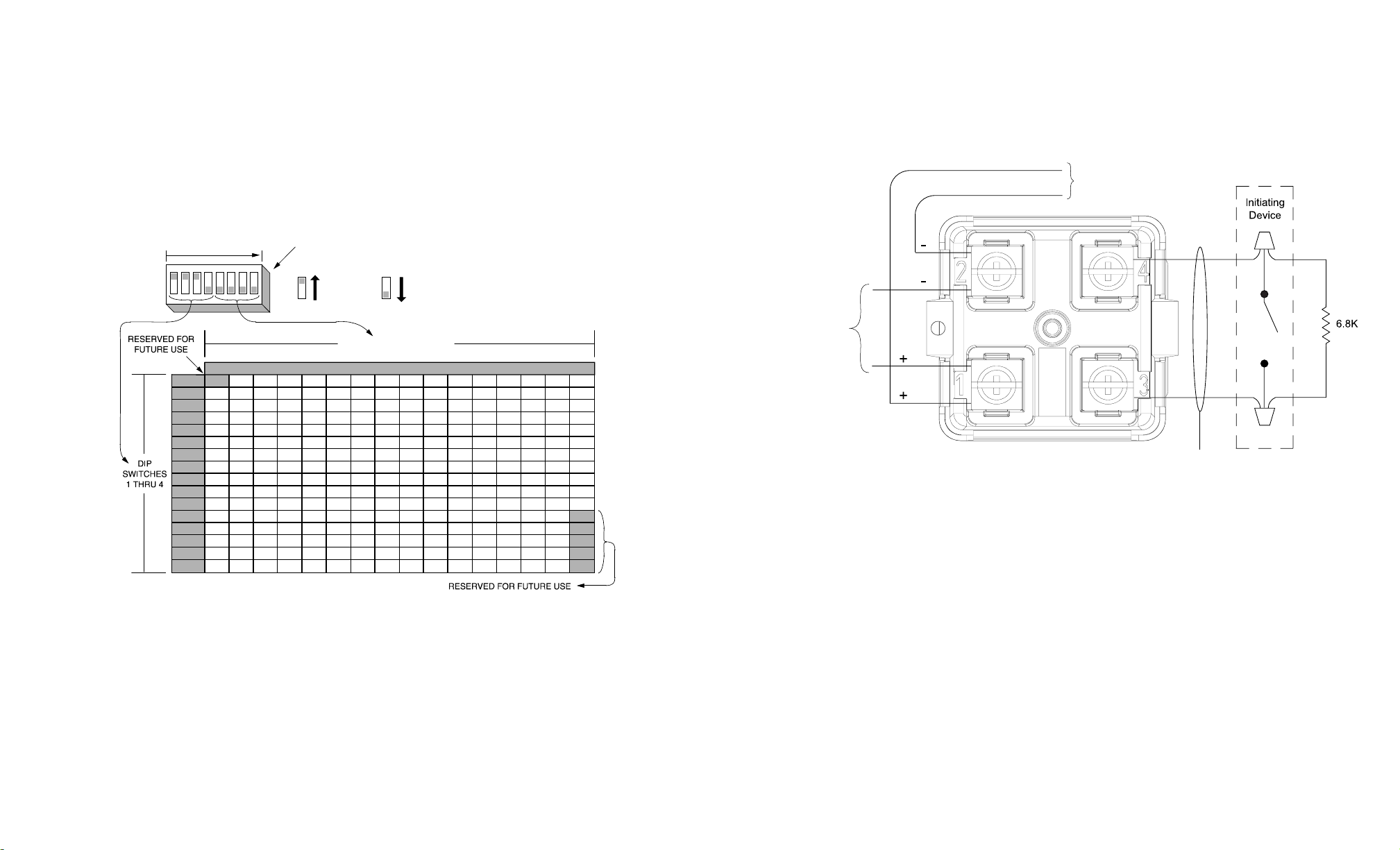
Input and output signals connect to the Supervised IAM via the terminals (1-4) as illustrated in
Figure 1. Terminal connections for the IAM are illustrated in Figure 3.
CAUTION: Do not loop wire under terminals. Break wire runs to provide supervision.
Notes:
1. When connecting two wires to one terminal, position one wire on each side of the terminal screw.
2. IDNet and MAPNET II lines are 18 AWG twisted pair (shield recommended).
3. Maximum allowable run from FACP to farthest device not to exceed 2500 feet. Maximum total wire
(including all T-Taps) from FACP is 10000 feet.
4. Maximum wire length is 400 feet, #18 AWG.
5. Refer to Field Wiring Diagram 842-073 for further information on wiring Supervised IAMs to IDNet.
Refer to Field Wiring Diagrams 841-804 or 841-996 for further information on wiring Supervised
IAMs to MAPNET II. IDNet and MAPNET II wiring are supervised and power-limited.
Figure 3. Supervised IAM Connections
32
Setting the Supervised IAMs Address
Note: The IDNet channel (4010 FACP only) supports address codes 1 through 250. The MAPNET II channel
(4100, or 4120, or 4020 FACP) supports address codes 1 through 127.
Each Supervised IAM has a unique address. The address of the IAM is set via an eight position DIP switch
(Figure 1), DIP switch position 1 is the least significant bit (LSB) and position 8 is the most significant bit
(MSB). Set the IAMs address using Figure 2 as reference. Use a small screwdriver or pen to set the switches.
The device address for the Supervised IAM should be written on the re-sealable label, this information provides
an aid in troubleshooting the system.
Note: DIP switch in “1” position is “ON” while DIP switch in “0” position is “OFF.”
0000 1000 0100 1100 0010 1010 0110 1110 0001 1001 0101 1101 0011 1011 0111 1111
0000 0 16 32 48 64 80 96 112 128 144 160 176 192 208 224 240
1000 1 17 33 49 65 81 97 113 129 145 161 177 193 209 225 241
0100 2 18 34 50 66 82 98 114 130 146 162 178 194 210 226 242
1100 3 19 35 51 67 83 99 115 131 147 163 179 195 211 227 243
0010 4 20 36 52 68 84 100 116 132 148 164 180 196 212 228 244
1010 5 21 37 53 69 85 101 117 133 149 165 181 197 213 229 245
0110 6 22 38 54 70 86 102 118 134 150 166 182 198 214 230 246
1110 7 23 39 55 71 87 103 119 135 151 167 183 199 215 231 247
0001 8 24 40 56 72 88 104 120 136 152 168 184 200 216 232 248
1001 9 25 41 57 73 89 105 121 137 153 169 185 201 217 233 249
0101 10 26 42 58 74 90 106 122 138 154 170 186 202 218 234 250
1101 11 27 43 59 75 91 107 123 139 155 171 187 203 219 235
0011 12 28 44 60 76 92 108 124 140 156 172 188 204 220 236
1011 13 29 45 61 77 93 109 125 141 157 173 189 205 221 237
0111 14 30 46 62 78 94 110 126 142 158 174 190 206 222 238
15 31 47 63 79 95 111 127 143 159 175 191 207 223 239
LSB MSB
12345678
1111
DIP SWITCHES 5 THRU 8
ON
OFF 1 = ON 0 = OFF
251
252
253
254
255
DIPSWITCH IS SHOWN SET AT ADDRESS 7
.
Figure 2. Supervised IAM Address Chart
4010 FACP (IDNet Channel)
Configure the Supervised IAM to the 4010 panel using the 4010 Fire Alarm - Installation and Programming
(574-187) and 4010 Fire Alarm - Installing, Operating, and Programming Instructions (574-052). Refer to
4010 panel label 526-444 for appropriate revision of the instructions to be used.
4100/4120/4020 FACP (MAPNET II Channel)
Configure the Supervised IAM to the host FACP using the 4100, 4120, or 4020 Programmer’s Report. The
Supervised IAM address and location must match up with the address listed in the specification sheets of the
4100, 4120, or 4020 Programmer’s Report.
MAPNET II supports address codes 1 through 127 only.
MAPNET II/IDNET
(See Notes)
MAPNET II/IDNET
To Next Device
(See Note 5) See Note 4
firealarmresources.com

Other Simplex Fire Alarm manuals

Simplex SafeLINC 4100U User manual

Simplex

Simplex SafeLINC 4100U User manual

Simplex MINIPLEX 4100-9600 User manual

Simplex

Simplex MINIPLEX 4100-9600 User manual

Simplex 4100ESi User manual

Simplex

Simplex 4100ESi User manual

Simplex 49VO-WRF User manual

Simplex

Simplex 49VO-WRF User manual

Simplex SafeLINC 4100 User manual

Simplex

Simplex SafeLINC 4100 User manual

Simplex 49SVC-CWFIRE User manual

Simplex

Simplex 49SVC-CWFIRE User manual

Simplex 4098-5217 User manual

Simplex

Simplex 4098-5217 User manual

Simplex 4002 User manual

Simplex

Simplex 4002 User manual

Simplex 4010 User manual

Simplex

Simplex 4010 User manual

Simplex LifeAlarm 4005 Series Installation manual

Simplex

Simplex LifeAlarm 4005 Series Installation manual

Simplex SafeLINC 4100U User guide

Simplex

Simplex SafeLINC 4100U User guide

Simplex 4010ES User manual

Simplex

Simplex 4010ES User manual

Simplex 4606-9102 User manual

Simplex

Simplex 4606-9102 User manual

Simplex SafeLINC 4020 User manual

Simplex

Simplex SafeLINC 4020 User manual

Simplex 4100-1314 User manual

Simplex

Simplex 4100-1314 User manual

Simplex 4100ES-S1 Maintenance and service guide

Simplex

Simplex 4100ES-S1 Maintenance and service guide

Simplex 6351 Manual

Simplex

Simplex 6351 Manual

Simplex 4007ES Panels User manual

Simplex

Simplex 4007ES Panels User manual

Simplex InfoAlarm 4100U User manual

Simplex

Simplex InfoAlarm 4100U User manual

Simplex 4002 Life Alarm Operating instructions

Simplex

Simplex 4002 Life Alarm Operating instructions

Simplex IDNet 4099-9801C User manual

Simplex

Simplex IDNet 4099-9801C User manual

Simplex 4098 Instructions for use

Simplex

Simplex 4098 Instructions for use

Simplex SafeLINC 4100 Operating instructions

Simplex

Simplex SafeLINC 4100 Operating instructions

Simplex MINIPLEX 4100ES Series User manual

Simplex

Simplex MINIPLEX 4100ES Series User manual

Popular Fire Alarm manuals by other brands

olympia electronics BSR-2104/MAR Operation and installation manual

olympia electronics

olympia electronics BSR-2104/MAR Operation and installation manual

Isimet FLA Series Installation, Operations, Start-up and Maintenance Instructions

Isimet

Isimet FLA Series Installation, Operations, Start-up and Maintenance Instructions

Shield D-A412 user manual

Shield

Shield D-A412 user manual

Bosch B925F installation guide

Bosch

Bosch B925F installation guide

E2S BExCP3B-PB instruction manual

E2S

E2S BExCP3B-PB instruction manual

C-TEC CAST ZFP Quick start user guide

C-TEC

C-TEC CAST ZFP Quick start user guide

E2S GNExCP7-PB-S instruction manual

E2S

E2S GNExCP7-PB-S instruction manual

Tyco F4000 Lcd operator's manual

Tyco

Tyco F4000 Lcd operator's manual

FireFlex TOTALPAC 3 Owner's operation & maintenance manual

FireFlex

FireFlex TOTALPAC 3 Owner's operation & maintenance manual

Pro-tec Algo-Tec 6400 quick start guide

Pro-tec

Pro-tec Algo-Tec 6400 quick start guide

Notifier CAB-5 Product installation document

Notifier

Notifier CAB-5 Product installation document

Ziton ZP2-A Series Quick operation guide

Ziton

Ziton ZP2-A Series Quick operation guide

ASENWARE AW-FP100 Series manual

ASENWARE

ASENWARE AW-FP100 Series manual

Honeywell Fire-Lite Alarms BG-12S manual

Honeywell

Honeywell Fire-Lite Alarms BG-12S manual

Teknim TFS-1183R installation manual

Teknim

Teknim TFS-1183R installation manual

Fireye SB Series manual

Fireye

Fireye SB Series manual

Aritech FP2000 reference guide

Aritech

Aritech FP2000 reference guide

Wheelock RSS-2415C installation instructions

Wheelock

Wheelock RSS-2415C installation instructions

manuals.online logo
manuals.online logoBrands
  • About & Mission
  • Contact us
  • Privacy Policy
  • Terms and Conditions

Copyright 2025 Manuals.Online. All Rights Reserved.