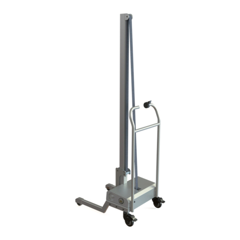
Simpro QUIKSTAK QS10MM User manual

User Manual // Quikstak QS10MM
Original Instructions // English // v52.0 // April 2022
USER MANUAL

Copyright © 2022 Simpro Handling Equipment Ltd.
No part of this document may be reproduced or transmitted in any form or by any means,
electronic, mechanical, photocopying, recording, or otherwise, without the written
permission of Simpro Handling Equipment Ltd.
For the purposes of standards compliance and international conformity, this document uses
Système International (SI) units. These may be converted to Imperial units as follows:
1 kilogram (kg) = 2.2 pounds (lb)
1 metre (m) = 1000 millimetres (mm) = 39.37 inches (in) = 3.28 feet (ft) = 1.09 yards (yd)
The following stylistic conventions are used throughout this document:
Point of interest
Safety hazard
§Internal cross-reference (hyperlink in PDF edition)
Simpro Partcode (hyperlink in PDF edition)
Errors in this document should be reported to info@simpro.world

User Manual // Quikstak QS10MM
Original Instructions // English // v52.0 // April 2022 // Page 2

Contents
1. Product Overview ......................................................................................................................... 5
1.1 Key features ......................................................................................................................................... 6
1.2 Construction ........................................................................................................................................ 6
1.3 Mechanism .......................................................................................................................................... 6
1.4 Rating plate ......................................................................................................................................... 6
1.5 Safe Lifting Capacity .......................................................................................................................... 7
1.6 Service life ............................................................................................................................................ 7
1.7 Noise emissions .................................................................................................................................... 7
1.8 Environmental limitations.................................................................................................................... 7
1.9 Notes..................................................................................................................................................... 8
2. Operating Instructions .................................................................................................................. 9
2.1 Identification of controls..................................................................................................................... 9
2.1.1 Tiller controls...................................................................................................................................................... 9
2.1.2 Fascia controls................................................................................................................................................ 10
2.1.3 Quikstak controls ............................................................................................................................................ 10
2.2 Before use .......................................................................................................................................... 11
2.3 Moving the Quikstak ......................................................................................................................... 11
2.3.1 Driving ............................................................................................................................................................. 11
2.3.2 Steering ........................................................................................................................................................... 12
2.3.3 Braking ............................................................................................................................................................ 12
2.3.4 Towing............................................................................................................................................................. 12
2.4 Handling pallets................................................................................................................................. 12
2.5 Using the Quikstak height-levelling system ..................................................................................... 13
2.5.1 Stacking goods...............................................................................................................................................13
2.5.2 De-stacking goods......................................................................................................................................... 14
2.6 Parking the stacker............................................................................................................................ 15
2.7 Charging the batteries ..................................................................................................................... 15
3. Operating Norms.........................................................................................................................16
4. Care and Maintenance.............................................................................................................19
4.1 Quick Troubleshooting Guide .......................................................................................................... 19
4.2 Cleaning............................................................................................................................................. 19
4.3 Removing the outer cover ............................................................................................................... 20
4.4 Electrical System................................................................................................................................ 20
4.4.1 International conformance...........................................................................................................................20
4.4.2 Batteries .......................................................................................................................................................... 20
4.4.3 Battery indicator............................................................................................................................................. 21
4.4.4 Battery charger .............................................................................................................................................. 21
4.4.5 Charging lead ................................................................................................................................................ 22
4.4.6 Emergency Stop............................................................................................................................................. 22
4.4.7 Fuses ................................................................................................................................................................ 22
4.4.8 Traction controller .......................................................................................................................................... 23
4.4.9 Wiring diagram............................................................................................................................................... 25

User Manual // Quikstak QS10MM
Original Instructions // English // v52.0 // April 2022 // Page 4
4.5 Lift & Hydraulic Systems..................................................................................................................... 26
4.5.1 Hydraulic fluid................................................................................................................................................. 26
4.5.2 Powerpack ..................................................................................................................................................... 26
4.5.3 Lift motor ......................................................................................................................................................... 26
4.5.4 Control valves................................................................................................................................................. 26
4.5.5 Lift ram.............................................................................................................................................................27
4.5.6 Roller chain .....................................................................................................................................................27
4.5.7 Forks................................................................................................................................................................. 28
4.6 Drive & Mechanical Systems............................................................................................................ 28
4.6.1 Drive motor ..................................................................................................................................................... 28
4.6.2 Gearbox.......................................................................................................................................................... 28
4.6.3 Electromagnetic brake.................................................................................................................................. 29
4.6.4 Wheels & bearings ......................................................................................................................................... 29
4.6.5 Straddle legs................................................................................................................................................... 29
4.7 Quikstak Height-Levelling System .................................................................................................... 30
4.7.1 Control panel ................................................................................................................................................. 30
4.7.2 PLC .................................................................................................................................................................. 30
4.7.3 Laser sensor..................................................................................................................................................... 30
4.7.4 LED strobe light ............................................................................................................................................... 30
4.8 Preventative Maintenance Inspections.......................................................................................... 31
4.8.1 Pre-inspection checklist ................................................................................................................................. 31
4.8.2 Inspection checklist........................................................................................................................................31
4.8.3 Inspection log sheets ..................................................................................................................................... 33
5. Handling, Transport & Storage................................................................................................... 37
5.1 Assembly ............................................................................................................................................ 37
5.2 Jacking up ......................................................................................................................................... 37
5.3 Lifting .................................................................................................................................................. 37
5.4 Transportation.................................................................................................................................... 37
5.5 Storage............................................................................................................................................... 38
6. Safety Assessment ....................................................................................................................... 39
6.1 Safety features................................................................................................................................... 39
6.2 Reasonably foreseeable misuse ...................................................................................................... 39
6.3 ISO12100 Hazard and Risk Assessment Guide ................................................................................ 39
6.3.1 The ISO12100 risk assessment model............................................................................................................. 40
6.3.2 Identified Hazards .......................................................................................................................................... 41
6.3.3 Residual Hazards ............................................................................................................................................ 44
7. Spare Parts ................................................................................................................................... 45
8. Technical Data ............................................................................................................................47
9. Warranty....................................................................................................................................... 49

1. Product Overview
Congratulations on your purchase of a Quikstak® QS10MM pallet stacker. Based on
technology patented by Simpro in 1994, a Quikstak is much more than just another pallet
stacker –it is a powerful, smart materials-handling solution.
With the QS10MM, Simpro has provided a number of improvements over the original “smart-
stacker” models. Produced in partnership with EP Equipment, every QS10MM is self-propelled
as standard, with a unique ‘monomast’design providing an unrestricted field of view.
The QS10MM height-levelling feature is based on laser technology.
When turned on, the laser sensor continuously measures the height
of product stacked on the Quikstak forks. This data is passed to a
PLC, which automatically raises or lowers the forks to maintain the
'stacking height' at an ergonomic level, even as product is added
or removed.
With its innovative design, superb visibility, and dual-mode laser
levelling, the QS10MM is the smartest Quikstak yet.

User Manual // Quikstak QS10MM
Original Instructions // English // v52.0 // April 2022 // Page 6
1.1 Key features
Key features of the Quikstak QS10MM include:
1. A laser height-levelling function controlled by PLC.
2. A safe lifting capacity of 1000kg.
3. A maximum lift height of 1900mm
4. An electro-hydraulic lifting mechanism.
5. Maintenance-free gel batteries with an onboard charger.
6. A self-propelled drive function with regenerative braking.
7. An industry-standard Curtis 1212 traction controller.
8. Adjustable outriggers and forks, compatible with all types of pallet.
9. A monomast design affording excellent visibility.
1.2 Construction
The Quikstak QS10MM consists of a steel frame with one vertical mast and two stabilizing
outrigger legs each with two load wheels, a Class 2 fork carriage, two forks, one hydraulic
ram, roller chain, guarding, control tiller with controls, one steered drive wheel and one
balance castor, a drive motor and gearbox, a hydraulic powerpack, batteries, electronic
control systems and a powerpack cover.
1.3 Mechanism
When the LIFT circuit is activated (either by manual control input or BY the PLC), the
powerpack pumps hydraulic fluid into the lift ram, making it extend. This pulls on an
arrangement of chains, causing the fork carriage to travel vertically in the mast. When the
LOWER circuit is activated, a valve allows the hydraulic fluid to return to the reservoir,
lowering the forks.
Electrical, hydraulic, and mechanical control systems allow the operator to lift and lower the
forks in a controlled manner. An electric drive system allows the machine to be moved and
steered easily, even when carrying heavy loads.
1.4 Rating plate
Item
Description
1
Manufacturer
2
Truck Type
3
Load capacity (kg)
4
Rated load centre
5
Fork width
6
Fork length
7
Fork height
8
Battery capacity
9
Service weight
10
Serial number
Figure 1

1.5 Safe Lifting Capacity
The rated Safe Lifting Capacity of the Quikstak is 1000kg at 600mm load centre. This means
that if the load centre is 600mm or less, a 1-tonne pallet can be lifted to the maximum height
of 1.9 metres. If the load centre is beyond 600mm, the load capacity is progressively derated
as illustrated by Figure 2.
Safe Lifting Capacity refers to the weight
in kilograms of the pallet, any items on
the pallet, and any other objects which
have been placed on the forks.
Load Centre refers to the distance in
millimetres from the face of the forks to
the load’s Centre of Gravity.
To identify the rated Safe Lifting
Capacity of a pallet stacker, refer to the
rating plate in the first instance.
Never exceed the rated Safe Lifting
Capacity of a given pallet stacker.
1.6 Service life
The nominal service life of the Quikstak is as follows:
Average Gross Pallet Weight
Intended operational life
< 200kg
100,000 lift/lower cycles
200kg –800kg
75,000 lift/lower cycles
800kg –1000kg
50,000 lift/lower cycles
1.7 Noise emissions
The noise emissions of the Quikstak do not usually exceed ~74 dB(A) at the operator’s ear.
Hearing protection is recommended if operating the machine for extended periods.
ISO standards specify that machinery noise emissions be measured in A-weighted
decibels, or dB(A). This is a unit of volume adjusted to reflect the sensitivity of human
hearing. Measurements for a dB(A) assessment are taken at a point 1.6 metres above the
ground at the operator’s working position.
1.8 Environmental limitations
The Quikstak may be used indoors or outdoors. However, the following restrictions apply:
1. Minimum floor area 4 square metres, with a clear passage to exits;
2. Height above sea level not more than 1000m;
Figure 2
Rated Capacity (kg)
Load Centre Chart
200
400
600
800
1000
300 600 900 1200

User Manual // Quikstak QS10MM
Original Instructions // English // v52.0 // April 2022 // Page 8
3. Ambient temperature not higher than +40℃and not lower than -10℃;
4. At ambient temperatures above 35℃, the relative humidity should not exceed 50%; at
lower temperatures, higher relative humidity is permitted;
Never operate the Quikstak in explosive, corrosive, acidic or alkaline environments.
1.9 Notes
1. This User Manual describes approved procedures for the operation, maintenance,
and routine inspection of the Simpro Quikstak pallet stacker.
2. This manual is written in English, and is to be considered the ‘Original Instructions’ for
the purposes of EU Machinery Directive 2006/42/EC.
3. Operator(s) must read and understand this manual before using the machine.
4. If the machine is to be leased, sold, or otherwise transferred, then this manual shall
accompany the machine.
5. This is a generic manual. Simpro reserves the right to change the design of our
products at any time. In cases where a discrepancy exists between the manual and
the actual product, the manual is to be used as a reference only.
6. Contact your authorized Simpro agent if any problems or faults are encountered with
the machine.
7. Errors in this manual should be reported by email to info@simpro.world.

2.Operating Instructions
Follow the instructions in this section to operate the Quikstak pallet stacker. Correctly
operated, the Quikstak can bring great improvements to workplace safety and efficiency.
Before the Quikstak is used for the first time, a site-specific Hazard and Risk Assessment
should be completed as per §6.3.
Never attempt to operate the Quikstak if it is damaged or malfunctioning.
2.1 Identification of controls
2.1.1 Tiller controls
Ref
Name
Function
①
LOWER BUTTON
Lowers the forks.
②
RAISE BUTTON
Raises the forks.
③
DRIVE LEVER
Drives the stacker forwards or backwards.
④
HORN BUTTON
Sounds a load warning tone.
⑤
CRUSH SAFETY BUTTON
When reversing, stops the stacker and accelerates a short
distance forward to prevent crush injuries.
①
②
③③
④⑤
②
Figure 3

User Manual // Quikstak QS10MM
Original Instructions // English // v52.0 // April 2022 // Page 10
2.1.2 Fascia controls
Ref
Name
Function
⑥
KEY SWITCH
Insert key and turn clockwise to power ON, or anti-clockwise
to power OFF.
⑦
BATTERY INDICATOR
Indicates the level of charge remaining in the battery.
⑧
HOUR METER
Indicates how many hours of accumulated operating (driving
and lifting) time the stacker has accumulated.
⑨
CHARGER STATUS LED
Indicates status of the battery charger: RED means charging,
GREEN means fully charged, and YELLOW means fault.
2.1.3 Quikstak controls
Ref
Name
Function
⑩
EMERGENCY STOP
Instantly shuts off the power and disables the stacker.
⑪
USER MANUAL QR CODE
QR code linking to an online PDF User Manual
⑫
TEACH HEIGHT BUTTON
Records a new stacking height to memory.
⑬
QUIKSTAK LED
Illuminates when QUIKSTAK MODE is turned ON, or when a
new stacking height is being recorded.
⑭
QUIKSTAK MODE BUTTON
Enables and disables QUIKSTAK MODE
⑧
0.6
⑥⑨
⑦
Quikstak
CLA S S 1M L AS ER P RO DUCT
To adjust ST ACKING HEIGHT
1. Turn QUIKSTAK MODE OFF
2. Manually adjust forks to a
comfortable stacking height
3. Press TEACH HEIGHT button
4. LED will glow for 5-10 seconds
while the new stacking height
is measured and stored
0790050489
TEACH HEIGHT QUIKSTAK MODE
USER MANUAL
⑩ ⑪ ⑫⑬ ⑭
Figure 4
Figure 5

2.2 Before use
Before operating the Quikstak, carry out the following checks to ensure it is ready to use.
1. Check that the batteries are charged.
a. Pull out the EMERGENCY STOP button (§2.1.3⑩).
b. Insert the key (§2.1.2⑥) and turn clockwise to enable the power.
c. Check the battery indicator (§2.1.2⑦) on the fascia of the stacker. If the
batteries are flat (the first or second LEDs are illuminated), the Quikstak should
not be used. It should be placed on charge as soon as possible, as per §2.7.
2. Check that the stacker is in good operating condition.
a. No obvious oil leaks.
b. No warning lights, strange sounds, or other unusual indications.
Once these checks are completed the Quikstak may be placed into operation.
2.3 Moving the Quikstak
2.3.1 Driving
The control tiller is used to control the travel direction and speed of the Quikstak. To drive the
stacker, the tiller must be positioned within the zone marked READY in the diagram below.
When the tiller is positioned in either of the zones marked BRAKE, the stacker cannot be
driven, although the RAISE and LOWER functions are still available.
1. To drive forwards, move the tiller
into the READY zone and rotate
the DRIVE LEVER (§2.1.1③) in the
direction marked FWD in Figure 6.
Rotate the lever further to drive
faster, and less to drive slower.
Release the lever to stop the
stacker by regenerative braking.
2. To drive backwards, move the
tiller into the READY zone and
rotate the DRIVE LEVER (§2.1.1③)
in the direction marked BWD in
Figure 6. Rotate the lever further
to reverse faster, and less to
reverse slower. Release the lever
to stop the stacker by
regenerative braking.
BRAKE
BRAKE
READY
Figure 6

User Manual // Quikstak QS10MM
Original Instructions // English // v52.0 // April 2022 // Page 12
2.3.2 Steering
To steer the Quikstak, simply turn the control tiller
to the left or the right as shown by Figure 7①.
The Quikstak uses rear-wheel steering, which
means the rear swings comparatively wide
when turning. To minimize the risk of collisions –
especially if the operator is unfamiliar with rear-
wheel-steer vehicles –turns should always be
conducted slowly and with care.
2.3.3 Braking
There are three braking modes available on the
Quikstak. The operator may use any of these
modes, depending on the situation and urgency
of the braking:
2.3.3.1 Emergency braking
Depressing the EMERGENCY STOP button as shown
by Figure 7②at right will immediately cut power
to the stacker and engage the electromagnetic
brake. Regenerative braking will not be used.
2.3.3.2 Automatic braking
Moving the tiller handle into either of the BRAKE zones (see Figure 6) will immediately engage
the electromagnetic brake. Regenerative braking will not be used. If the tiller handle is
released by the operator, it will pivot to the upper BRAKE zone automatically.
2.3.3.3 Regenerative braking
Moving the DRIVE LEVER to the neutral position causes the Quikstak to slow using
regenerative braking (charging the battery at the same time). Regenerative braking is also
used if the DRIVE LEVER is inverted relative to the current direction of travel.
2.3.4 Towing
1. If the Quikstak needs to be moved when the batteries are completely discharged, a
suitable tow-rope or cable may be used, affixed to the base of the hydraulic ram.
2. Before towing, ensure the electromagnetic brake is disengaged.
3. When the stacker is placed in storage, the electromagnetic brake must be re-
engaged to ensure the stacker is braked.
Do not attempt to tow the Quikstak while carrying a load on the forks. Any load should
be removed before towing commences.
Do not attempt to tow the Quikstak on ramps or heavily sloping ground.
2.4 Handling pallets
Once the pre-operation checks set out in §2.2 are complete, the Quikstak may be used to
collect, lift, lower, stack and transport pallets in accordance with the procedures below.
Figure 7

1. Drive the Quikstak to the pallet which is to be collected. Approach the pallet from a
90-degree angle, with the forks and outriggers aligned so as to avoid striking
obstacles or internal cross-members.
2. When close to the pallet, use the RAISE and LOWER buttons to adjust the forks the
correct height.
3. Slowly drive the Quikstak directly forward so that the forks traverse inside the pallet.
Take care that the outriggers do not strike obstacles at ground level.
4. Press the RAISE button to lift the pallet a short distance.
5. Reverse the Quikstak with the pallet, again taking care to avoid obstacles. The pallet
can now be transported to the desired destination.
Only transport pallets that are balanced and centrally positioned on the forks. Do not
allow other persons to approach within 2 metres of the stacker while carrying a load.
A CRUSH SAFETY button is fitted to end of the control tiller as per 2.1.1⑤. If this button is
pressed against the operator’s body while reversing, the Quikstak will immediately stop
and drive a short distance forward to prevent injury.
6. At the destination, manoeuvre the Quikstak so that the pallet is located above the
point where it is to be deposited.
7. Press the LOWER button to deposit the pallet into place.
8. Once the pallet is deposited, briefly press the RAISE button to lift the forks ~10mm.
9. Slowly reverse the Quikstak in a straight line until he forks are completely disengaged
from the pallet. The Quikstak may now be driven and used elsewhere.
If the Quikstak stops working or behaves abnormally, it should be slowly driven or towed
to a safe location and parked. It should not be used again until the fault has been
diagnosed and repaired by an authorized service technician.
2.5 Using the Quikstak height-levelling system
The Quikstak is fitted with an automatic height-levelling system, which automatically adjusts
the height of the forks while stacking goods, to maintain an ergonomic working height.
2.5.1 Stacking goods
1. Collect a pallet on the forks as per §2.4, then drive the Quikstak to the stacking
location (for instance, end of a production line or beside a conveyor belt).
2. Manually adjust the forks to an ergonomic height for stacking goods onto the pallet.
a. The most ergonomic stacking height is around the same level as the
operator’s waist, typically between 1m and 1.2m high.
b. Ideally the pallet should be positioned slightly lower than the surface from
which the goods are being taken.
c. The Quikstak should be positioned so that goods can be stacked with a
minimum of lifting, bending, stretching, or reaching.
3. Press the TEACH HEIGHT button (§2.1.3⑫) and wait for 5-10 seconds while the working
height is measured and stored to memory.

User Manual // Quikstak QS10MM
Original Instructions // English // v52.0 // April 2022 // Page 14
The QUIKSTAK LED (§2.1.3⑬) will glow while the stacking height is measured. The forks
may move up and down a short distance to assist with calibration.
4. Press the QUIKSTAK MODE button (§2.1.3⑭) to activate the height-levelling system.
The laser sensor will now monitor the height of the goods stacked on the pallet, and
automatically raise or lower the forks to maintain the ‘stacking height’.
Before turning QUIKSTAK MODE on, check that the area below and above the forks is
clear of obstacles. Never place feet or any other object beneath the forks.
5. Start stacking goods onto the pallet. As the stack becomes higher, the forks will move
lower to maintain the stacking surface at an ergonomic height. This eliminates the
need for hazardous manual lifting and lowering.
a. When stacking a layer of goods such as boxes, place the first item directly
beneath the laser sensor (marked by a red pointer) so the forks will be lowered
to the correct height for stacking the rest of the layer.
b. If the stacking height is not exactly right, turn QUIKSTAK MODE off, manually
adjust the forks and press TEACH HEIGHT again, all as per step (2). The stacking
height will be updated in memory.
6. Once the pallet is complete, press the QUIKSTAK MODE button (§2.1.3⑭) again to
deactivate the height-levelling system. The full pallet can now be transported and
stored, and another empty pallet collected as per Step (1).
2.5.2 De-stacking goods
1. Collect a pallet of goods as per §2.4,then drive the Quikstak to the de-stacking
location (typically adjacent to a conveyor belt, CNC machine or processing plant).
2. Manually adjust the forks to an ergonomic height for de-stacking the goods.
a. The most ergonomic de-stacking height is around the same level as the
operator’s waist, typically between 1m and 1.2m.
b. Ideally the base of the highest ‘layer’ of goods should be slightly above the
surface onto which the goods are being placed.
c. The Quikstak should be positioned so that goods can be de-stacked with a
minimum of lifting, bending, stretching, or reaching.
3. Press the TEACH HEIGHT button (§2.1.3⑫) and wait for 5-10 seconds while the working
height is measured and stored to memory.
The QUIKSTAK LED (§2.1.3⑬) will glow while the stacking height is measured. The forks
may move up and down a short distance to assist with calibration.
4. Press the QUIKSTAK MODE button (§2.1.3⑭) to activate the height-levelling system.
The laser sensor will now monitor the height of the goods stacked on the pallet, and
automatically raise or lower the forks to maintain the ‘stacking height’.
Before activating the Quikstak system, check that the area below and above the forks is
clear of obstacles. Never place feet or any other object beneath the forks.

5. Start removing goods from the pallet. As the stack becomes lower, the forks will move
higher to maintain the de-stacking surface at an ergonomic height. This eliminates
the need for hazardous manual lifting and lowering.
a. When de-stacking a layer of goods such as boxes, leave the item directly
beneath the laser sensor (marked by a red pointer) until last, so the forks will
remain at the correct height until the layer is completely removed.
b. If the de-stacking height is not exactly right, turn QUIKSTAK MODE off, manually
adjust the forks and press TEACH HEIGHT again, all as per step (2). The stacking
height will be updated in memory.
6. Once the pallet is empty, press the QUIKSTAK MODE button (§2.1.3⑭) again to
deactivate the height-levelling system. The empty pallet can now be transported and
stored, and another full pallet collected as per Step (1).
2.6 Parking the stacker
After operation, park the Quikstak by carrying out the following procedures:
1. Drive the Quikstak to the designated parking location.
2. Lower the forks to the ground.
3. Turn off the key-switch. The key may be removed for safekeeping if necessary.
4. Depress the EMERGENCY STOP button.
5. If necessary, place the stacker on charge as per §2.7.
These procedures should be carried out even if the Quikstak is only unused for a short
period of time.
Never park the Quikstak on sloping ground, or with the forks raised.
2.7 Charging the batteries
When the battery indicator (§2.1.2⑦) shows less than 20%
charge as illustrated by Figure 8, the Quikstak should not be
used, and should be placed on charge as soon as possible.
1. Drive the Quikstak to the designated charging location
and park it as per §2.6.
2. Withdraw the charging lead from the fascia and plug it
into a regular 1-phase power outlet. The charger status
LED (§2.1.2⑨) will glow RED to indicate that charging is
underway. A full charge may take up to 6 hours. The
Quikstak cannot be operated while on charge.
3. When the batteries are fully charged, the charger status LED will start to glow GREEN.
The charging lead should be disconnected from the wall socket and re-stowed into
the facia before the Quikstak is operated.
Continuing to operate the stacker on less than 20% charge may damage the batteries.
It is recommended to recharge the batteries only when there is less than 50% charge
remaining. Over-frequent or incomplete charging may reduce battery life.
0.6
When the first or second LED is flashing
the batteries must be promptly recharged
Figure 8

User Manual // Quikstak QS10MM
Original Instructions // English // v52.0 // April 2022 // Page 16
3.Operating Norms
The following operating norms must be observed for the safe use of the Quikstak.
•Before the stacker is deployed, a Standard Operating
Procedure must be formulated, taking consideration of the
actual conditions of use.
•The Standard Operating Procedure must be fully understood by
all staff using the Quikstak or working in proximity to it.
Standard Operating Procedure
•Only operators who have received formal training and may be
authorized to operate the stacker.
•All operators must read and understand this manual before
using the stacker.
•Never operate the stacker while tired, lacking in concentration
or while under the influence of drugs, alcohol or other
performance impariring substances.
•Operators must always wear safety shoes and suitable
protective clothing. Do not wear loose clothing, as it may be
caught, resulting in dangerous entrapment.
•Long hair should be tied back.
•Operator should carefully familiarise themselves with the stacker
and its operational characteristics before use.
Operators
•The stacker may only be used indoors on hard flat surfaces.
•The stacker must not be used to lift loads on ramps or sloping
ground.
•The operating surface should be in good condition, with a
minimum of traffic and marked zones for pedestrians.
•The operating area should be lit to a minimum of 200 lux.
•Operation in flammable, explosive, or corrosive (acidic or
alkaline) environments is forbidden.
•Never allow open flame, smoking or other ignition hazards in
proximity to the stacker and charger.
•Fire extinguishing appliances shall be available in the places
where stacker use and charging is carried out. The extinguishing
appliances shall comply with the requirements of extinguishing
fire of solid combustible matter and electric apparatus.
Operating Environment

•Before use, ensure there are no persons (other than the operator)
on or near the stacker.
•Never allow persons to ride or travel on the stacker, other than in
an authorised, properly-designed man-cage.
•Never place any part of the body underneath the forks or load.
•Operating this stacker requires the operator's complete attention,
as well as unimpeded vision and hearing.
•Focus on the task at hand
•Do not wear dark sunglasses
•Do not wear earplugs or headphones
•This stacker has rear wheel drive and rear wheel steer. Due to this
difference from common vehicles, the rear of the stacker swings
comparatively quickly when turning. Drive slowly when turning to
prevent collision with other objects.
•Avoid making sharp turns in narrow aisles or tight spaces.
•When turning, reduce speed to minimise the risk destabilising the
load or causing a collision.
•Avoid abrupt manouvres when carrying goods. Sharp turns or
changes in speed may destabilise the load or the stacker itself.
•Never drive the stacker at speed with the forks above 500mm.
Keep the forks as low as possible when transporting goods.
•Lower the forks to the ground when the stacker is not in use.
•The operator must always have a view of the direction of travel. If
the view forward is obstructed by the load, drive the stacker
backwards, or request the guidance of another trained operator.
•Request the guidance of another trained operator when
manouvering through narrow access routes or aisles.
•Sound the horn, slow down and drive with caution at crossroads
or other situations where the operator's view is limited, or where
unexpected traffic may appear.
•Take care when operating in high winds as this can cause
unexpected instability.
•When traversing slopes and ramps, drive below 4km/h and be
prepared to brake at any time.
•Moving up slopes, the stacker should be driven fowards, with the
forks in front.
•Moving down slopes, the stacker should be driven backwards,
with the forks behind.
•Do not attempt to turn or park the stacker on sloping ground.
•Before operating the stacker on an elevated platform, structure or
deck, ensure it has sufficient load-bearing capacity.
•Always maintain a safe distance from the edge of the platform.
•Before loading the stacker into a lift or elevator, ensure it has
sufficient rated lifting capacity.
•The stacker should be driven into the elevator first, followed by
the operator. At the terminus, the operator should leave first.
Basic Operation

User Manual // Quikstak QS10MM
Original Instructions // English // v52.0 // April 2022 // Page 18
•This stacker is rated to lift 1000kg (1 tonne; 2200 lb).
•Never overload the stacker. Overloading may cause the drive
wheels to leave the ground, damaging the motor and rendering
the stacker difficult to control, as well as causing unneccesary
danger to personnel.
•Always use pallets of a suitable size, which fit cleanly onto the
forks, without excessive overhangs to the front or sides.
•Travel at less than 2km/h when inserting or removing forks from a
pallet or placing a pallet onto racking.
•The stacker is electronically limited to 3km/h when the forks are
raised above approximately 500mm.
•When lifting a load, the center of gravity should be positioned
centrally between the forks.
•Never attempt to transport loose or unstable loads.
•Do not leave the forks in a raised position carrying heavy loads
for prolonged periods of time.
Load safety
•Park the stacker in a designated, marked parking space. Never
park on sloping ground or in a position where it will obstruct other
traffic
•Lower the forks to the ground.
•Turn the tiller to the central position.
•Turn off the key switch
•Place the stacker on charge.
After operation
•Ensure the charging area is clean, dry, well ventilated and at
least 2 metres away from potential ignition sources.
•When there is less than 20% charge remaining, immediately stop
using the stacker and recharge the batteries. Continuing to
operate the stacker on less than 20% charge may damage the
batteries or blow a fuse.
•It is recommended to recharge the batteries only when there is
less than 50% charge remaining. Over-frequent or incomplete
charging may reduce battery life.
•Do not allow the batteries to remain discharged for extended
periods (more than 24 hours), as this may reduce battery life.
•Never modify or replace the charging lead without consultation
with the manufacturer or an authorised representative.
Charging and electrical safety

4. Care and Maintenance
The Quikstak is designed to give many years of service with minimal maintenance. In the
event a fault or malfunction does occur, refer to the Quick Troubleshooting Guide in §4.1
before contacting your agent for support.
Contact your agent in the first instance if repair or service work is required.
All repair and service work must be carried out by a qualified, authorised technician.
Replacement parts must be supplied by Simpro or an authorized Simpro agent, and must
be of the same design and specification as the original parts.
A detailed Service Manual giving specific testing and repair instructions is available on
request from Simpro.
4.1 Quick Troubleshooting Guide
Refer to the Quick Troubleshooting Guide below before contacting your agent for support.
Problem
Possible Causes
Remedy
See also
Stacker does
not turn on
Key switch in OFF
position
Insert key and turn clockwise to
turn the stacker on
§2.1.2⑥
Key-switch 1030381514
EMERGENCY STOP
button depressed
Pull the EMERGENCY STOP
outwards to enable the power
§2.1.3⑩
E-Stop 1030381516
Flat batteries
Check battery indicator and
recharge batteries if necessary
§2.1.2⑦
Indicator 1030381528
Faulty/blown fuse
Check fuses
§4.4.7
Motor fuse 1030381544
Controller fuse 1030381545
Stacker is in
CHARGE mode
Disconnect the charging lead
Charger 1030381519
Charging lead 1030381534
Stacker turns
on, but forks
do not lift
Hydraulic fluid
level too low
Check the level of hydraulic fluid
and top-up if necessary
§4.5.1.1
Stacker is
overloaded
Remove excess material from
the pallet
§1.5
4.2 Cleaning
Before cleaning the Quikstak, park it in a safe location as per §2.6.
The Quikstak should be cleaned with a microfiber cloth and a non-flammable cleaning
solution. The exterior of the Quikstak may be cleaned with a low-pressure water jet, but it
should not be directed directly onto the controls or around the edges of the outer cover.
Do not clean the Quikstak with a waterblaster or high-pressure water jet.
If using flammable cleaning agents, ensure there are no ignition sources within 4 metres.
Table of contents
Other Simpro Lifting System manuals
Simpro
Simpro Multi-Tip 1600 User manual

Simpro
Simpro EUROVER User manual
Simpro
Simpro Microstacker User manual
Simpro
Simpro Dumpmaster User manual
Simpro
Simpro MegaDumper Series User manual
Simpro
Simpro Multi-Tip User manual
Simpro
Simpro Multi-Tip User manual
Simpro
Simpro Multi-Tip MT1200 User manual
Simpro
Simpro MegaDumper User manual
Popular Lifting System manuals by other brands
Terex
Terex Genie Z-45 DC Service and repair manual
S.R.Smith
S.R.Smith aXs Series Owners manual & maintenance procedures
Summit
Summit SUM-905226 Operation manual

Nexus 21
Nexus 21 XL-85s installation manual

Aqua Creek
Aqua Creek Patriot-AT F-12PPL-HD-AT2 Installation and operating instructions
Braun
Braun RA300 Operator, Installation, Service Manual

