Simpro Multi-Tip User manual

User Manual | Simpro Multi-Tip®
Original Instructions | English | v17.0 | November 2018
USER MANUAL
S i m p r o M u l t i - T i p ®

Copyright © 2018 Simpro Handling Equipment Ltd.
No part of this document may be reproduced or transmitted in any form or by any means,
electronic, mechanical, photocopying, recording, or otherwise, without the written
permission of the publisher.
For the purpose of standards compliance and international conformity, this document uses
Système International (SI) units. These may be converted to their Imperial equivalents as
follows:
1 kilogram (kg) = 2.2 pounds (lb)
1 metre (m) = 1000 millimetres (mm) = 1.09 yards (yd) = 39.37 inches (in)
The following textual conventions are used throughout this document:
Text in GREEN indicates a point of interest.
Text in RED indicates a point of warning, or a safety hazard.

User Manual | Simpro Multi-Tip®
Original Instructions | English | v17.0 | November 2018 | Page 2

1Contents
1Contents..........................................................................................................................3
2Overview .........................................................................................................................5
Key Features .......................................................................................................................... 6
Construction .......................................................................................................................... 6
Mechanism ............................................................................................................................ 6
Duty cycle .............................................................................................................................. 6
Intended operational life .................................................................................................... 7
Noise emissions ...................................................................................................................... 7
Environmental restrictions.................................................................................................... 7
Layout of Parts....................................................................................................................... 8
Notes ....................................................................................................................................... 8
3Safety...............................................................................................................................9
Safety features ...................................................................................................................... 9
Reasonably foreseeable misuse ........................................................................................ 9
Hazard and Risk Assessment Guide .................................................................................. 9
Risk Evaluation guide ................................................................................10
Identified Hazards .....................................................................................11
Residual Hazards ................................................................................................................. 14
Safety Norms ........................................................................................................................ 15
4Operating Instructions .................................................................................................17
5Maintenance................................................................................................................19
Quick Troubleshooting Guide........................................................................................... 19
Cleaning ............................................................................................................................... 20
Ingress protection......................................................................................20
Cradle jams.......................................................................................................................... 20
Cradle jams while raising .........................................................................20
Cradle jams while lowering......................................................................21
Battery and charger........................................................................................................... 23
Battery state indicator ..............................................................................23
Battery charging .......................................................................................24
Battery maintenance ...............................................................................24

User Manual | Simpro Multi-Tip®
Original Instructions | English | v17.0 | November 2018 | Page 4
Battery storage ..........................................................................................24
Hydraulic system ................................................................................................................. 25
Powerpack.................................................................................................25
Control valves............................................................................................25
Lift Ram .......................................................................................................25
Maintenance.............................................................................................25
Hydraulic fluid ............................................................................................25
Hydraulic system schematic....................................................................26
Circuit diagrams.................................................................................................................. 26
12VDC battery circuit diagram...............................................................26
6Assembly, Handling, Transport & Storage.................................................................27
Assembly............................................................................................................................... 27
Moving .................................................................................................................................. 27
Lifting ..................................................................................................................................... 27
Transportation...................................................................................................................... 27
Storage ................................................................................................................................. 28
7Safety Inspections ........................................................................................................29
Pre-inspection checklist..................................................................................................... 29
Monthly inspection ............................................................................................................. 29
Annual inspection............................................................................................................... 31
8Spare Parts ....................................................................................................................33
9Warranty........................................................................................................................35
Definitions: ............................................................................................................................ 35
Coverage ............................................................................................................................. 35
Exclusions .............................................................................................................................. 35
End User Claim Procedure ................................................................................................ 36
Agent Claim Handling Procedure................................................................................... 36
10 EC Declaration of Conformity....................................................................................37
11 Notes..............................................................................................................................38

2Overview
Congratulations on your purchase of a Simpro Multi-Tip. The Multi-Tip is everything a bin lifter
should be - safe, reliable, cost-effective and easy to use. With a huge 150kg capacity and
15-second tipping cycle, it is ideal for operations where a light-duty mobile bin-tipping
machine is required.
The Multi-Tip features a single-mast lifting design
which gives the operator an unobstructed view of
operations to ensure safety. No cage guard is
required, since the two-hand control
system prevents the operator from
accessing moving parts while
using the machine. The open
design is also very easy to clean
and maintain.
The standard Multi-Tip dumps bins
at a height of 1.6 metres and is
fitted with a cradle which lifts all
common EN840 wheelie bins, without clamping or
modification. However Simpro's modular cradle
architecture allows a Multi-Tip to be adapted to suit
almost any container weighing up to 150kg - including US-
style trash carts, BRUTE® bins, 205-litre drums and even
custom bins.
Additionally, other tipping heights between 1.2m
and 1.8m can be specified for custom
manufacture, including a fully height-
adjustable version if required.
Like all Simpro products, the Multi-Tip is extremely
robust, corrosion resistant, and requires no
regular maintenance.
As far as compliance and relieving me of hard work, this is
the best - absolutely the best!
Graham Hawkes Caretaker One Tree Hill College

User Manual | Simpro Multi-Tip®
Original Instructions | English | v17.0 | November 2018 | Page 6
Key Features
Key features of the Multi-Tip include:
1. A unique tipping action whereby bins are lifted straight up, and then gently rolled
forward around the lip of the container being emptied into. Benefits of this design
and high stability.
2. A large lifting capacity of 150kg.
3. A reliable, maintenance-free design.
4. A powder-coated frame and zinc-plated cradle for corrosion protection.
5. A modular cradle architecture which can be easily adapted to suit different bins.
6. A bin retaining system for standard wheelie bins which does not require clamping or
fasteners simply place the bin
Construction
The Multi-Tip consists of a steel frame with one vertical mast, a bin cradle, one hydraulic ram,
guarding, castor wheels, powerpack cover, grab handle with control buttons, power lead or
battery, hydraulic powerpack and control systems.
Mechanism
When operated, the bin cradle moves vertically in the masts, and is inverted at the
appropriate height by track. A hydraulic ram provides
the force to lift and empty the bin. The ram is operated by a hydraulic powerpack, which is
normally powered by a battery. Simple control systems allow the operator to raise or lower
the bin in a controlled manner.
Duty cycle
The duty cycle of the Multi-Tip depends on the type of power supply and powerpack that is
fitted to the machine, as well as environmental factors and the manner in which the
machine is used. The figures given below are estimates only.
Power Supply
Duty Cycle
Throughput (net
tipped material)
No. of bins equivalent
(average ~100kg each)
Units
21Ah Battery
2,500kg
25 bins
per charge
55Ah Battery
6,000kg
60 bins
per charge
Battery + Continuous
Charge
1,500kg
15 bins
per hour, nonstop
Battery + Solar Panel
2,000kg
20 bins
per day (in mostly
sunny conditions)
1-Phase Mains
6,000kg
60 bins
per hour, nonstop
3-Phase Mains
12,000kg
120 bins
per hour, nonstop
The standard Multi-Tip uses a 21Ah battery power supply. Check the rating plate of
your machine if you are unsure of what type of power supply it uses.

Intended operational life
The intended operational life of the Multi-Tip is as follows.
Average Gross Bin Weight
Intended operational life
< 50kg
100,000 cycles
50kg –100kg
75,000 cycles
100kg –150kg
50,000 cycles
> 150kg
10,000 cycles
Noise emissions
The noise emissions of the Multi-Tip bin lifter in standard operation have been assessed as not
exceeding ~60 dB(A) .
Operators are not required to wear hearing protection but are recommended to do so if
using the machine on a constant basis.
ISO standards for machinery safety specify that noise emissions are to be measured in
A-weighted decibels (dB(A)), a unit of volume which is adjusted to reflect the
sensitivity of human hearing. The measurements are to be taken at a point 1.6 metres
above the ground, work position.
Environmental restrictions
The Multi-Tip may be used indoors or outdoors. However, the following restrictions apply:
1. A minimum floor area of two square metres, with a clear passage to exits;
2. Height above sea level not more than 1000m;
3. Ambient temperature not higher than +40℃and not lower than -10℃;
4. At ambient temperatures above 35℃, the relative humidity should not exceed 50%; at
lower temperatures, higher relative humidity is permitted;
5. Do not operate in flammable, explosive, corrosive, acidic or alkaline environments.

User Manual | Simpro Multi-Tip®
Original Instructions | English | v17.0 | November 2018 | Page 8
Layout of Parts
Notes
This User Manual describes approved procedures for the operation, maintenance,
and routine inspection of the Multi-Tip hydraulic bin-tipping machine.
the purposes of Machinery Directive 2006/42/EC.
Operator(s) must read and understand this manual before using the machine.
If the machine is to be leased, then this manual shall accompany the machine.
Simpro reserves the right to modify the design of the machine. If there is anything in
this manual that is not consistent with the actual machine, the actual machine should
be considered correct and the manual is only for reference.
Contact your authorized Simpro agent in the first instance if you encounter any
problems or faults with the machine.
Any errors in this manual should be reported by email to info@simpro.world.

3Safety
The Multi-Tip has been designed to be as safe as possible without restricting the ease-of-use
and versatility of the machine.
A comprehensive Hazard and Risk Assessment must be undertaken before the Multi-
Tip is used for the first time, as described in Section 3.3.
Safety features
The safety features of the Multi-Tip are as follows:
1. A shrouded dual-hand control system, which immediately stops the cradle whenever
2. A welded mesh panel which physically prevents the operator from accessing moving
parts while using the machine.
3. A tipping action which maintains the weight of the bin within the machine footprint.
4. A pressure-compensating lowering valve which automatically regulates the lowering
speed regardless of the weight of the bin.
Reasonably foreseeable misuse
The reasonably foreseeable misuse considered in the Multi-Tip design is as follows:
1. Attempts to use the machine by untrained operators;
2. Attempts to empty bins that the cradle is not specifically designed to hold;
3. Attempts to bypass dual-hand controls or other safety systems;
4. Attempts to access the operational area beneath the cradle without following
proper procedures;
5. Attempts to clean the machine without following proper procedures.
Hazard and Risk Assessment Guide
Machinery owners are required by law to conduct a comprehensive Hazard and Risk
Assessment for their equipment, considering all relevant factors such as the area it is used,
the skill and training of operators, the proximity of other persons, frequency of use, etc.
The following section is not a comprehensive site-specific Hazard and Risk Assessment, but an
assessment of the generic risk factors associated with the Multi-Tip design. Blank template
spaces are provided for the assessment of additional site-specific hazards.
As with all powered industrial equipment, some hazards will remain despite any
precautions undertaken by the manufacturer or owner of the machine. It is essential
that all operators are aware of these residual hazards and what they must do to
prevent harm to themselves or to others, as described in Section 3.4.

User Manual | Simpro Multi-Tip®
Original Instructions | English | v17.0 | November 2018 | Page 10
Risk Evaluation guide
As defined by ISO safety standards, any given hazard has a numeric Risk Factor, from which
may be derived the final Risk Evaluation. These factors can be calculated as follows.
3.3.1.1 Risk Factor calculation
The Risk Factor associated with a given hazard may be calculated from the following table,
using the formula: Risk Factor = LO x FE x DPH x NP
3.3.1.2 Risk Evaluation
Once the Risk Factor has been calculated, the Risk Evaluation can be determined from the
following table:
LO
Likelihood of
Occurrence
FE
Frequency
of Exposure
DPH
Degree of
Possible Harm
NP
Number of
Persons at risk
0.1
Impossible, or
possible only in
extreme
circumstances
0.1
Infrequently
0.1
Scratch or
bruise
1
1 2 persons
0.5
Highly unlikely
though
conceivable
0.2
Annually
0.5
Laceration,
mild ill-health
2
3 7 persons
1
Unlikely but
could occur
1
Monthly
1
Break minor
bone or illness
(temporary)
4
8 15 persons
2
Possible but
unusual
1.5
Weekly
2
Break major
bone or illness
(permanent)
8
16 50
persons
5
Even chance
could happen
2.5
Daily
4
Loss of 1 limb
or eye/serious
illness
(temporary)
12
51 or more
persons
8
Probable not
surprised
4
Hourly
8
Loss of 2 limbs
or eyes/serious
illness
(permanent)
10
Likely, only to be
expected
5
Constantly
15
Fatality
15
Certain, no
doubt
Risk Factor
0-1
2-5
6-10
11-50
51-
100
101-500
501-1000
1001 +
Risk
Evaluation
Neglig
ible
Very
Low
Low
Significant
High
Very
high
Extreme
Unacce
ptable

Identified Hazards
The following common hazards have been identified with the Multi-Tip design. For each
hazard, a full Risk Evaluation has been completed, and suitable control measures described.
Blank template spaces are provided at the end for machinery owners to identify,
assess and control additional site-specific hazards.
Entanglement or amputation of fingers or limbs in moving parts
Operator
LO:
0.5
FE:
4
DPH:
1
NP:
1
Risk
Factor:
2
Operation of the Multi-Tip requires the operator to have both hands on the
control buttons. The operator cannot reach any moving parts while
operating
Other
persons
LO:
1
FE:
4
DPH:
1
NP:
1
Risk
Factor:
4
The operator has a good view of the cradle while lifting and lowering, and
can simply stop all movement by removing either hand from the control
button if any other persons approach the cradle while moving.
Control
measures
Operators are responsible to obey warning signs fitted to the machine and
instructions, regarding keeping himself and others clear of all moving parts.
Comments
The Multi-Tip is designed so trapping hazards are minimized, and both hands
are needed to operate the machine.
Crushing due to unauthorized rapid descent of cradle
Operator
LO:
0.5
FE:
4
DPH:
2
NP:
1
Risk
Factor:
4
The operator is protected from the cradle by the frame and guarding during
operation. There is nothing to stop an operator or other person moving
under the cradle while it is inverted. Significant safety margins ensure that
the probability of failure of any steel, hydraulic, or control parts failing is low.
Other
persons
LO:
0.5
FE:
4
DPH:
2
NP:
1
Risk
Factor:
4
As above.
Control
measures
Operators are responsible to obey warning signs fitted to the machine and
instructions, regarding keeping himself and others away from the area under
the cradle when raised.
The machine must be regularly maintained and all faults repaired
immediately.
Comments
A hydraulic speed-control valve limits the maximum speed of descent in
normal use.
Operator or others being hit by falling or flying debris
Operator
LO:
1
FE:
4
DPH:
0.5
NP:
1
Risk
Factor:
2
The operator is protected from the cradle by the frame and guarding during
operation. There is some risk if product such as broken glass is being tipped.
Other
persons
LO:
1
FE:
4
DPH:
0.5
NP:
1
Risk
Factor:
2
There is some risk to persons nearby if product such as broken glass is being
tipped.
Control
measures
Operators are responsible to obey all instructions and warning signs
regarding keeping himself and others away from the machine while in use.
If tipping items such as glass, metal or liquids, glasses and gloves should be
worn

User Manual | Simpro Multi-Tip®
Original Instructions | English | v17.0 | November 2018 | Page 12
Comments
Crushing due to machine falling over
Operator
LO:
2
FE:
4
DPH:
8
NP:
1
Risk
Factor:
64
Low risk as Multi-Tip tippers are very stable and the bin centre of gravity
Other
persons
LO:
2
FE:
1
DPH:
10
NP:
1
Risk
Factor:
20
As above.
Control
measures
Do not operate on uneven ground, or ground with a slope of more than
1:12.
Never attempt to empty liquids from closed-top drums.
Comments
Electrocution or electric shock
Operator
LO:
0.5
FE:
4
DPH:
15
NP:
1
Risk
Factor:
30
Some risk is always present with mains leads.
Other
persons
LO:
0.5
FE:
4
DPH:
15
NP:
1
Risk
Factor:
30
As above.
Control
measures
Fit a Residual Current Device (RCD) to all power sockets. Check all leads
frequently and repair or replace if damaged. All leads should be checked
and tagged by a registered electrician at regular intervals.
Comments
Mains-powered Multi-Tip tippers are earthed and comply with AS60204.1.
The charger on battery-powered Multi-Tip tippers is double-insulated.
Contamination from tipping toxic powder and liquid
Operator
LO:
2
FE:
4
DPH:
1
NP:
1
Risk
Factor:
8
Great care should be taken when tipping powder or liquids.
If the product could cause any harm whatsoever to the operator or to any
other person, ensure all persons are well protected.
Other
persons
LO:
2
FE:
4
DPH:
1
NP:
1
Risk
Factor:
8
As above.
Control
measures
The operator must wear appropriate protective equipment, and ensure that
all other persons are well clear of the area.
Powder should only be tipped when there is no wind, and/or a wind shield
should be installed.
Comments
Bins and drums of toxic material should not be emptied with a bin-tipper
such as the Multi-Tip. Alternative methods should be used.
Damage to skin when used in extreme weather conditions
Operator
LO:
2
FE:
4
DPH:
1
NP:
1
Risk
Factor:
8
If the machine is to be used in extreme cold or heat, the operator must wear
gloves and other suitable Personal Protective Equipment.
Other
persons
LO:
2
FE:
4
DPH:
1
NP:
1
Risk
Factor:
8
As above.
Control
measures
The operator must wear suitable Personal Protective Equipment (PPE) when
operating machinery in extreme weather conditions.
Comments
See Section 2.7 for Multi-Tip environmental restrictions.

Site-specific hazard:
Operator
LO:
FE:
DPH:
NP:
Risk
Factor:
Other
persons
LO:
FE:
DPH:
NP:
Risk
Factor:
Control
measures
Comments
Site-specific hazard:
Operator
LO:
FE:
DPH:
NP:
Risk
Factor:
Other
persons
LO:
FE:
DPH:
NP:
Risk
Factor:
Control
measures
Comments
Site-specific hazard:
Operator
LO:
FE:
DPH:
NP:
Risk
Factor:
Other
persons
LO:
FE:
DPH:
NP:
Risk
Factor:
Control
measures
Comments
Site-specific hazard:
Operator
LO:
FE:
DPH:
NP:
Risk
Factor:
Other
persons
LO:
FE:
DPH:
NP:
Risk
Factor:
Control
measures
Comments

User Manual | Simpro Multi-Tip®
Original Instructions | English | v17.0 | November 2018 | Page 14
Site-specific hazard:
Operator
LO:
FE:
DPH:
NP:
Risk
Factor:
Other
persons
LO:
FE:
DPH:
NP:
Risk
Factor:
Control
measures
Comments
Site-specific hazard:
Operator
LO:
FE:
DPH:
NP:
Risk
Factor:
Other
persons
LO:
FE:
DPH:
NP:
Risk
Factor:
Control
measures
Comments
Residual Hazards
present despite
any guarding or safety measures implemented by the manufacturer.
The operator has a legal responsibility to identify and assess these residual hazards, and to
take all reasonable precautions to eliminate, isolate, or minimize them. Such precautions
may include any or all of the following:
Procedures to record and monitor that operators are properly trained.
Implementation of Standard Operating Procedures.
Disciplinary measures to ensure the Standard Operating Procedures are observed.
Posting signage, floor marking, or other warnings as deemed appropriate.
Taking steps to develop a culture of safety and open communication among
machinery operators.

Safety Norms
The following safety norms must be observed for the safe use of a Multi-Tip bin lifter.
Only trained and authorised operators should be
permitted to use the machine.
Operators must read and obey the instructions
displayed on the machine.
Never operate machine on ground with a slope ratio
greater than 1:12.
Never operate machine on the edge of a raised dock
or platform.
Never operate machine with any covers or guards
removed.
Never attempt to empty the contents of closed-top
drums unless the machine is securely bolted down.
All persons other than the operator must keep at
least two metres clear while the machine is in use.
Always keep feet and hands well clear of bin and
cradle when operating.
Do not place feet or foreign objects under the side
guards or door.
Do not empty bins if over-filled.

User Manual | Simpro Multi-Tip®
Original Instructions | English | v17.0 | November 2018 | Page 16
Before connecting machine to mains supply,
ensure voltage and frequency correspond with
that listed on the rating plate.
Do not use an extension lead to connect machine
to the mains supply.
Do not operate if power supply lead and
insulation is damaged.
Do not connect a damp power plug or socket.
Ensure the supply socket is fitted with a residual
current device.
Ensure there is complete continuity between the
machine and an effective earthing system which
complies with local and national regulations. The
manufacturer cannot be held liable for the
consequences of an inadequate earthing system.

4Operating Instructions
How to operate a Multi-Tip bin lifter with a standard control system.
1. Before operation, check that the machine is stable and safe to use:
a. Machine is on level ground, with a slope of 1:12 or less.
b. All covers and safety guards are in place.
c. Both wheel brakes are applied.
d. All personnel other than the operator are well clear of the machine.
e. The cradle is fully lowered.
f. The key is inserted and turned to the ON position.
g. The battery indicator (if fitted) shows an acceptable level of charge.
2. Place the full bin on the cradle, taking care that it is properly positioned.
3. At the operator controls, simultaneously press the SAFETY button under the left side of
the shroud, and the RAISE button under the right side of the shroud. Hold both down
until the bin reaches the inverted position, then release.
4. Wait for the contents of the bin to empty.
5. Simultaneously press the SAFETY button and the LOWER button, holding both down
until the cradle rests on the ground.
6. Remove the empty bin, and repeat from step 2) as required.
Release the SAFETY button to stop the cradle at any time.
When using a cradle with wheel-catches to empty small EN840-type wheelie bins
(60L/80L/120L/140L), only the left wheel needs to be placed into a catch. The cradle
is designed to hold bins securely using only the left wheel.

User Manual | Simpro Multi-Tip®
Original Instructions | English | v17.0 | November 2018 | Page 18

5Maintenance
The Multi-Tip is designed to give many years of service with minimal maintenance. In the
event a fault or malfunction does occur, refer to the Quick Trouble Shooting Guide in Section
5.1 before contacting your agent for service. A Service Manual giving testing and repair
instructions is available on request from Simpro.
Contact your Simpro agent if repair or service work is required.
All repair and service work must be carried out by qualified personnel.
Replacement parts must be supplied by Simpro or an authorized Simpro agent, and
must be of the same design and specification as the original parts.
Replacement hydraulic fluid must comply with specifications in Section 5.5.5.
A detailed Service Manual giving specific testing and repair instructions is available
on request from Simpro.
Quick Troubleshooting Guide
Please refer to the Quick Trouble Shooting Guide below before requesting technical support.
Problem
Possible Causes
Remedy
The machine
will not lift bins,
and the motor
does not run
Flat Battery
Battery should be charged if the indicator shows
less than 12.2 volts.
Blown fuse, faulty
power lead or plug
Check and rectify; contact your agent for
replacement parts if necessary
Faulty switch or wiring
Check and rectify; contact your agent for
replacement parts if necessary
Faulty motor relay or
contactor
The machine should emit a click when
the SAFETY and RAISE buttons are pressed if not,
check the motor relay and replace if necessary
The machine
will not lift bins,
although the
motor runs
Bin too heavy
Remove material from bin to reduce the weight
Pressure-relief valve set
too low
Contact Simpro for instructions on how to adjust
the pressure-relief valve
Motor running wrong
direction (3-phase only)
Swap phase wires in the 3-phase power plug
Cradle will not
come down
from the fully
raised position
Mast slider frame
jamming in mast
Lightly lubricant inside of mast, slider block and
rollers with silicone spray
Lift ram jamming
Contact your agent for instructions
Faulty switch, wiring, or
lowering valve
The machine
the SAFETY and LOWER buttons are pressed if
not, check the switch, wiring and lowering valve
Cradle jams
part way down
Mast bent or damaged
Check and straighten; contact your agent for
replacement parts if necessary
Tip guide flap sticking or
damaged
Check and rectify; contact your agent for
replacement parts if necessary
Other manuals for Multi-Tip
2
Table of contents
Other Simpro Lifting System manuals
Simpro
Simpro Microstacker User manual
Simpro
Simpro Multi-Tip MT1200 User manual

Simpro
Simpro EUROVER User manual
Simpro
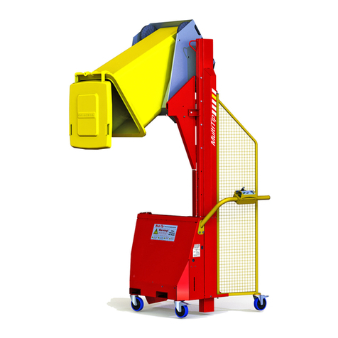
Simpro Multi-Tip User manual
Simpro
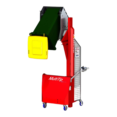
Simpro Multi-Tip 1600 User manual
Simpro
Simpro MegaDumper User manual

Simpro
Simpro QUIKSTAK QS10MM User manual
Simpro
Simpro MegaDumper Series User manual
Simpro
Simpro Dumpmaster User manual
Popular Lifting System manuals by other brands
STINAR
STINAR PS-813B/E Operation & maintenance manual
Upright
Upright POWERED ACCESS TL34 Service manual
ShoreStation
ShoreStation SSV1564M Assembly guide
Genie
Genie Z-30/20N Service manual
WERTHER INTERNATIONAL
WERTHER INTERNATIONAL 263 Original instructions

Lift Products
Lift Products Moto-Cart Jr Service manual

