SimTech SIMCom SIM7100-PCIE Supplement

SIM7100-PCIE_Hardware Design_V1.05
SIMCOM CONFIDENTIAL FILE

Smart Machine Smart Decision
SIM7100-PCIE_Hardware_Design_V1.05 22017-02-24
Document Title SIM7100-PCIE Hardware Design
Version 1.05
Date 2017-02-24
Status Released
Document
Control ID SIM7100-PCIE_Hardware_Design_V1.05
General Notes
SIMCom offers this information as a service to its customers to support the application and engineering efforts
that use the products designed by SIMCom. The information provided is based on the requirements specifically
from the customers. SIMCom has not undertaken any independent search for additional relevant information,
including any information that may be in the customer’s possession. Furthermore, the system validation of the
product designed by SIMCom within a larger electronic system remains the responsibility of the customer or the
customer’s system integrator. All specifications supplied herein are subject to change without notice.
Copyright
This document contains the proprietary technical information which is the property of SIMCom Limited, copying
of this document, giving it to others, the using or communication of the contents thereof are forbidden without the
official authority by SIMCom. Offenders are liable to the payment of the damages. All rights are reserved in the
event of grant of a patent or the registration of a utility model or design. All specifications supplied herein are
subject to change without notice
Copyright © SIMCom Wireless Solutions Co., Ltd. 2017
SIMCOM CONFIDENTIAL FILE

Smart Machine Smart Decision
SIM7100-PCIE_Hardware_Design_V1.05 32017-02-24
Contents
General Notes........................................................................................................................................................... 2
Copyright.................................................................................................................................................................. 2
Contents.................................................................................................................................................................... 3
Table Index............................................................................................................................................................... 5
Figure Index ............................................................................................................................................................. 6
Version History ........................................................................................................................................................ 7
1Introduction....................................................................................................................................................... 8
1.1 Product Outline......................................................................................................................................... 8
1.2 Hardware Interface Overview................................................................................................................... 9
1.3 Hardware Block Diagram....................................................................................................................... 10
1.4 Functional Overview .............................................................................................................................. 10
2Package Information ...................................................................................................................................... 12
2.1 Pin Out Diagram..................................................................................................................................... 12
2.2 PCI Express Mini Card Connector Pin Description ............................................................................... 12
2.3 Package Dimensions............................................................................................................................... 14
3Interface Application ...................................................................................................................................... 15
3.1 Power Supply.......................................................................................................................................... 15
3.2 PERST# .................................................................................................................................................. 15
3.3 W_DISABLE# ....................................................................................................................................... 16
3.4 LED_WWAN#........................................................................................................................................ 16
3.5 WA K E # ................................................................................................................................................... 17
3.6 USB 2.0 .................................................................................................................................................. 18
3.6.1 USB Application Guide....................................................................................................................... 18
USIM Interface..................................................................................................................................................... 19
3.6.2 USIM Application Guide .................................................................................................................... 19
3.7 UART Interface ...................................................................................................................................... 21
3.8 I2C Interface ........................................................................................................................................... 22
3.8.1 I2C Design Guide................................................................................................................................ 22
3.9 PCM/Analog Audio Interface ................................................................................................................. 23
3.9.1 PCM Interface ..................................................................................................................................... 23
3.9.2 PCM timing......................................................................................................................................... 23
3.9.3 PCM Application Guide...................................................................................................................... 25
3.9.4 Analog Audio Interface ....................................................................................................................... 25
4RF Specifications............................................................................................................................................. 27
4.1 GSM/WCDMA/TD-SCDMA/EVDO/LTE RF Specifications ............................................................... 27
4.2 RF Antenna Connector ........................................................................................................................... 30
4.3 GNSS (GPS and GLONASS)................................................................................................................. 33
4.3.1 GNSS Technical specification............................................................................................................. 33
4.3.2 GNSS Operate Mode........................................................................................................................... 33
4.3.3 Application Guide ............................................................................................................................... 34
5Electrical Specifications ................................................................................................................................. 36
5.1 Absolute Maximum Ratings ................................................................................................................... 36
SIMCOM CONFIDENTIAL FILE

Smart Machine Smart Decision
SIM7100-PCIE_Hardware_Design_V1.05 42017-02-24
5.2 Recommended Operating Conditions..................................................................................................... 36
5.3 Operating Mode...................................................................................................................................... 36
5.3.1 Operating Mode .................................................................................................................................. 36
5.3.2 Power saving mode ............................................................................................................................. 37
5.3.3 Sleep mode.......................................................................................................................................... 37
5.3.4 Minimum functionality mode.............................................................................................................. 37
5.4 Current Consumption ............................................................................................................................. 38
5.5 Electro-Static Discharge ......................................................................................................................... 40
6Product label ................................................................................................................................................... 41
Appendix ................................................................................................................................................................ 42
I. Coding Schemes and Maximum Net Data Rates over Air Interface ...................................................... 42
II. Related Documents................................................................................................................................. 44
III. Terms and Abbreviations ........................................................................................................................ 46
IV. Safety Caution ........................................................................................................................................ 48
SIMCOM CONFIDENTIAL FILE

Smart Machine Smart Decision
SIM7100-PCIE_Hardware_Design_V1.05 52017-02-24
Table Index
TABLE 1: SIM7100-PCIE SERIES FREQUENCY BANDS ............................................................................................ 8
TABLE 2: SIM7100-PCIE KEY FEATURES .................................................................................................................. 10
TABLE 3: PCI EXPRESS MINI CARD CONNECTOR PIN DESCRIPTION ............................................................... 12
TABLE 4: RECOMMENDED 3.3V POWER SUPPLY CHARACTERISTICS ............................................................. 15
TABLE 5: PERST# PIN ELECTRONIC CHARACTERISTIC....................................................................................... 15
TABLE 6: W_DISABLE# PIN STATUS ......................................................................................................................... 16
TABLE 7: W_DISABLE# PIN ELECTRICAL CHARACTERISTIC............................................................................. 16
TABLE 8: NETWORK STATUS INDICATION LED STATUS...................................................................................... 16
TABLE 9: USIM ELECTRONIC CHARACTERISTIC IN 1.8V MODE (USIM_VDD =1.8V) .................................... 19
TABLE 10: USIM ELECTRONIC CHARACTERISTIC 3.0V MODE (USIM_VDD =2.95V) ..................................... 19
TABLE 11: UART ELECTRICAL CHARACTERISTIC ................................................................................................ 21
TABLE 12: I2C ELECTRICAL CHARACTERISTIC..................................................................................................... 23
TABLE 13: PCM SPECIFICATION ................................................................................................................................ 23
TABLE 14: PCM DC CHARACTERISTICS .................................................................................................................. 23
TABLE 15: PCM TIMING PARAMETERS .................................................................................................................... 24
TABLE 16: MIC INPUT CHARACTERISTICS ............................................................................................................. 25
TABLE 17: AUDIO OUTPUT CHARACTERISTICS .................................................................................................... 25
TABLE 18: CONDUCTED TRANSMISSION POWER................................................................................................. 27
TABLE 19: OPERATING FREQUENCIES..................................................................................................................... 27
TABLE 20: E-UTRA OPERATING BANDS................................................................................................................... 28
TABLE 21: CONDUCTED RECEIVE SENSITIVITY ................................................................................................... 29
TABLE 22: REFERENCE SENSITIVITY (QPSK)......................................................................................................... 29
TABLE 23: RECOMMENDED PASSIVE ANTENNA CHARACTERISTICS.............................................................. 30
TABLE 24: RECOMMENDED ACTIVE ANTENNA CHARACTERISTICS ............................................................... 30
TABLE 25: ABSOLUTE MAXIMUM RATINGS........................................................................................................... 36
TABLE 26: OPERATING CONDITIONS ....................................................................................................................... 36
TABLE 27: OPERATING MODE.................................................................................................................................... 36
TABLE 28: CURRENT CONSUMPTION (VCC =3.2V~3.6V)...................................................................................... 38
TABLE 29: ESD CHARACTERISTICS (TEMPERATURE: 25℃, HUMIDITY: 45 %)................................................ 40
TABLE 30: CODING SCHEMES AND MAXIMUM NET DATA RATES OVER AIR INTERFACE .......................... 42
TABLE 31: RELATED DOCUMENTS ........................................................................................................................... 44
TABLE 32: TERMS AND ABBREVIATIONS................................................................................................................ 46
TABLE 33: SAFETY CAUTION..................................................................................................................................... 48
SIMCOM CONFIDENTIAL FILE

Smart Machine Smart Decision
SIM7100-PCIE_Hardware_Design_V1.05 62017-02-24
Figure Index
FIGURE 1: SIM7100-PCIE BLOCK DIAGRAM ........................................................................................................... 10
FIGURE 2: SIM7100-PCIE PIN OUT DIAGRAM ......................................................................................................... 12
FIGURE 3: DIMENSIONS OF SIM7100-PCIE (UNIT: MM) ........................................................................................ 14
FIGURE 4: PERST# REFERENCE CIRCUIT ................................................................................................................ 15
FIGURE 5: W_DISABLE# REFERENCE CIRCUIT...................................................................................................... 16
FIGURE 6: LED_WWAN# REFERENCE CIRCUIT...................................................................................................... 17
FIGURE 7: WAKE# BEHAVIOUR ................................................................................................................................. 17
FIGURE 8: WAKE# BEHAVIOUR AS A CALLER........................................................................................................ 17
FIGURE 9: WAKE# REFERENCE CIRCUIT................................................................................................................. 18
FIGURE 10: USB REFERENCE CIRCUIT .................................................................................................................... 18
FIGURE 11: USIM INTERFACE REFERENCE CIRCUIT WITH DETECTION FUNCTION .................................... 20
FIGURE 12: USIM INTERFACE REFERENCE CIRCUIT............................................................................................ 20
FIGURE 13: UART FULL MODEM ............................................................................................................................... 21
FIGURE 14: UART NULL MODEM............................................................................................................................... 21
FIGURE 15: REFERENCE CIRCUIT OF LEVEL SHIFT.............................................................................................. 22
FIGURE 16: I2C REFERENCE CIRCUIT ...................................................................................................................... 22
FIGURE 17: PCM_SYNC TIMING ................................................................................................................................ 24
FIGURE 18: EXT CODEC TO MODULE TIMING ....................................................................................................... 24
FIGURE 19: MODULE TO EXT CODEC TIMING ....................................................................................................... 24
FIGURE 20: AUDIO CODEC REFERENCE CIRCUIT ................................................................................................. 25
FIGURE 21: RECEIVER INTERFACE CONFIGURATION.......................................................................................... 26
FIGURE 22: MICROPHONE INTERFACE CONFIGURATION................................................................................... 26
FIGURE 23: ANTENNA MATCHING CIRCUIT (MAIN_ANT)................................................................................... 31
FIGURE 24: ANTENNA MATCHING CIRCUIT (AUX_ANT)..................................................................................... 32
FIGURE 25: U.FL-R-SMT............................................................................................................................................... 32
FIGURE 26: U.FL SERIES RF ADAPTER CABLE ....................................................................................................... 33
FIGURE 27: ACTIVE ANTENNA CIRCUIT.................................................................................................................. 35
FIGURE 28: PASSIVE ANTENNA CIRCUIT (DEFAULT) ........................................................................................... 35
FIGURE 29: THE LABLE OF SIM7100-PCIE ............................................................................................................... 41
FIGURE 30: THE LABLE OF SIM7100-PCIEA ............................................................................................................ 41
SIMCOM CONFIDENTIAL FILE

Smart Machine Smart Decision
SIM7100-PCIE_Hardware_Design_V1.05 72017-02-24
Version History
Date
Version
Description of change
Author
2015-04-07 1.01 Origin Ye Haibing
Xing Lei
2016-03-24 1.02 Update the frequency band information of SIM7100CE,
SIM7100V Ma Honggang
2016-09-28 1.03
Update the date of current consumption
Add the label picture of SIM7100-PCIEA
Renew the codec from WM8960 to NAU8810
Zhang Xiaojun
2016-11-09 1.04 Update the Figure 11 and the Figure 12 Zhang Xiaojun
2017-02-24 1.05
Delete LTE-FDD B13 information;
Add peak current consumption information;
Add the UIM hot-swap AT commands description;
Add BAND 19 information
;
Ma Honggang
SIMCOM CONFIDENTIAL FILE

Smart Machine Smart Decision
SIM7100-PCIE_Hardware_Design_V1.05 82017-02-24
1Introduction
This document describes the electronic specifications, RF specifications, interfaces, mechanical characteristics
and testing results of the SIMCom SIM7100-PCIE modules. With the help of this document and other related
software application notes/user guides, users can understand and use SIM7100-PCIE modules to design and
develop applications quickly.
1.1 Product Outline
Aimed at global market, the SIM7100-PCIE modules support 5 air-interface standards including GSM,
TD-SCDMA, CDMA, WCDMA and LTE. Users can choose the module according to the wireless network
configuration. The supported radio frequency bands are described in the following table.
Table 1: SIM7100-PCIE Series Frequency Bands
Standard Frequency
SIM7100x-PCIE(A)*
x=”C” x=”CE” x=”E” x=”JE” x=”JC” x=”V” x=”A”
GSM
GSM 850MHz
EGSM 900MHz
DCS
1800MHz
PCS
1900MHz
CDMA2000/
EVDO BC0
WCDMA
BAND5
BAND6
BAND8
BAND2
BAND1
TD-SCDMA
TD-SCDMA 1.9G
TD-SCDMA 2G
LT E -FDD
LT E -FDD B1
LT E -FDD B2
LT E -FDD B3
LT E -FDD B4
LT E -FDD B5
LT E -FDD B7
LT E -FDD B8
LT E -FDD B17
LT E -FDD B18
LT E -FDD B19
LT E -FDD B20
SIMCOM CONFIDENTIAL FILE

Smart Machine Smart Decision
SIM7100-PCIE_Hardware_Design_V1.05 92017-02-24
LT E -TDD
LTE TDD B38
LTE TDD B39
LTE TDD B40
LT E TDD B41
GNSS GPS
GLONASS
*Note: If Analog audio is needed, please consult our sales staff, for more information .
1.2 Hardware Interface Overview
SIM7100-PCIE provides various hardware interfaces via Mini PCI Express card connector.
●Power Supply
●PERST#
●W_DISABLE#
●LED_WWAN#
●WA K E #
●USB Interface
●USIM Interface
●UART Interface
●I2C Interface
●PCM Interface
●Analog Audio Interface
SIMCOM CONFIDENTIAL FILE

Smart Machine Smart Decision
SIM7100-PCIE_Hardware_Design_V1.05 10 2017-02-24
1.3 Hardware Block Diagram
The following figure is SIM7100-PCIE hardware block diagram.
GSM/WCDMA
/TD/LTE
RF FEM
RF GSM
WCDMA/TD/LTE
PA
RF
Transceiver
Processor
XO
19.2MHz
RF
TDSCDMA/LTE-
TDD PA
GNSS
RF
Main Antenna GNSS Antenna
Power
Management
Qualcomm
Chip
WCDMA
/LTE
RF FEM
Aux Antenna
DCDC
52 PIN Mini PCI-E Interface
3.3V
LED_WWAN#
PCM
USB
USIM
WAKE#
W_DISABLE#
PERST#
Codec
I2C MIC_N
MIC_P
EAR_P
EAR_N
UART
MCP
DDR(1GB)
NAND(2GB)
SIM CARD
I2C
Figure 1: SIM7100-PCIE Block Diagram
1.4 Functional Overview
Table 2: SIM7100-PCIE Key Features
Feature
Implementation
Power supply
Single supply voltage 3.2V~3.6V
Radio frequency bands
Please refer to the table 1
Transmitting power
GSM/GPRS:
Class 4 (2W): GSM850、EGSM900
Class 1 (1W): DCS1800、PCS1900
EDGE:
Class E2 (0.5W): GSM850、EGSM900
Class E1 (0.4W): DCS1800、PCS1900
UMTS:
Class 3 (0.25W): WCDMA,
Class 3 (0.25W): CDMA2000
Class 2 (0.25W): TD-SCDMA
LTE:
Class 3 (0.2W): LTE
Data Transmission
Throughput
GPRS multi-slot class 12
EDGE multi-slot class 12
UMTS R99 speed: 384 kbps DL/UL
SIMCOM CONFIDENTIAL FILE

Smart Machine Smart Decision
SIM7100-PCIE_Hardware_Design_V1.05 11 2017-02-24
HSPA+: 5.76 Mbps(UL), 42 Mbps(DL)
TD-HSDPA/HSUPA: 2.2 Mbps(UL), 2.8 Mbps(DL)
CDMA EVDO:Rev-0,Rev-A, Rev-B
LTE Category 3 - 100 Mbps (DL)
LTE Category 3 - 50 Mbps (UL)
Antenna
GSM/UMTS/LTE main antenna.
UMTS/LTE auxiliary antenna.
GPS/GLONASS antenna.
GNSS
GNSS engine (GPS and GLONASS)
Protocol: NMEA
GPS supports MS/UE-based, MS/UE-assisted and hybrid modes
with AFLT (CDMA), NMR (GSM), and MRL(UMTS, WCDMA,
LTE), standalone and network-aware modes
GLONASS supports standalone mode
SMS
MT, MO, CB, Text and PDU mode
SMS storage: USIM card or ME(default)
Transmission of SMS alternatively over CSD or GPRS.
USIM interface Support identity card: 1.8V/ 3V
USIM application toolkit
Support SAT class 3, GSM 11.14 Release 98
Support USAT
Phonebook management
Support phonebook types: SM, FD, LD, RC, ON, MC
Audio feature
Support PCM interface. Only support PCM master mode and short
frame sync, 16-bit linear data formats. Available only when audio
codec chip is not mounted on PCIE board.
One analog signal output with 32Ω load resistance,50mW output
power, and one analog input. Available only when audio codec
chip is mounted on PCIE board.
UART interface
A full modem serial port by default
Baud rate: 300bps to 4Mbps(default:115200bps)
Autobauding baud rate: 1200 bps to 115200bps
Can be used as the AT commands or data stream channel.
Support RTS/CTS hardware handshake and software ON/OFF
flow control
Multiplex ability according to GSM 07.10 Multiplexer Protocol.
USB USB 2.0 specification-compliant as a peripheral
Firmware upgrade
Firmware upgrade over USB interface
FOTA
Physical characteristics
Size: 50.80*31*5.35mm
Weight:less than 12g
Temperature range
Normal operation temperature: -30°C to +80°C
Extended operation temperature: -40°C to +85°C*
Storage temperature -45°C to +90°C
*Note: Module is able to make and receive voice calls, data calls, SMS and make GPRS/WCDMA/HSPA+/LTE
traffic in -40℃~+85℃. The performance will reduce slightly from the 3GPP specifications if the temperature
is outside of the normal operating temperature and still within the extreme operating temperature.
SIMCOM CONFIDENTIAL FILE

Smart Machine Smart Decision
SIM7100-PCIE_Hardware_Design_V1.05 12 2017-02-24
2Package Information
2.1 Pin Out Diagram
Figure 2: SIM7100-PCIE Pin Out Diagram
2.2 PCI Express Mini Card Connector Pin Description
Table 3: PCI Express Mini Card Connector Pin Description
Pin name Pin number I/O Description Comment
Power supply
VCC 2,24,39,41,52 I 3.3V Power supply for module -
GND
4,9,15,18,21,
26,27,29,34,3
5,37,40,43,50
Ground -
Reset
PERST# 22 I Reset input (Active low) If unused, keep
open.
USB 2.0
USB_DP 38 I/O USB 2.0 high speed port for data transfer, voice
call, debug and FW download, etc.
If unused, keep
open.
USB_DN 36
SIMCOM CONFIDENTIAL FILE

Smart Machine Smart Decision
SIM7100-PCIE_Hardware_Design_V1.05 13 2017-02-24
USIM card interface
USIM_VDD 8 O
Power output for USIM card, its output Voltage
depends on USIM card type automatically. Its
output current is up to 50mA.
-
USIM_D ATA 10 I/O
USIM Card data I/O, which has been pulled up
via a 20KR resistor to USIM_VDD internally.
Do not pull it up or down externally.
-
USIM_CLK 12 O USIM clock -
USIM_RST 14 O
USIM Reset
-
USIM_DET 16 I
USIM card detect
-
PCM interface
PCM_CLK 45 O PCM data bit clock. If these pins are
unused, keep open.
The PCM interface
can not be used, if
Audio Codec chip is
mounted on PCIE
board.
PCM_OUT 47 O PCM data output
PCM_IN 49 I PCM data input
PCM_SYNC 51 O PCM data frame sync signal.
UART interface
UART_CTS 11 I Clear to Send
If unused, keep open
UART_RTS 13 O Request to send
UART_RXD 17 I Receive Data
UART_TXD
19
O
Transmit Data
UART_RI 44 O Ring Indicator
UART_DTR 46 I DTE get ready
I2C interface
SCL 30 O I2C clock output If unused, keep open
SDA 32 I/O I2C data input/output
others
WA K E # /M I C P 1
I/O Default: Wake up host
Optional:MIC positive input
If unused, keep
open.
If Analog audio is
available, wake up
function is invalid.
If Analog audio is
needed,please
consult our sales
staff, for more
information .
MICN 3
I Default:NC
Optional: MIC negative input
EARP 5 O
Default: NC
Optional: Receiver positive output
EARN 7 O Default: NC
SIMCOM CONFIDENTIAL FILE

Smart Machine Smart Decision
SIM7100-PCIE_Hardware_Design_V1.05 14 2017-02-24
Optional: Receiver negative output
W_DISABLE# 20 I RF Control Input If unused, keep
open.
LED_WWAN# 42 O Network Status Indication output If unused, keep
open.
NC 6,23,25,28,31
,33,48
-- No connection Keep open
2.3 Package Dimensions
Figure 3: Dimensions of SIM7100-PCIE (Unit: mm)
SIMCOM CONFIDENTIAL FILE

Smart Machine Smart Decision
SIM7100-PCIE_Hardware_Design_V1.05 15 2017-02-24
3Interface Application
3.1 Power Supply
The recommended power supply voltage of SIM7100-PCIE is 3.3V.
Table 4: Recommended 3.3V Power Supply Characteristics
Symbol Parameter Min Type Max Unit
Vo Power supply voltage 3.2 3.3 3.6 V
Io Supply current capability - 2000 - mA
3.2 PERST#
SIM7100-PCIE can be reset by pulling the PERST# pin down to ground.
The PERST# pin has been pulled up with a 40KΩ resistor to 1.8V internally, so there is no need to pull it up
externally. It is strongly recommended to put a 100nF capacitor and an ESD protection diode close to the RESET
pin. Please refer to the following figure for the recommended reference circuit.
4.7K
47K
Reset Impulse
PERST#
Reset
Logic
40K
1.8V
MODULE
100nF
T
reset
Figure 4: PERST# Reference Circuit
Table 5: PERST# Pin Electronic Characteristic
Symbol
Description
Min.
Typ.
Max.
Unit
Treset The active low level time impulse on
PERST# pin to reset module 50 100 500 ms
VIH Input high level voltage 1.17 1.8 3.6 V
VIL Input low level voltage -0.3 0 0.3 V
SIMCOM CONFIDENTIAL FILE

Smart Machine Smart Decision
SIM7100-PCIE_Hardware_Design_V1.05 16 2017-02-24
3.3 W_DISABLE#
The W_DISABLE# pin can be used to control SIM7100-PCIE to enter or exit the Flight mode. In Flight mode,
the RF circuit is closed to prevent interference with other equipments and minimize current consumption.
Table 6: W_DISABLE# Pin Status
W_DISABLE# status
Module operation
Input Low Level
Flight Mode: RF is closed.
Input High Level
Normal Mode: RF is working.
MODULE
47K
W_DISABLE
GPIO
4.7K
4.7K
Switch
1.8V
1.8V
Figure 5: W_DISABLE# Reference Circuit
Table 7: W_DISABLE# Pin Electrical Characteristic
Symbol
Parameter
Min
Type
Max
Unit
V IH
High-level input voltage
1.17
1.8
3.6
V
V
IL
Low-level input voltage -0.3 0 0.3 V
3.4 LED_WWAN#
The LED_WWAN# pin can be used to drive a network status indication LED by default. Its status is listed in
the following table.
Table 8: Network Status Indication LED Status
LED Status
Module Status
On
Searching Network/Call Connect
200ms On, 200ms Off
Data Transmit
800ms On, 800ms Off
Registered network
Off
Power off / Sleep
Reference circuit is recommended in the following figure:
SIMCOM CONFIDENTIAL FILE

Smart Machine Smart Decision
SIM7100-PCIE_Hardware_Design_V1.05 17 2017-02-24
MODULE
VCC
R
LED_WWAN#
GND
GPIO
Figure 6: LED_WWAN# Reference Circuit
3.5 WA K E #
The WAKE# pin can be used as an interrupt signal to host. Normally it will keep high logic level until certain
condition such as receiving SMS, voice call (CSD, video) or URC reporting, then WAKE# will change to low
logic level to inform the master (client PC). It will stay low until the master clears the interrupt event with AT
command.
Idle
HIGH
LOW
Receiving SMS , incoming
voice (CSD, video) call and
any URC report.
AT+CFGRI=1
WAKE# Clear by AT+CRIRS
Idle
HIGH
LOW
Receiving SMS , incoming
voice (CSD, video) call only.
AT+CFGRI=0
WAKE# Clear by AT+CRIRS
Figure 7: WAKE# behaviour
However, if the module is used as caller, the WAKE# will remain high. Please refer to the following figure.
HIGH
LOW
Idle Ring Establish
the call
Hang up
the call
Idle
WAKE#
Figure 8: WA K E # behaviour as a caller
SIMCOM CONFIDENTIAL FILE

Smart Machine Smart Decision
SIM7100-PCIE_Hardware_Design_V1.05 18 2017-02-24
WAKE# Reference circuit is recommended in the following figure:
MODULE
GPIO
VCC
Rpull-up
WAKE#
GND
HOST
Interrupt input
VDD
_1V8
Figure 9: WAKE# Reference Circuit
Note: If Analog audio is available, wake up function is invalid. Please consult our sales staff for more
information.
3.6 USB 2.0
SIM7100-PCIE is compliant with USB 2.0 specification. It supports full-speed and high- speed when acting as a
peripheral device.
3.6.1 USB Application Guide
SIM7100-PCIE can be used as a USB device. SIM7100-PCIE supports the USB suspend and resume
mechanism which can reduce power consumption. If there is no data transmission on the USB bus,
SIM7100-PCIE will enter suspend mode automatically, and will be resumed by some events such as voice call
or receiving SMS, etc.
USB_DN
USB_DP
MODULE HOST
USB port
USB port D-
D+
GND
TVS
TVS
GND
Figure 10: USB Reference Circuit
Because of the high bit rate on USB bus, please pay more attention to the influence of the junction capacitance
of the ESD component on USB data lines. Typically, the capacitance should be less than 1pF. It is recommended
to use an ESD protection component such as ESD9L5.0ST5G provided by On Semiconductor
SIMCOM CONFIDENTIAL FILE

Smart Machine Smart Decision
SIM7100-PCIE_Hardware_Design_V1.05 19 2017-02-24
(www.onsemi.com ).
Note
:
1. The USB_DN and USB_DP nets must be traced by 90Ohm+/-10% differential impedance.
2. The USB VBUS of the module is connected to VBAT internally,so there is no need to connect externally.
3. The SIM7100-PCIE has two kinds of interface (UART and USB) to connect to host CPU. For example,
on windows XP operating system, USB interface is mapped to 6 virtual ports: “SIMTECH HS-USB
Modem 9001”, “SIMTECH HS-USB AT port 9001”, “SIMTECH HS-USB Audio 9001”, “SIMTECH
HS-USB Diagnostics 9001”, “SIMTECH HS-USB NMEA 9001” and “SIMTECH Wireless HS-USB
Ethernet Adapter 9001”.
USIM Interface
USIM interface complies with the GSM Phase 1 specification and the new GSM Phase 2+ specification for FAST
64 kbps SIM card.Both 1.8V and 3.0V SIM card are supported.USIM interface is powered from an internal
regulator in the module.
Table 9: USIM Electronic characteristic in 1.8V mode (USIM_VDD =1.8V)
Symbol Parameter Min. Typ. Max. Unit
USIM_VDD LDO power output voltage 1.75 1.8 1.95 V
VIH High-level input voltage 0.65·USIM_V
DD - USIM_VDD
+0.3 V
VIL Low-level input voltage -0.3 0 0.35·USIM_V
DD
V
VOH High-level output voltage USIM_VDD
-0.45 - USIM_VDD V
VOL Low-level output voltage 0 0 0.45 V
Table 10: USIM Electronic characteristic 3.0V mode (USIM_VDD =2.95V)
Symbol Parameter Min. Typ. Max. Unit
USIM_VDD LDO power output voltage 2.75 2.95 3.05 V
VIH High-level input voltage 0.65*USIM_V
DD - USIM_VDD
+0.3 V
VIL Low-level input voltage -0.3 0 0.25·USIM_V
DD V
VOH High-level output voltage USIM_VDD
-0.45 - USIM_VDD V
VOL Low-level output voltage 0 0 0.45 V
3.6.2 USIM Application Guide
It is recommended to use an ESD protection component such as ST (www.st.com ) ESDA6V1W5. Note that
the SIM peripheral circuit should be close to the SIM card socket. For more details of AT commands about
USIM, please refer to document [1].
SIMCOM CONFIDENTIAL FILE

Smart Machine Smart Decision
SIM7100-PCIE_Hardware_Design_V1.05 20 2017-02-24
The SIM_DET pin is used for detection of the SIM card hot plug. User can select the 8-pin SIM card holder
to implement SIM card detection function.
MODULE
PRESENCE
100nF
SCGD1B0201
SIM CARD
22pF
VCC GND
RST VPP
CLK I/O
GND
VDD_EXT
SIM_VDD
SIM_RST
SIM_CLK
SIM_DATA
4.7K
ESDA6V1
SIM_DET
22Ω
22Ω
22Ω
22pF 22pF
Figure 11: USIM interface reference circuit with detection function
For the normal open kind SIM socket, customer should set AT+UIMHOTSWAPLEVEL=0, and for the
normal close kind SIM socket, customer should set AT+UIMHOTSWAPLEVEL=1.
If the SIM card detection function is not used, user can keep the SIM_DET pin open. The reference circuit of
6-pin SIM card holder is illustrated in the following figure.
MODULE
SIM_VDD
SIM_CLK
SIM_DATA
SIM_RST VCC GND
RST VPP
CLK I/O
22Ω
100nF
C707 10M006 512
SIM CARD
22Ω
22Ω
22pF22pF22pF ESDA6V1
Figure 12: USIM interface reference circuit
Note: USIM_DATA has been pulled up with a 20KΩ resistor to USIM_VDD in module. A 100nF capacitor
on USIM_VDD is used to reduce interference.
SIMCOM CONFIDENTIAL FILE
Other manuals for SIMCom SIM7100-PCIE
1
Table of contents
Other SimTech Control Unit manuals
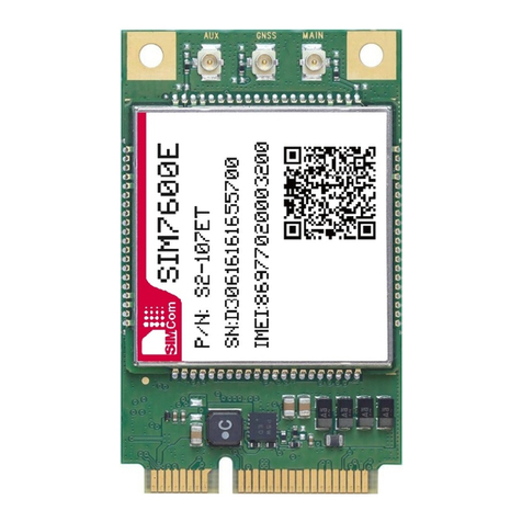
SimTech
SimTech SIMCom SIM7600E-PCIE Supplement
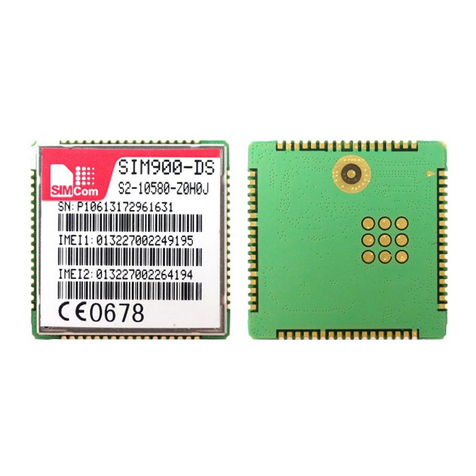
SimTech
SimTech SIMCom SIM900-DS Supplement
SimTech
SimTech SimCom SIM5320JE-TE Supplement
SimTech
SimTech SIMCom SIM6216C Supplement
SimTech
SimTech SIMCom SIM5360 Supplement
SimTech
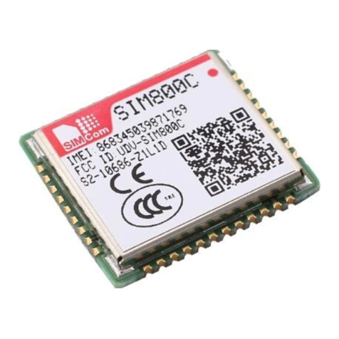
SimTech SIMCom SIM800C Supplement
SimTech
SimTech SimCom SIM7100 Supplement
SimTech
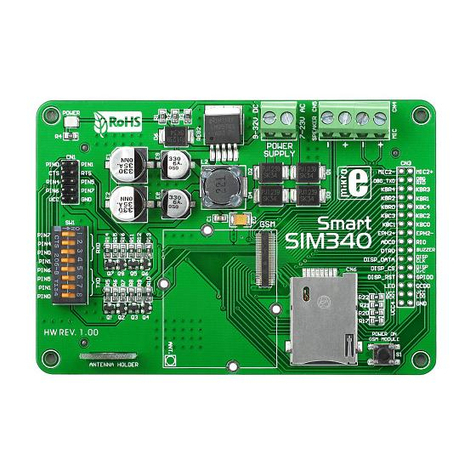
SimTech SimCom SIM340 Supplement
SimTech
SimTech SIMCom SIM7100-PCIE Supplement
SimTech
SimTech SimCom SIM800 Series Supplement
