Sincro PMG140K Series User manual

S
ERIE PMG140K
Manuale di uso e manutenzione
Use and Maintenance manual
166534
REV00
03/2019
166534
REV00
03/201
9

2
INDICE
1 INFORMAZIONI SULLA SICUREZZA.....................3
1.1 Fonti di possibile pericolo..........................................4
1.1.1 Pericoli meccanici......................................................4
1.1.2 Pericoli elettrici...........................................................4
2 USO PREVISTO.......................................................5
3 ISTRUZIONI PER L’INSTALLAZIONE,
L’IMPIEGO E LO STOCCAGGIO ............................6
3.1 Informazioni generali.................................................6
3.2 Movimentazione e giacenza a magazzino...............7
3.3 Modalità di accoppiamento.......................................7
3.4 Collegamenti e terminali...........................................11
3.5 Veri!ca della resistenza di isolamento ....................12
3.6 Messa in marcia .......................................................12
4 PRINCIPIO DI FUNZIONAMENTO ........................12
5 ASSISTENZA E MANUTENZIONE........................13
5.1 Cuscinetti ................................................................ .13
5.2 Risoluzione dei problemi........................................ .14
6 DEMOLIZIONE E SMALTIMENTO....................... .16
7 CONNESSIONI...................................................... .16
7.1 Collegamento cavi di potenza ............................... .16
ALLEGATI
RICAMBI E ASSISTENZA..................................... .18
GARANZIA............................................................. .20
Dichiarazione di incorporazione ............................ .23
CONTENTS
1 SAFETY INFORMATION..........................................3
1.1 Sources of potential hazard......................................4
1.1.1 Mechanical hazard....................................................4
1.1.2 Electrical hazard........................................................4
2 USE............................................................................5
3 INSTRUCTIONS FOR INSTALLATION
AND STOCKING.......................................................6
3.1 General information...................................................6
3.2 Handling, lifting amd storage ....................................7
3.3 Coupling con•gurations ............................................7
3.4 Cabling and terminals..............................................11
3.5 Insulation resistance check...........................................12
3.6 Initial start-up............................................................12
4 OPERATING PRINCIPLE........................................12
5 MAINTENANCE AND SERVICE .............................13
5.1 Bearings.................................................................. 13
5.2 Troubleshooting...................................................... 15
6 DISMANTLING....................................................... 16
7 TERMINAL BOARD CONNECTION .................... .16
7.1 Power connections...................................................16
ATTACHMENTS
SPARE PARTS & AFTERSALES.......................... 18
WARRANTY........................................................... 20
Declaration of Incorporation................................... 23
3
1 INFORMAZIONI SULLA SICUREZZA
Il “Manuale Uso e Manutenzione” accluso al generatore
fornisce importanti indicazioni riguardanti la sicurezza,
l’installazione, l’uso e la manutenzione.
Questo manuale di istruzioni è stato redatto sulla base
delle indicazioni fornite dalla Direttiva europea 2006/42/
CE (“Direttiva Macchine”) e dalla norma IEC 82079-1
Attenersi scrupolosamente a quanto riportato nel ma-
nuale, che ha lo scopo di indicare le corrette condizioni
di installazione e manutenzione, al !ne di prevenire
eventuali malfunzionamenti del generatore ed evitare
situazioni di pericolo per l’utente.
Questo prodotto è stato progettato e costruito esclu-
sivamente per l’utilizzo indicato in questa documen-
tazione. Usi non indicati in questa documentazione
potrebbero essere fonte di danni al prodotto e fonte di
pericolo.
Sono stati riportati inoltre tutti i suggerimenti informativi
derivanti da esperienze applicative, necessari per ga-
rantire l’uso corretto e sicuro del generatore elettrico.
I generatori elettrici della serie PMG140K sono confor-
mi alle seguenti direttive:
- Direttiva europea 2006/42/CE (“Direttiva Macchi-
ne”);
- Direttiva europea 2014/35/CE (“Direttiva Bassa
tensione”);
- Direttiva europea 2014/30/CE (“Direttiva sulla
compatibilità elettromagnetica”).
I generatori della serie PMG140K sono stati progettati
seguendo le seguenti norme internazionali IEC 60034
(“Macchine elettriche rotanti”). La veri!ca della compa-
tibilità elettromagnetica è stata condotta in base alle
seguenti norme: EN 61000-6-2 e EN 61000-6-4.
In questo manuale vengono utilizzati alcuni simboli e con-
venzioni che hanno un signi!cato preciso.
ATTENZIONE!
Il simbolo si riferisce a situazioni di rischio
o a procedure pericolose che potrebbero
essere causa di danni al prodotto o di
lesioni alla persona.
AVVERTENZA!
Il simbolo segnala situazioni di rischio
o procedure pericolose che potrebbero
essere causa di gravi lesioni alla persona
o di decesso.
PERICOLO!
Il simbolo segnala situazioni di rischio o
procedure pericolose che causano gravi
lesioni alla persona o decesso.
1 SAFETY INFORMATION
The “User and Maintenance Manual” included with
the generator provides important indications regarding
safety, installation, use and maintenance.
This instruction manual has been compiled in accord-
ance with information supplied on the matter by the
2006/42/EC Regulation (“Machine Directive”) and by
the IEC 82079-1.
Strictly observe the instructions given in the “User and
Maintenance Manual” that is provided to indicate the
correct conditions for installation, use and mainte-
nance, in order to prevent malfunctions in the generator
and avoid hazardous situations for the user.
This product has been designed and constructed solely
for the application indicated in this manual. Any use
not speci•ed in this manual may cause damage to the
product and become a source of hazard.
All information suggestions deriving from application
experience have been included, as these are neces-
sary to guarantee the correct, safe use of electric gen-
erator.
The PMG140K series generators comply with following
directives:
-European Directive 2006/42/EC (“Machine Direc-
tive”);
-European Directive 2014/35/EC (“Low Voltage
Directive”);
-European Directive 2014/30/EC (“Electromagnetic
Compatibility Directive”).
The PMG140K series generators were designed to
meet the following international standards: IEC 60034
(“Rotating Electrical Machines”). The following stand-
ards were used to evaluate the electro-magnetic com-
patibility: EN 61000-6-2 and EN 61000-6-4.
This manual uses various symbols and terms that have a
precise meaning. These are clearly de•ned below.
CAUTION!
This symbol signals risk conditions or
hazardous procedures that could cause
damage to the product or injury to
persons.
WARNING!
This symbol signals risk conditions or
hazardous procedures that could cause
severe injury or death.
DANGER!
This symbol signals risk conditions or
hazardous procedures that will cause
severe injury or death.
4
1.1 Fonti di possibile pericolo
Ci sono una varietà di fonti di potenziali pericoli che
possono causare la morte o gravi lesioni. Questi pe-
ricoli sono presenti durante l’installazione, il funziona-
mento, o di ispezione e manutenzione.
1.1.1 PERICOLI MECCANICI
ATTENZIONE!
Non toccare mai il rotore.
Mai cercare di fermare il rotore a mano.
Evitare che qualsiasi oggetto entri nel
rotore.
Mai cercare di fermare il rotore lancian-
do qualsiasi oggetto su di esso.
ATTENZIONE!
Indossare indumenti di sicurezza adeg-
uate e rendere l’area di lavoro il più pos-
sibile ordinata e sicura.
Utilizzare caschi di sicurezza, guanti, ecc.
Molta attenzione deve essere prestata alla resistenza ed
integrità del montaggio. Utilizzare mezzi idonei per il solle-
vamento e la movimentazione del generatore (Se presen-
ti, utilizzare tutti i golfari di sollevamento). La caduta di og-
getti è potenzialmente fatale. Non sottostare sotto i carichi
sospesi o sotto i montanti. Assicurarsi che gli astanti siano
tenuti al di fuori del raggio di caduta di eventuali oggetti.
Assicurarsi che eventuali oggetti o utensili sospesi siano
messi in sicurezza.
ATTENZIONE!
Fissare eventuali oggetti che potrebbero
cadere. Non sostare sotto carichi sosp-
esi e l’area di lavoro, indossare il casco
di sicurezza. Utilizzare solo sistemi di
montaggio adeguatamente progettati.
1.1.2 PERICOLI ELETTRICI
PERICOLO!
Non toccare i terminali dei "li, se il
generatore è in rotazione. Non toccare
i terminali dei "li, se il generatore non
è completamente scollegato dalla
linea / ponte raddrizzatore trifase.
PERICOLO!
Per il collegamento a massa fare riferi-
mento alle corrispondenti norme locali in
materia. Collegamenti a massa o di pro-
tezione eseguiti in modo errato possono
portare a lesioni o al decesso.
1.1 Sources of potential hazard
There are a variety of sources of potential hazards
which can result in death or serious injury. These dan-
gers exist during installation, operation, or inspection
and maintenance.
1.1.1 MECHANICAL HAZARD
CAUTION!
Never touch the rotor in motion.
Never try to stop the rotor by hand.
Avoid any objects entering the rotor.
Never try to stop the rotor by throwing
any object into it.
CAUTION!
Wear appropriate safety equipment
and make the general working area as
a tidy and safe as possible.
Use safety helmets, gloves, etc.
Very careful attention must be given to the strength and
integrity of the mounting. Use appropriate tools to lift and
move the generator (For lifting use all eyebolts that the
generator is equipped with). Falling objects are potentially
fatal. Do not step underneath hanging loads or folding/
tilted masts. Make sure that onlookers are kept back be-
yond the collapse radius of any masts. Ensure that any
suspended objects or tools are secured.
CAUTION!
Secure any objects that might fall.
Do not go underneath hanging loads
and the working area; wear safety hel-
mets. Only use adequately designed
mounting systems.
1.1.2 ELECTRICAL HAZARD
DANGER!
Don’t touch the wire terminals if the
generator is rotating.
Don’t touch the wire terminals if
the generator is not completely
disconnected to the line/three phase
full bridge.
DANGER!
Follow local regulations on earthing
for the ground connection. An
inef!cient earth connection can
cause injury or death.

5
ATTENZIONE!
Le connessioni elettriche devono
essere eseguite da personale
quali"cato. Connessioni eseguite
in modo errato possono causare
danni a persone e danneggiare il
generatore.
2 USO PREVISTO
I generatori elettrici della serie PMG140K sono genera-
tori sincroni a magneti permanent.
Essendo classi!cati dalla direttiva europea 2006/42/
CE, come “quasi-macchine”, non devono essere messi
in servizio !nché la macchina !nale, alla quale devono
essere incorporati non è stata dichiarata conforme alle
disposizioni della stessa direttiva.
I generatori elettrici della serie PMG140K sono macchi-
ne del tipo chiuso.
Per le comunicazioni con Soga, si prega di citare sempre il
tipo ed il codice del generatore, rilevabili sulla targa come
riportato sotto. Nel caso, inoltre, in cui vi siano malfunzio-
namenti o altri tipi di guasto nella macchina e si rendes-
se necessario interpellare il nostro Servizio Assistenza,
si prega di menzionare anche il numero di serie (SN) ed
il codice. Sulla targhetta sono riportati i seguenti dati
relativi all’uscita in DC: potenza, tensione, corrente e
velocità nominali.
CAUTION!
Only quali•ed personel can make
the electrical connections. Wrong
connections can cause injury to
the persons and can damage the
generator.
2 USE
The PMG140K generator series are permanent magnet
synchronous generators.
It is also declared that generators, identi•ed by the
european directive 2006/42/EC as “partly completed
machinery”, must not be put into service until the •nal
machine, in which they are incorporated, has been
declared to comply with the prescriptions of the same
directive 2006/42/EC.
The PMG140K generator series are machine of the
closed type.
When contacting Soga, always report the generator type
and code, found on the nameplate. What’s more, in the
event of malfunction or any other kind of machine fault that
should require our Aftersales Service, please specify the
serial number (SN) and code.
On the nameplate are shown the following data con-
cerning the DC output: nominal power, voltage, current
and speed.
TIPO ALTERNATORE/ ALTERNATOR TYPE
CODICE ALTERNATORE/ ALTERNATOR CODE
N° SERIALE / SERIAL NUMBER
Fig. 1

6
Se non diversamente speci!cato i modelli sono proget-
tati per temperature ambientali comprese tra -15°C e
+50°C e per altitudini non superiori a 1000m s.l.m.
Controllare la targa e confrontarla con le speci!che
dell’ordine al momento della consegna onde accertare
eventuali errori di spedizione o di con!gurazione. Per
temperature maggiori di +50°C e per ambienti con tem-
perature costantemente inferiori ai -15°C, per sovrac-
carichi, servizi di durata limitata o per servizi intermit-
tenti è consigliabile consultare di volta in volta i nostri
Uf!ci Tecnici.
3 ISTRUZIONI PER L’INSTALLAZIONE,
L’IMPIEGO E LO STOCCAGGIO
Tutti i lavori di installazione, montaggio, messa in ser-
vizio, manutenzione, devono essere eseguiti da per-
sonale quali!cato e controllati dal personale tecnico
responsabile.
Il generatore elettrico è un componente che viene
meccanicamente accoppiato ad un’altra macchina sin-
gola o costituente parte di un impianto ed è pertanto
responsabilità di chi esegue l’installazione garantire la
conformità a tutte le prescrizioni e le raccomandazioni
delle norme IEC 60204-1 sull’equipaggiamento elettri-
co delle macchine e al grado di sicurezza stabilito dalla
Direttiva CE.
Il generatore esce dalla fabbrica pronto per l’installa-
zione dopo accurati controlli di qualità durante il ciclo di
produzione e al collaudo !nale per accertarne la rispon-
denza alle speci!che di progetto. Al momento della ri-
cezione si raccomanda di esaminare il generatore per
veri!care che non abbia subito danni durante il traspor-
to o vi siano particolari mancanti. Se il generatore non
viene posto immediatamente in servizio dovrà essere
immagazzinato in luogo coperto, pulito e privo di umi-
dità. Effettuare periodicamente la rotazione dell’albero
per evitare di segnare le sedi dei cuscinetti. Prevedere
la possibilità di ispezioni e manutenzioni dopo l’in-
stallazione.
3.1 Informazioni generali
La trasmissione di potenza dal motore deve avvenire
con accoppiamento diretto come descritto più avanti
nel manuale.
Le super!ci di contatto tra albero motore e generatore
devono essere pulite e protette dalla corrosione.
L’albero del generatore deve essere ben allineato all’al-
bero del motore per non generare carichi gravosi sul
cuscinetto.
Supportare il gruppo elettrogeno con adeguati antivi-
branti (reperibili in commercio e non inclusi nell’imballo)
curando il corretto livellamento di motore e generatore.
L’eventuale basamento del gruppo deve essere piano,
robusto in modo d’assorbire le vibrazioni e suf!ciente-
mente rigido da mantenere l’allineamento.
Unless otherwise speci•ed, models are designed for
ambient temperatures between -15°C to + 50°C and
altitudes up to 1000m a.s.l.
Control and check the nameplate against the order
speci•cation on deliver in order to ascertain eventual
errors in shipment or con•gurations. For temperatures
over +50°C, environments with temperatures constant-
ly below -15°C, overloads, services of limited duration
or for intermittent services, it is advisable to consult our
Technical Department.
3 INSTRUCTIONS FOR INSTALLATION
AND STOCKING
All works of installation, assembly, commissioning,
maintenance must be carried out by quali•ed person-
nel only and checked by the technical responsible for it.
The electric generator is a component which is me-
chanically connected to another single machine or it is
part of a plant and it is, therefore, responsibility of the
installer to guarantee compliance with all the prescrip-
tions and recommendations of the IEC 60204-1 regu-
lations regarding the electrical equipment of machines
and the degree of safety established by machine Di-
rective.
Generator leaves the factory ready for installation after
accurate quality controls during the production cycle
and •nal testing to verify compliance with the project
speci•cations.
On receipt of the machine we recommend inspecting
the generator to check that it has not been damaged
during transportation or that there are no parts missing.
If the generator is not put into service at once it should
be stored in a covered, clean and dry place. Periodical-
ly carry out the rotation of the shaft, to avoid the mark-
ing of the bearing housings. Provide the possibility of
inspection and maintenance after installation.
3.1 General information
The transmission of power from the engine to the gen-
erator should be made by direct coupling as described
later in this manual.
Generator shaft surface and engine shaft surface must
be cleaned and protected against oxidation.
Generator shaft must be lined up with the engine shaft
to avoid the creation of heavy loads on the generator
bearing. Mount assembly on vibration dampers (avail-
able on the market and not included in the package)
taking care the correct leveling between engine and
generator. If the generator is on a basement it should
be !at, strong enough to absorb vibrations and rigid
enough to maintain alignment. In case of vibrations or
damage of the bearing check the alignment at once.

7
In caso di vibrazioni o guasti dei cuscinetti controllare
immediatamente l’allineamento.
Le vibrazioni indotte dal motore sono complesse e
combinandosi con quelle del generatore, possono
raggiungere livelli dannosi per il funzionamento del
sistema. Pertanto è compito del progettista utilizzare
gli accorgimenti necessari per curare l’allineamento e
irrigidire basamento e supporti al •ne di evitare il su-
peramento dei limiti di vibrazione previsti dalle norme
(ISO 8528-9).
L’aerazione non deve essere ostruita ed evitare inoltre
che il generatore aspiri l’aria calda espulsa dal motore
di trascinamento.
In caso di dubbi interpellare il nostro Uf•cio Tecnico.
ATTENZIONE!
Il montaggio e lo smontaggio del
generatore deve essere eseguito da
personale quali"cato e secondo mo-
dalità ed attrezzi adatti allo scopo.
3.2 Movimentazione e giacenza a
magazzino
Movimentare il generatore con mezzi idonei, utilizzan-
do scudo e/o !angia come parti strutturali sulle quali
agire per il sollevamento.
Se il generatore non viene posto immediatamente in
servizio, dovrà essere immagazzinato in un luogo co-
perto, pulito, asciutto e privo di vibrazioni.
Dopo quattro anni dalla fornitura e con un immagazzi-
namento in condizioni favorevoli è consigliabile sostitu-
ire i cuscinetti e controllare che la resistenza di isola-
mento sia superiore a 10 MΩ. In condizioni sfavorevoli
tale tempo si dimezza.
3.3 Modalità di accoppiamento
Il generatore è con•gurato per l’accoppiamento sia in
forma SAE che in forma IMB35.
ATTENZIONE!
Prima del montaggio veri"care che
le sedi di accoppiamento del genera-
tore e del motore siano compatibili,
regolari e ben pulite.
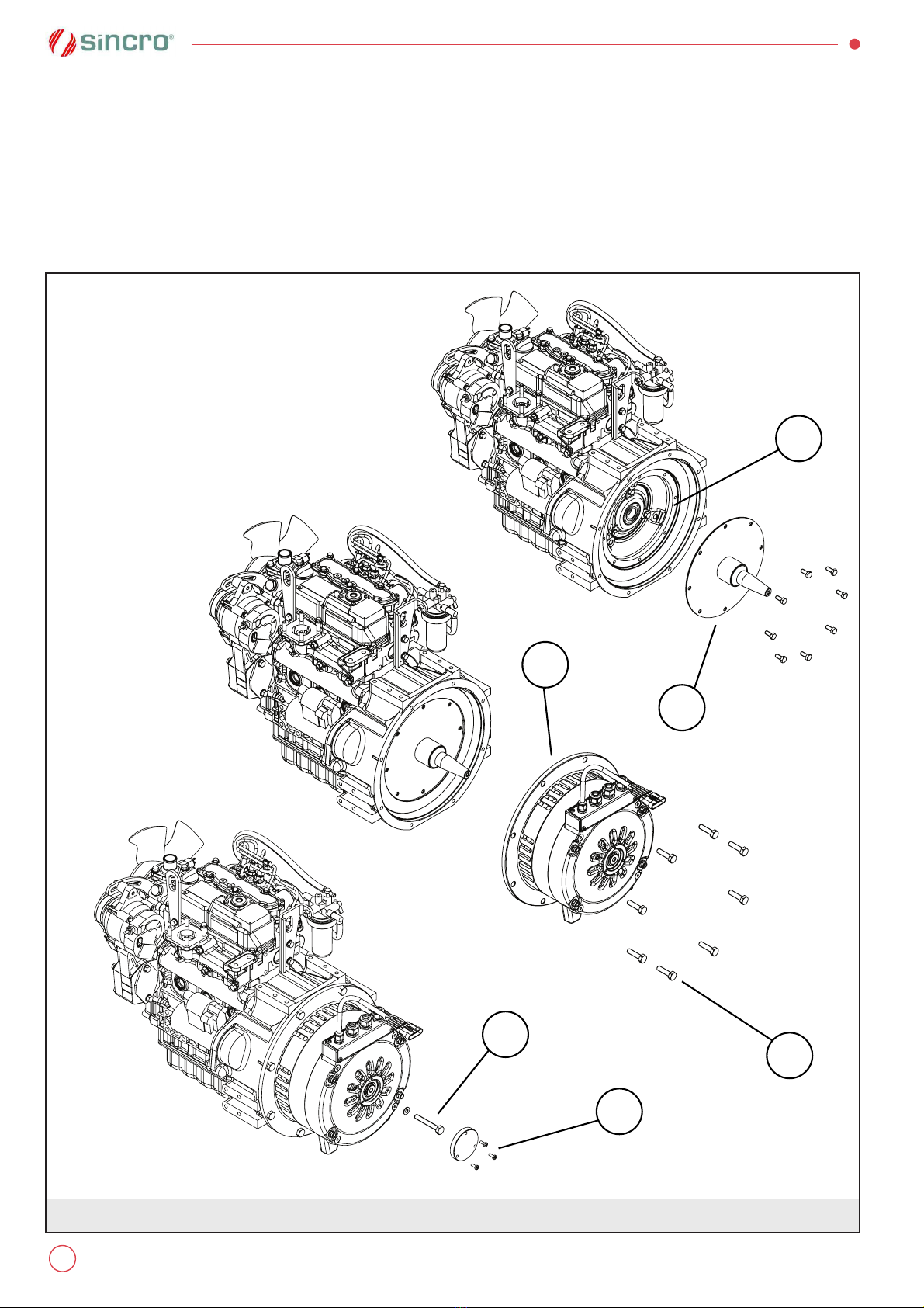
3.3.1 Montaggio e smontaggio forma SAE
Fissare il kit dischi SAE (1 •g.3.1) al volano (2 •g 3.1).
Fissare il generatore al motore mediante bloccaggio
della !angia SAE (3 •g 3.1).
Attenzione: viteria non inclusa nell’imballo.
Applicare la vite (4 •g 3.1) per il •ssaggio assiale del
rotore avvitandola sull’albero del kit dischi SAE con
coppia di serraggio 20-25 Nm.
Vibrations induced by the engine are complex and if
added to the generator’s one, can reach damaging lev-
els for the entire system. Therefore the plant engineer
must take all necessary measures to ensure alignment
and provide a •rm base and supports in order to pre-
vent vibrations from exceeding the standard (ISO 8528-
9).
Ensure that generator doesn’t take-in hot air expelled
by itself or by engine.
Contact our technical department to resolve problems
incurred.
CAUTION!
Assembling and disassembling pro-
cedures must be carried out solely by
quali•ed personnel by means and tools
suitable for the purpose.
3.2 Handling, lifting and storage
Handle the generator with suitable equipment, using
the shield and/or the !ange as structural parts to lift the
machine.
If the generator is not immediately commissioned, it
should be stored in a sheltered, clean and dry place,
free of vibrations.
After four years from the date of supply, and with the
motor stored in good conditions, it is advisable to re-
place the bearings and check if the insulation resist-
ance is higher than 10 MΩ. Under unfavourable stor-
age conditions, this check-time is reduced by half.
3.3 Coupling con•gurations
The generator is con•gured both for SAE and IMB35
coupling.
CAUTION!
Before the assembling make sure that
coupling surfaces for both generator
and engine are compatible, regular and
perfectly clean.
3.3.1 Assembly and disassembly instruc-
tions for SAE coupling
Fix the SAE disk (1 •g 3.1) to the !ywheel (2 •g 3.2).
Fix the generator to the motor by •xing the SAE !ange
(3 •g 3.1).
Caution: screws available on the market and not in-
cluded in the package.
Lock axially the rotor by •xing the screw (4 •g 3.1) to
the SAE kit. Use a tightening torque equal to 20-25Nm.
Plug the cap (5 •g 3.1) on the rear shield using the
screws supplied with the generator.
To dismantle the generator see the following instruc-
tions .
Disassemble the cap (5 •g 3.1) from the rear shield.
8
Montare il tappo (5 !g 3.1) di chiusura sullo scudo po-
steriore usando la viteria fornita assieme al generatore.
Per lo smontaggio eseguire le operazioni di seguito
elencate.
Togliere il coperchietto (5 !g 3.1) dallo scudo posterio-
re.
Togliere la vite di bloccaggio assiale (4 !g 3.1) del ro-
tore.
Unscrew the rotor axial locking screw (4 •g 3.1).
Substitute an M10 screw with 60 mm minimum legth to
the above screw (4 •g 3.1) and •x it until the rotor will
be dissasemble from the conical shaft of theSAE kit.
Dismantle the generator from the engine removing the
screws (6 •g 3.1) of the SAE •ange (3 •g 3.1).
Dismantle the SAE disk (1 •g 3.1) from the •ywheel of
the engine (2 •g 3.1).
2
1
3
4
5
6
Fig. 3.1
9
Avvitare al posto della vite (4 •g 3.1) una vite M10 di
lunghezza minima 60 mm •no a disaccoppiare il rotore
dall’albero conico del kit SAE.
Disassemblare il generatore dal motore svitando le viti
(6 •g 3.1) della •angia SAE (3 •g 3.1).
Smontare il kit dischi SAE (1 •g 3.1) dal volano del mo-
tore (2 •g 3.1).
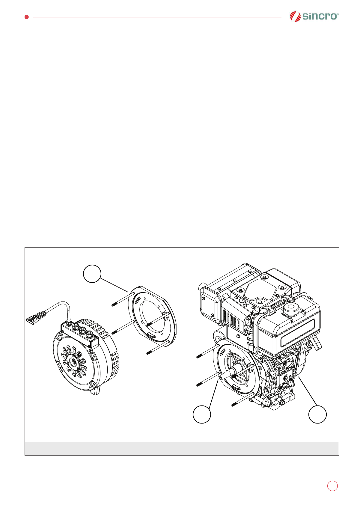
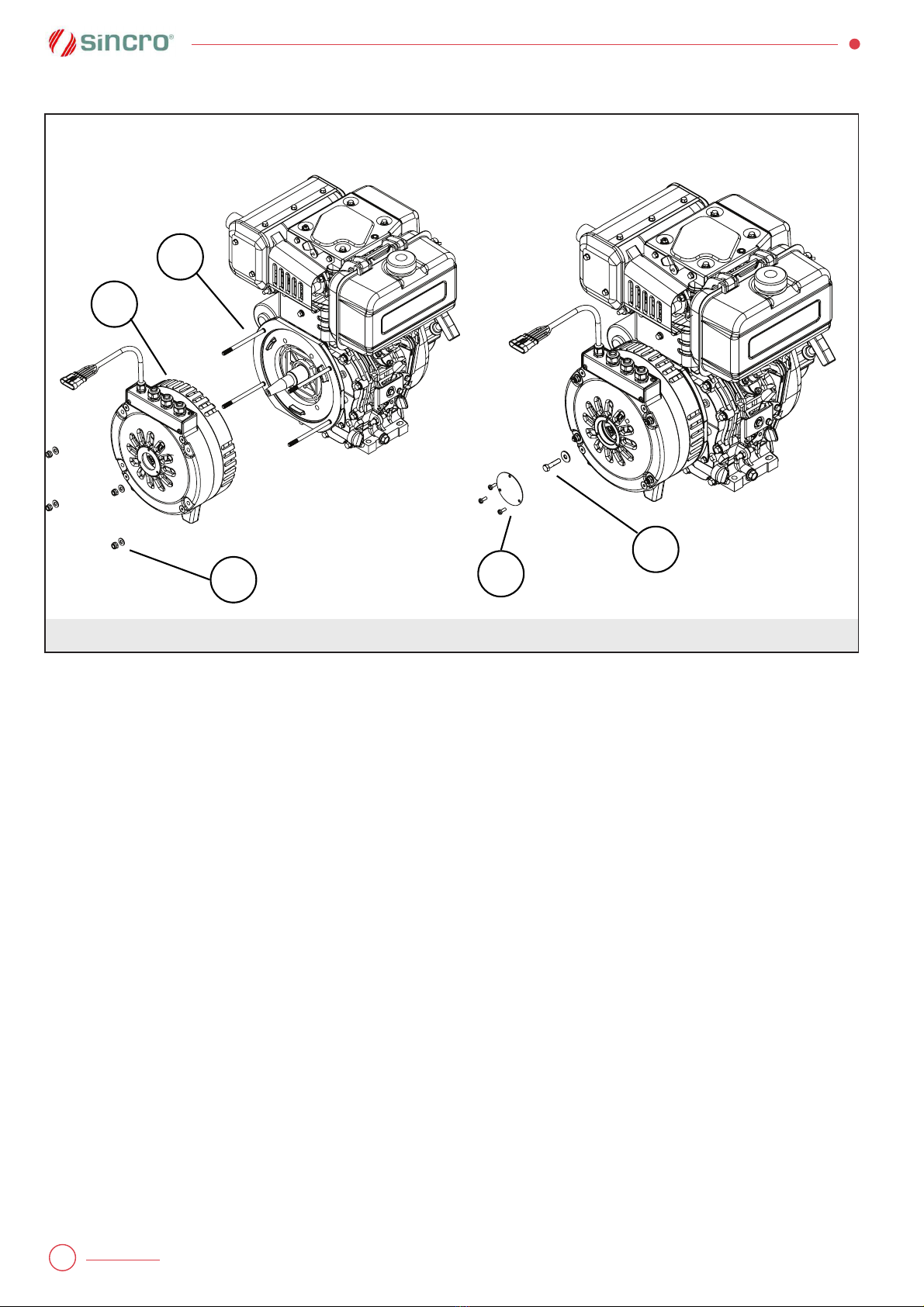
3.3.2 Montaggio e smontaggio forma IMB35
Una volta disimballato il generatore, disassemblare la
•angia anteriore (1 •g 3.2).
Fissare la •angia anteriore (1 •g 3.2) al motore (3 •g
3.2) mediante l’apposita •angiatura presente su di
esso, svitando le viti (2 •g 3.2). Attenzione: la bullone-
ria non è inclusa nell’imballo. Si consiglia bulloneria a
basso ingombro.
Assemblare l’alternatore (4 •g. 3.3) alla •angia (1 •g.
3.3) ponendo attenzione a centrare i prigionieri nelle
apposite asole. Successivamente •ssare il generatore
(4 •g 3.3) allo scudo (1 •g 3.3) mediante dadi e rondelle
(2 •g 3.3) svitate precedentemente.
Bloccare assialmente il rotore usando l’apposita vite e
rondella (6 •g 3.3) da •ssare sull’apposita sede presen-
te sull’albero conico del motore. Utilizzare una coppia
di serraggio pari a 20-25Nm.
Montare il tappo (7 •g 3.3) di chiusura sullo scudo po-
3.3.2 Assembly and disassembly instruc-
tions for IMB35 coupling
After unpacking the generator remove the D.E. shield.
(1 •g.3.2)
Fix the D.E. shield (1 •g. 3.2) to the engine (3 •g 3.2)
using the screws (2 •g 3.2). Pay attention: bolts aren’t
enclosed into generator package. Reduced dimensions
bolts use is recommended.
Assemble the generator (4 •g. 3.3) to the shield (1 •g.
3.3) paying attention to center the prisoners in the slots
on the shield. Then •x the generator (4 •g 3.3) to the
shield (1 •g 3.3) using bolts and washers (2 •g 3.3)
previously unscrewed.
Lock axially the rotor by turning the self-locking screw
and washer (6 •g 3.3) on the groove on the motor coni-
cal shaft. Use a tightening torque equal to 20-25Nm.
Plug the cap (7 •g 3.3) on the rear shield using the
screws supplied with the generator.
Mount assembly on vibration dampers (available on the
market and not included in the package) taking care the
correct leveling between engine and generator.
To dismantle the generator follow the instructions in
Fig. 3.2
1
1 2
10
Fig. 3.3
1
4
5
6
7

11
steriore usando la viteria fornita assieme al generatore.
Supportare il gruppo elettrogeno con adeguati antivi-
branti (reperibili in commercio e non inclusi nell’imballo)
curando il corretto livellamento di motore e generatore.
Per lo smontaggio eseguire in ordine inverso le opera-
zioni descritte sopra.
3.4 Collegamenti e terminali
I generatori vengono forniti con cavi uscenti.
Il collegamento elettrico va eseguito a macchina fer-
ma, rispettando scrupolosamente le norme di sicurezza
precisate nella norma IEC 60204-1.
PERICOLO!
Per il collegamento a massa fare ri-
ferimento alle corrispondenti norme
locali in materia. Collegamenti a mas-
sa o di protezione eseguiti in modo
errato possono portare a lesioni o al
decesso.
Collegare il conduttore di messa a terra sul morsetto
con il simbolo:
Il quadro elettrico della macchina avente il generatore
PMG140K come componente, deve essere messo a
massa secondo le normative vigenti nel paese in cui la
macchina stessa viene prodotta.
IMPORTANTE!
Impiegare cavi aventi sezione ade-
guata a sopportare la corrente ero-
gata dal generatore evitando sovra-
riscaldamenti e cadute di tensione
eccessive.
Impedire che i cavi trasmettano sollecitazioni meccani-
che al generatore.
reverse order.
3.4 Cabling and terminals
Generators are equipped with outgoing leads.
Electrical wiring has to be carried out when the ma-
chine is still, respecting scrupulously the safety warn-
ings given in the IEC 60204-1 standard.
DANGER!
Follow local regulations on earthing for
the ground connection. An inef!cient
earth connection can cause injury or
death.
Earthing is to be carried out to the terminal with the
corresponding symbol:
The earthing of the electrical panel, in machines that
use PMG140K generator as a component, must be car-
ried out in accordance with local (national) regulations
in use.
IMPORTANT!
Use cables which have an adequate
cross-section to bear the current of the
generator thus avoiding overheating
and/or power failure.
Stop the cables from transmitting mechanical stress to
the generator.

12
3.5 Veri•ca della resistenza di
isolamento
Prima della messa in servizio e dopo lunghi periodi di
inattività o immagazzinamento si deve veri!care che la
resistenza d’isolamento dell’avvolgimento alla tempe-
ratura ambiente di circa 25°C sia superiore a 50 M".
Se vengono rilevati valori inferiori, l’avvolgimento pre-
senta una eccessiva e pericolosa umidità per cui è ne-
cessario essiccarlo ad una temperatura di 60 - 70°C,
ricorrendo ad una ditta specializzata. Eseguire l’essic-
cazione del solo avvolgimento.
3.6 Messa in marcia
Prima della messa in servizio veri!care l’allineamen-
to con gli organi accoppiati, le connessioni e il colle-
gamento per la messa a terra. All’atto della messa in
funzione porre attenzione ad eventuali rumori anomali
che potrebbero indicare un allineamento non corretto
del generatore.
ATTENZIONE!
Non toccare il generatore durante il
funzionamento e subito dopo l’arre-
sto del gruppo, in quanto potrebbero
esservi delle super•ci a temperatura
elevata.
AVVERTENZA!
Dopo aver messo in servizio il gene-
ratore accertarsi che non superi la
potenza nominale in targa. Non so-
vraccaricare il generatore anche se
per tempi brevi.
4 PRINCIPIO DI FUNZIONAMENTO
I generatori della serie PMG140K sono generatori sin-
croni a magneti permanenti. L’eccitazione è garantita
dai magneti permanenti e quindi la macchina non ne-
cessita dell’avvolgimento di eccitazione sul rotore. La
struttura del generatore risulta così più semplice e ro-
busta. La tensione a vuoto generata dalla macchina è
quindi proporzionale alla velocità di rotazione.
I generatori sincroni a magneti permanenti non hanno
un sistema di regolazione della tensione di uscita.
In targa è indicata la tensione a carico.
3.5 Insulation resistance check
Before the commissioning and after long periods of
inactivity or storage it must be checked that the insula-
tion resistance of the winding to a room temperature of
about 25°C is over 50 MΩ.
Lower values indicate that the winding has excessive,
dangerous humidity and so it should be dried at 60 -
70°C by a specialised company. Dry only the stator
winding.
3.6 Initial start-up
Before commissioning, check the correct alignment of
the coupled elements, as well as the correct connec-
tions and earthing. During the initial start-up, pay par-
ticular attention for any unusual noises that might signal
an incorrect alignment of the generator.
CAUTION!
Do not touch the generator while in
operation and straight after the gener-
ating set has stopped because certain
parts may still be very hot.
WARNING!
After the initial start-up of the genera-
tor, make sure that the power does not
exceed the rated one on the nameplate.
Do not overload the generator, even for
a short period of time.
4 OPERATING PRINCIPLE
The generators of the PMG140K series are synchro-
nous generators with permanent magnets. The excita-
tion is provided by permanent magnets and therefore
the machine does not require excitation of the winding
on the rotor. The structure of the generator is thus more
simple and robust. The open circuit voltage generated
by the machine is then proportional to the speed of ro-
tation (View the data sheet for more information).
Synchronous generators with permanent magnets do
not have a regulating system for the output voltage.
On the nameplate is written the voltage at load ope-
ration.
13
5 ASSISTENZA E MANUTENZIONE
AVVERTENZA!
Qualsiasi intervento sul generatore
deve essere effettuato a macchina
ferma.
È buona regola veri!care periodicamente che il genera-
tore funzioni senza vibrazioni o rumori anomali, che l’e-
rogazione di corrente non si discosti da quanto indicato
in targa e che sul generatore non siano presenti tracce
di polvere, olio o altre impurità.
Accertarsi che i fori scarico condensa siano liberi.
AVVERTENZA!
Non toccare il generatore durante il
funzionamento e subito dopo l’arre-
sto del gruppo in quanto vi potreb-
bero essere super"ci a temperatura
elevata.
Le macchine elettriche rotanti pre-
sentano parti pericolose in quanto
poste sotto tensione e con parti in
movimento durante il funzionamen-
to. Pertanto possono causare gravi
danni a persone o cose:
- un uso improprio
- la rimozione delle protezioni e lo
scollegamento dei dispositivi di
protezione
- la carenza di ispezioni e manu-
tenzione.
5.1 Cuscinetti
Se presenti, la durata dei cuscinetti dipende dalle vibra-
zioni e dai carichi assiali e radiali ai quali sono sottopo-
sti, dalle condizioni di lavoro e dalla corretta procedura
di ingrassaggio. Accertarsi che le condizioni di lavoro
del generatore rispettino quelle indicate in targa. L’e-
ventuale montaggio e smontaggio degli organi di ac-
coppiamento e dei cuscinetti devono essere effettuati
secondo modalità e con attrezzi adatti allo scopo (infor-
mazioni disponibili su richiesta).
Il generatore non è provvisto di lubri!catore, quindi i
cuscinetti vanno sostituiti seguendo le indicazioni della
tabella 8.7. In tale occasione pulire i supporti e veri!ca-
re che non siano presenti usure sui mozzi degli scudi/
"angie.
AVVERTENZA!
La durata dei cuscinetti è fortemente
in#uenzata dalle condizioni e dall’am-
biente di lavoro.
5 MAINTENANCE AND SERVICE
WARNING!
All generator maintenance operations
must be made only at standstill.
It is a good rule to check at regular intervals that the
generator is working without vibrations or strange nois-
es, that the current absorption does not exceed the one
shown on the nameplate and that there aren’t traces of
dust, oil or other impurities on the generator.
Check that the condensation drain holes are free.
WARNING!
Never touch the generator during op-
eration or immediately after stopping
it because some surfaces might still
be very hot. Electric rotating machines
have dangerous parts. When operating
they are under voltage and have rotat-
ing components. Therefore:
- the improper use
- the removal of protective covers
and the disconnection of protec-
tion devices
- the inadequate inspection and
maintenance.
can cause personal injury or property
damage.
5.1 Bearings
If present, the bearing’s lifespan is closely linked to the
working conditions, the degree of vibrations, the axial
and radial loads and the proper regreasing procedure.
Make sure that the working conditions of the genera-
tor comply with those stated on the nameplate. In case
of assembly and disassembly of coupling organs and
bearings the procedure must be carried out with meth-
ods and tools suitable for the purpose (information
available on request).
The generator is not provided with lubricator, for this
reason the bearings must be replaced according to Ta-
ble 8.7. Clean the bearing housing and check that no
abrasion is visible on the hubs of the shields/!anges.
WARNING!
A bearings lifespan is closely linked to
the working conditions and environ-
ment.

14
AVVERTENZA!
Lunghi periodi di permanenza in un
ambiente caratterizzato dalla presen-
za di vibrazioni possono danneggia-
re le sfere e le sedi di rotolamento.
La presenza di una umidità troppo
elevata può causare l’emulsione del
grasso e favorire effetti di corrosio-
ne.
AVVERTENZA!
Intense vibrazioni causate dal motore
o da un errato allineamento dei com-
ponenti del gruppo elettrogeno sotto-
pongono il cuscinetto a sollecitazioni
che ne riducono la vita.
5.2 Risoluzione dei problemi
INCONVENIENTI CAUSE COSA FARE
La tensione del
generatore a vuoto è
troppo alta/bassa.
1) Velocità troppo elevata/
bassa.
2) temperatura troppo bassa/
alta
1) Controllare velocità e frequenza.
2) Controllare che la temperatura ambiente rientri
all’interno del campo speci!cato in targa.
La tensione del
generatore è corretta
a vuoto ma troppo
bassa a carico.
1) Possibile sovraccarico. 1) Veri!care che la corrente erogata non sia
superiore a quella in targa ed eventualmente ridurre
il carico.
La tensione del
generatore è instabile.
1) Contatti incerti.
2) Velocità del generatore
instabile.
3) Carico variabile.
1) Controllare le connessioni.
2) Veri!care se la velocità è costante. Regolare la
velocità del generatore agendo sul motore primo.
3) Controllare la stabilità del carico.
Sovratemperature
elevate negli
avvolgimenti.
1) Possibile sovraccarico.
2) Scarso raffreddamento
1) Veri!care che la corrente erogata non sia
superiore a quella in targa ed eventualmente ridurre
il carico.
2) Controllare il circuito di ventilazione.
Macchina rumorosa. 1) Cuscinetti sovraccaricati.
2) Accoppiamento realizzato in
modo sbagliato.
3) Il generatore sta lavorando
al di sopra delle sue
prestazioni nominali.
1) Controllare i carichi assiali e radiali.
2) Veri!care e correggere l’accoppiamento.
3) Ridurre il carico.
Tab. 1
15
WARNING!
Long periods of sustained vibrations
can damage the bearing balls and their
seat. Too high humidity can emulsify
the grease and encourage corrosion.
WARNING!
Intense vibrations caused by the en-
gine bad alignment of the components
in the generating set put the bearing
under stresses that will reduce its lifes-
pan.
5.2 Troubleshooting
PROBLEM CAUSES WHAT TO DO
The voltage at no load is
too high/low
1) The speed is too high/low
2) Temperature too low/high.
1) Check speed/frequency.
2) Check if the ambient temperature is inside the
range speci•ed in the nameplate.
The generator voltage at
no load is correct but too
low when connecting the
load (stand-alone mode).
1) Possible overload. 1) Make sure the generated current is not higher
than the rated one and possibly reduce the load.
Check the inverter parameters set-up.
The generator voltage is
unstable.
1) Poor contacts.
2) Unstable generator speed.
1) Check contacts.
2) Check if the speed is constant. Regulate the
speed of the generator acting on the prime mover.
The temperature rise in
the winding is too high.
1) Possible overload.
2) Poor cooling
1) Make sure the generated current is not higher
than the rated one and possibly reduce the load.
Check the inverter parameters set-up.
2) Check the cooling system.
Machine noisy. 1) Over loaded bearings.
2) Faulty coupling.
3) The generator is
working above its rated
performances.
1) Check axial and radial loads.
2) Check and •x the coupling.
3) Reduce the load.
Tab. 1
16
6 DISMANTLING
Most of generator parts are made of steel, cast iron
and copper. All materials should be eliminated in com-
pliance with the local dispositions. When dismantling
the generator pay attention to the permanent magnet
in the rotor. To aid recovery of the material, it is best to
classify it by type (I.e. steel, copper, aluminium, plastic,
etc.). When dismantling the machine, contact an au-
thorised scrap dealer and ensure that no parts of the
generator are dumped in the environment.
DANGER!
The disassembly of the generator
must NOT be carried out by people
with pacemakers or any other im-
planted medical electronic device.
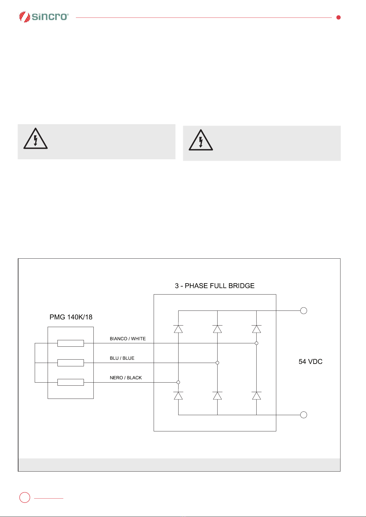
7 CONNECTIONS
7.1 Power connections
The lead wires for the power connection come out from
the rear shield. They must be connected to a three
phase full rectifier bridge (fig. 7.1)
6 DEMOLIZIONE E SMALTIMENTO
L’alternatore è costituito in massima parte da acciaio,
ghisa e rame. L’eliminazione dei materiali va fatta nel
rispetto delle norme vigenti. Nel caso di demolizione
del generatore porre attenzione ai magneti permanenti
posizionati sul rotore. E’ opportuno in caso di recupero
materiali, che vengano separati per tipologia (acciaio,
rame, alluminio, plastica, etc.). Rivolgersi ad un’agen-
zia di smaltimento. Assicurarsi che nessuna parte del
generatore venga dispersa nell’ambiente.
PERICOLO!
Persone con peacemaker e/o altri di-
spositivi elettronici biomedicali non
possono eseguire lo smontaggio del
generatore.
7 CONNESSIONI
7.1 Collegamento cavi di potenza
Dallo scudo posteriore del generatore escono i cavi di
potenza i quali vanno collegati a un ponte raddrizzatore
trifase (fig. 7.1).
Fig. 7.1
+
-
17
CUSCINETTI - BEARINGS
Modello/ Type Intervallo di sostituzione consigliato (ore)
Advised bearing change interval (hours)
L.Opposto
Opposite Side 6205 2RS C3 20000
Tab. 7.2
COPPIE DI SERRAGGIO Nm - TIGHTENING TORQUES Nm
Applicazione
Application
Diametri di filettatura
Thread diameter
M5 M6 M8 M10 M12 M16 M20 M24
Connessioni meccaniche (acciaio classe 8.8)
Mechanical connections (steel grade 8.8) 6 9 23 45 80 200 350 620
Tab. 7.3

18
RICAMBI ED ASSISTENZA
Procedura e indirizzi di riferimen-
to per richieste di assistenza.
Il nostro Servizio di Assistenza for-
nisce completa consulenza tecnica.
Assicurarsi, per richieste di Assi-
stenza in garanzia, di disporre dei
dati identi!cativi del generatore, del
suo numero di serie e del numero
dell’ordine di produzione riportati
sulla targhetta. La lista dei centri di
assistenza autorizzati è disponibile
nel nostro sito internet: www.sogae-
nergyteam.com. Nel caso di guasti
o anomalie di funzionamento delle
macchine Soga, il Cliente è invi-
tato ad interpellare il nostro “Ser-
vizio Assistenza” telefonando allo
0039-0444-747700. Se, dopo tale
contatto, risultasse necessaria la
restituzione del prodotto, il nostro
“Servizio Assistenza” fornirà al
Cliente un numero di “Rientro Mate-
riale Autorizzato” (RMA), che dovrà
essere riportato sui documenti di
accompagnamento del materiale.
Prodotti resi senza aver eseguito
la descritta procedura verranno
respinti al mittente dal magazzi-
no accettazione. Per l’eventuale
concessione della garanzia è in-
dispensabile che la Soga sia con-
tattata esclusivamente dal proprio
Cliente. Richieste di riparazione
provenienti direttamente dall’utiliz-
zatore !nale saranno in ogni caso
considerate NON in garanzia.
Prima di procedere a riparazioni
verrà comunicato un preventivo e si
attenderà l’autorizzazione da parte
del Cliente.
Resa della merce per riparazione
La merce resa viaggia esclusiva-
mente a spese e a rischio del Clien-
te indipendentemente dalla conces-
sione dell’intervento in garanzia.
Curare che le macchine siano in
ordine e pulite. Si raccomanda di
restituire il materiale entro un imbal-
lo adeguato, curando di proteggere
il prodotto dagli urti.
SPARE PARTS AND
AFTERSALES
Aftersales procedure and con-
tact addresses
Our Aftersales Service provides
a comprehensive technical advise
service. When requesting as-
sistance under warranty make sure
that the generator identi•cation data
is on hand including its serial num-
ber and production order as shown
on the label. The list of authorised
aftersales assistance centres can
be found on our homepage: www.
sogaenergyteam.com. Whenever
any Soga machine malfunctions,
the client is invited to contact our
“Assistance Service” by calling
0039 0444 747700. If the deci-
sion is made to return the prod-
uct, we will provide you with an
“Authorized Material Return” (RMA)
number that must be included in
the delivery document that ac-
company material. Products that
have been returned without fol-
lowing the procedure above will
be returned to sender. In order to
obtain coverage under warranty,
Soga must be contacted exclusive-
ly by its authorized dealers or by
its direct customers. Requests for
repairs received directly from •nal
user clients will be considered OUT-
SIDE the terms of warranty cover-
age. Prior to performing repair, an
estimation will be provided and
authorization must be received
from the authorized dealer before
proceeding with the repair.
Shipment
All products to be repaired are
shipped at the risk and expense
of the Client regardless of whether
warranty coverage will be claimed
or not. The client must make sure
that the machines sent for repair
are in good order and clean. We
recommend returning the products
in adequate packaging that en-
sures protection against impact.
PIÈCES DE RECHANGE ET
SERVICE APRÈSVENTE
Procédures et adresses de réfé-
rence pour demandes de service
après-vente
Notre Service Après-Vente four-
nit un conseil technique complet.
S’assurer pour les demandes de
Service Après- Vente sous ga-
rantie, de disposer des données
d’identi!cation du générateur, de
son numéro de série et du numéro
de l’ordre de production indiqués
sur l’étiquette. La liste des centres
après-vente agréés est disponible
sur notre site internet : www.sogae-
nergyteam.com En cas de pannes
ou d’anomalies de fonctionnement
des machines Soga, le client est
invité à contacter notre « Service
Après-Vente » en téléphonant au
0039-0444-747700. Si, après ce
contact, la restitution du produit
se révèle nécessaire, notre «
Service Après-Vente » fournira au
client un numéro de « Retour Maté-
riel Autorisé » (RMA), qui devra être
indiqué sur les documents joints au
matériel. Les produits renvoyés
sans avoir effectué la procédure
décrite seront renvoyés à l’expédi-
teur par le magasin de réception.
Pour l’accord éventuel de la
garantie, il est indispensable que
Soga soit contactée exclusivement
par son client. Les demandes de ré-
paration provenant directement de
l’utilisateur !nal seront considérées
dans tous les cas comme interven-
tions HORS GARANTIE. Avant de
procéder à des réparations, un de-
vis sera envoyé au Client qui devra
communiquer son acceptation.
Renvoi au siège pour réparation
En cas de retour de matériel, la
marchandise voyage exclusi-
vement aux frais et aux risques
du Client indépendamment de la
concession de l’intervention sous
garantie. Veiller à ce que les ma-
chines soient propres en ordre.
Il est recommandé de restituer le
matériel dans un emballage adé-
quat en veillant à protéger le pro-
duit contre les chocs.

19
ERSATZTEILE UND
KUNDENDIENST
Prozedur und Referenzadres-
sen zur Anforderung von Kun-
dendienstleistungen
Unser Kundendienst bietet eine um-
fassende technische Beratung. Zur
Beantragung von Kundendienstleis-
tungen im Rahmen der Garantie
sicherstellen, dass alle Kenndaten
des Generators, seine Seriennum-
mer und die Nummer des Pro-
duktionsauftrags vorliegen, wel-
che dem Aufkleber entnommen
werden können. Die Liste der au-
torisierten Kundendienst-Zentren
•nden Sie auf unserer Internet-Site
www.sogaenergyteam.com
Im Falle von Defekten oder
Funktionsanomalien der Soga-
Maschinen wenden Sie sich bitte
an unsere “Kundendienstabteilung”
unter der Telefonnummer 0039-
0444-747700. Falls sich ergeben
sollte, dass das Produkt eingesandt
werden muss, erhalten Sie von un-
serer “Kundendienstabteilung” eine
Nummer für die “autorisierte Rück-
gabe” (RMA), welche auf den Be-
gleitpapieren der Ware angegeben
werden muss.
Waren, die nicht nach dieser Pro-
zedur eingesandt werden, können
nicht angenommen werden.
Für die eventuelle Gewährung von
Garantieleistungen ist es erfor-
derlich, dass die Firma Soga von
ihrem direkten Kunden kontaktiert
wird. Reparaturanträge, die direkt
vom Endbenutzer eingehen, kön-
nen NICHT als Garantie- leistungen
behandelt werden.
Vor der Reparatur wird ein Kosten-
vor- anschlag erstellt und die Auto-
risierung des Kunden abgewartet.
Einsenden von produkten an den
!rmensitz zur reparatur
Der Transport der eingesandten
Ware geht ausschließlich auf Kos-
ten und Risiko des Kunden, unab-
hängig von der Genehmigung der
Garantieleistung. Die Maschinen
müssen sauber in Ordnung sein.
Das Material muss so verpackt
sein, dass der Inhalt gegen Stoß-
einwirkungen geschützt ist.
RECAMBIOS Y
ASISTENCIA
Procedimientos y direcciones
de referencia para solicitudes de
asistencia.
Nuestro Servicio de Asistencia
proporciona una completa ase-
soría técnica. Antes de solicitar
Asistencia en garantía comprobar
que se dispone de los datos de
identi!cación del generador, de su
número de serie y del número de
pedido de producción indicados
en la etiqueta. La lista de los cen-
tros de asistencia autorizados se
encuentra en nuestro sitio internet:
www.sogaenergyteam.com
En caso de averías o anomalías de
funcionamiento de las máquinas
Soga, le rogamos que interpele
nuestro “Servicio de Asistencia”
llamando por teléfono al número
0039-0444 747700. Si, tras haber-
se puesto en contacto, fuera ne-
cesaria la restitución del pro- ducto,
nuestro “Servicio de Asisten- cia” le
facilitará un número de “Retorno de
Material Autorizado” (RMA), que se
deberá indicar en los documentos
que acompañen el material.
El almacén de aceptación devolve-
rá al remitente los productos que
hayan sido enviados al fabricante
sin haber seguido el procedimiento
descrito.
Para la eventual concesión de la
garantía es indispensable que sea
exclusiva- mente el cliente a po-
nerse en contacto con Soga. So-
licitudes de reparación procedentes
directamente del usuario !nal se
considerarán en todo caso como
NO en garantía.
Antes de efectuar reparaciones se
comunicará un presupuesto y se
esperará la autorización del Cliente.
Expedicòn de restituciòn al fabri-
cante para reparaciòn
La mercancía devuelta viaja exclu-
sivamente por cuenta y riesgo del
Cliente independientemente de que
se conceda o no la reparación en
garantía. Las máquinas tienen que
estar en buen estado y limpias. El
material se debe restituir adecua-
damente embalado, protegiendo el
producto contra golpes.

20
GARANZIA
Se non diversamente concordato
in sede contrattuale, valgono le
seguenti condizioni:
La Soga garantisce ai propri clienti
le macchine, prodotte al suo in-
terno, per un periodo di 18 mesi a
decorrere dalla data di fatturazione
Soga; oppure 12 mesi a decorrere
dalla data di prima messa in fun-
zione; quale delle due avviene per
prima. Si precisa che detta garan-
zia è rivolta ai soli clienti della Soga
ai quali direttamente risponde. La
Soga non riconosce direttamente
la garanzia ad alcun soggetto che,
pur in possesso dei suoi prodotti,
non li abbia da essa acquistati di-
rettamente. Entro i suddetti termini
la Soga si impegna a fornire gratu-
itamente pezzi di ricambio di quelle
parti che, a giudizio della Soga o di
un suo rappresentante autorizzato,
presentino difetti di fabbricazione
o di materiale oppure, a suo giu-
dizio, ad effettuarne la riparazione
direttamente o per mezzo di of!cine
autorizzate senza assumersi alcun
onere per il trasporto. Rimane co-
munque esclusa qualsiasi altra for-
ma di responsabilità o obbliga- zio-
ne per altre spese, danni e perdite
dirette o indirette derivanti dall’uso
o dalla impossibilità d’uso dei pro-
dotti, sia totale che parziale.
La riparazione o la fornitura sostitu-
tiva non prolungherà, né rinnoverà
la durata del periodo di garanzia. La
garanzia decadrà: qualora si ma-
nifestassero inconvenienti o guasti
dovuti ad imperizia, utilizzo oltre ai
limiti delle prestazioni nominali, se
il prodotto avesse subito modi!che
o se dovesse ritornare disassem-
blato o con dati di targa alterati o
manomessi.
WARRANTY
Unless otherwise speci•cated in
the contract agreement, the fol-
lowing conditions should be ap-
plied:
Soga guarantees the own machines
for a period of 18 months starting
from the invoice date of Soga or 12
months starting from the •rst start
up; whichever occurs •rst.
We con•rm that warranty is di-
rected only to Soga customers to
which we respond. Soga does not
grant warranty to those who have
not directly purchased the prod-
uct from the factory, in spite of the
possession of it. Within the above
mentioned terms, Soga commits
itself to supply free of charge those
spare parts that, according to its
judgment or to the one of an author-
ized representative, appear with
manufacturing or material defects
or, always to its judgment, to direct-
ly or through an authorized center
carry out the repairing without un-
dertaking transport costs. We any-
how exclude forms of responsibility
or obligation for other costs, dam-
ages and direct or indirect loss
caused by total or partial usage or
impossible usage of the products.
The repairing or the substitution
will not extend or renew the war-
ranty duration. Warranty will not be
granted: whenever break-downs or
problems may appear because of
lack of experience, usage over the
nominal performances, if the prod-
uct had been modi•ed or should
return incomplete, disassembled or
with modi•ed nameplate data.
GARANTIE
Sauf indication contraire dans le
contrat, les conditions suivantes
s’appliquent:
Soga garantit à ses clients les ma-
chines, produits par ses soins, pour
une période de 18 mois à compter
de la date de facturation par Soga
ou 12 mois à compter de la
première mise en service; cela de-
pende da la condition que si veri!e
en premiére. Nous précisons que
cette garantie ne s’adresse qu’aux
clients Soga aux- quels elle répond
directement. Soga ne reconnaît pas
la garantie aux sujets qui, quels
qu’ils soient, bien qu’étant en pos-
session de ses produits, ne les lui
ont pas achetés directement. Au
cours des périodes susmen-
tionnées, Soga s’engage à four-
nir gratuitement les pièces de re-
change des parties qui, de l’avis de
Soga ou d’un de ses représentants
agréés, présentent des défauts de
fabrication ou de matériau ou bien,
à sa discrétion, elle s’engage à en
effectuer la réparation directement
ou par l’intermédiaire d’ateliers au-
torisés, sans soutenir aucun frais
de transport.
Toute autre forme de responsabilité
ou d’obligation inhérente à d’autres
frais, dommages ou pertes directes
ou indirectes dérivant de l’utilisa-
tion ou de l’impossibilité, totale ou
partielle, d’utiliser les produits reste
exclue. La réparation ou la fourni-
ture de remplacement ne prolon-
gera pas et ne renouvellera pas
la période de garantie. La garantie
devient caduque: en cas d’inconvé-
nients ou de pannes liées à l’inex-
périence, d’utilisation au-delà des
limites des performances nomi-
nales, si le produit a subi des modi-
!cations et est renvoyé démonté
ou avec les données de la plaque
signalétique altérées ou modi!ées.
Table of contents
Other Sincro Portable Generator manuals

Sincro
Sincro ET-R Series User manual

Sincro
Sincro R80 Series User manual

Sincro
Sincro SK 225 User manual

Sincro
Sincro SK400 Series User manual

Sincro
Sincro R80 Series User manual

Sincro
Sincro ET Series User manual

Sincro
Sincro EW-DC Series User manual

Sincro
Sincro ARC 300 Series User manual

Sincro
Sincro ER Series User manual

Sincro
Sincro EP Series User manual


