SinoCastel IDD-213E User manual

IDD-213E User Manual
(Rev. 1.4)
Knowledge Gate for Information Technology
September, 2014

IDD-213E User Manual
Contents
1. Introduction ......................................................................................................................................................................
3
2. Specifications ...................................................................................................................................................................
4
2.1
External Interface ....................................................................................................................................................
4
2.2
Status Indicator .......................................................................................................................................................
5
2.3
Technical Parameters ............................................................................................................................................
6
3. Device Configuration ....................................................................................................................................................
8
3.1
PC Tool .......................................................................................................................................................................
8
3.2
SMS Instructions .....................................................................................................................................................
8
4. Installation Instruction.................................................................................................. .............................................
10
4.1
SIM Card Installation ..........................................................................................................................................
10
4.2
OBD Port .................................................................................................................................................................
11
4.3
Device Installation ...............................................................................................................................................
12
5. Functions ........................................................................................................................................................................
16
5.1
OBD Protocols ......................................................................................................................................................
16
5.2
Location Inquiry ...................................................................................................................................................
16
5.3
Regular GPS data reporting.............................................................................................................................
16
5.4
Regular G-Sensor Data Reporting ................................................................................................................
17
5.5
Regular Diagnostic Data Reporting ..............................................................................................................
17
5.6
DTCs Reporting ....................................................................................................................................................
17
5.7
Cell ID Reporting .................................................................................................................................................
17
5.8
GPS Data Reporting in Sleep Mode .............................................................................................................
18
5.9
Data storage/Supplementary Report in Dead zones.............................................................................
18
5.10
Trip Mileage ........................................................................................................................................................
18
5.11
Trip Fuel Consumption ...................................................................................................................................
18
5.12
Driving behavior monitoring ........................................................................................................................
18
5.13
Alarms and Events Reporting .......................................................................................................................
18
5.14 Working Mode ...................................................................................................................................................
19
5.15
GPS/Cellular Timer ............................................................................................................................................
19
5.16
SMS Alert ..............................................................................................................................................................
19
5.17
Google Map Link ...............................................................................................................................................
20
5.18
Remote Configuration ....................................................................................................................................
20
5.19
SMS Configuration ...........................................................................................................................................
20
5.20
PC Tool Configuration .....................................................................................................................................
20
6. Disclaimer .......................................................................................................................................................................
21
1

IDD-213E User Manual
7. Warranty .........................................................................................................................................................22
8. Statement .......................................................................................................................................................23
2

IDD-213E User Manual
1. Introduction
IDD-213E is an intelligent on-board diagnostic device with OBD II and SAE
J1939/J1708 (Heavy duty) compliant, it features plug-and-play technology, could read
diagnostic info from vehicle ECU and capture location data with built-in GPS, then
send them to backend server for real-time remote diagnostic and tracking purpose.
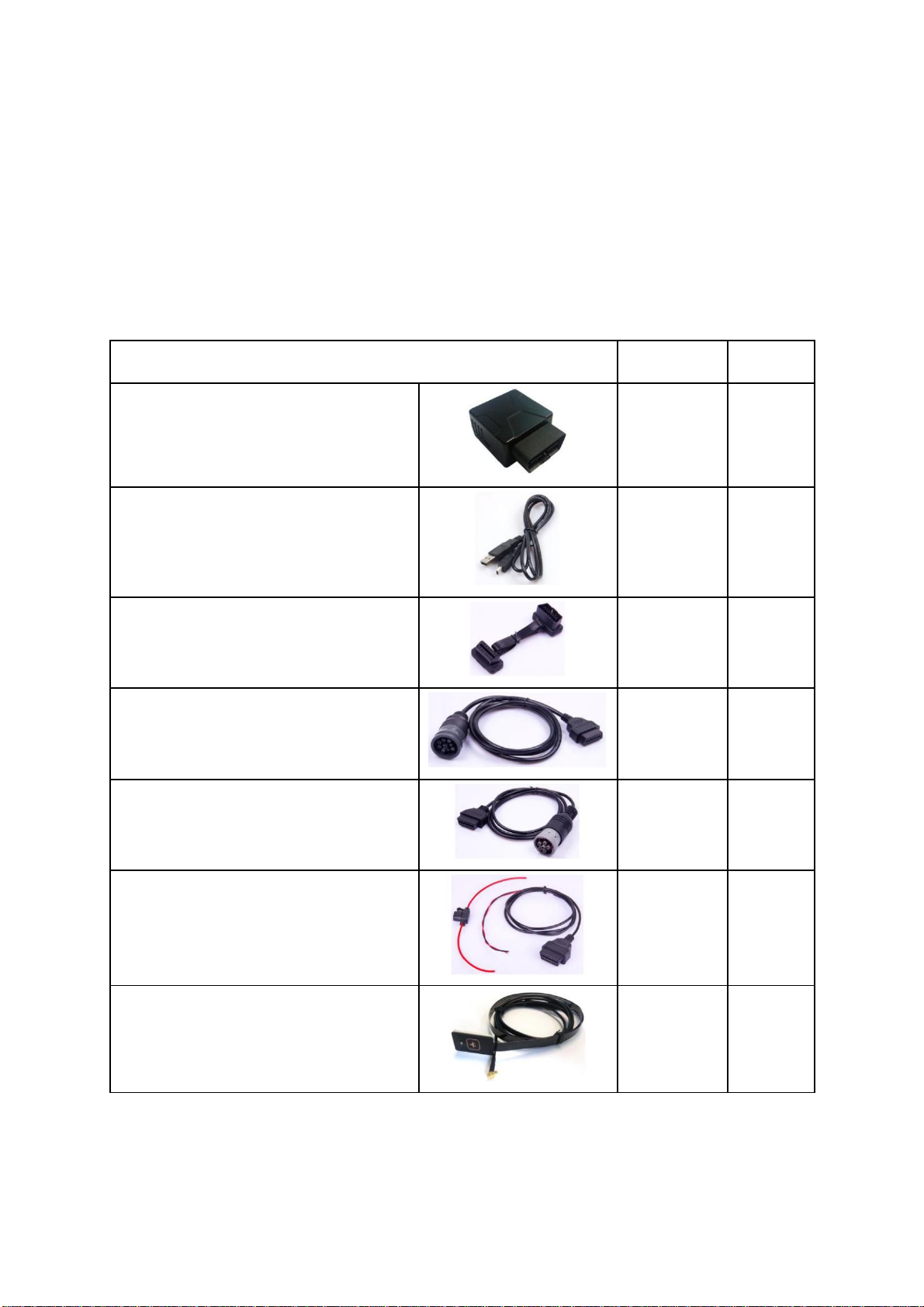
Packing List
Parts name
Quantity
Note
IDD-213E OBD Dongle
1
●
USB Configuration
1
○
Cable
OBD II extension cable
1
○
9-Pin deutsch wiring harness
1
○
6-Pin deutsch Wiring harness
1
○
Power cable (including 3A Fuse)
1
○
SOS button
1
○
Note: ● Standard configuration ○ Optional configuration
(Optional accessories will not be included if there is no indication in the order)
3

IDD-213E User Manual
2. Specifications
2.1 External Interface
Product appearance as follows:
OBD Connector
SOS Button
Interface
GPS LED USB Interface
Cellular LED
Power/OBD LED
SIM Card Slot
1. Standard OBD Connector
Connect to the 16 pin on-board Diagnostic Link Connector (DLC).
2. Mini USB interface
Connect to PC through USB configuration cable.
3. SOS button Interface
This is a SOS button interface, to connect the SOS button for emergency, interface
type is MMCX.
4. SIM Card slot
4

IDD-213E User Manual
2.2 Status Indicator
Indicator
Color
Status
Blinking (on 0.5s, off 0.5s) - Trying to access OBD
Power/OBD
Red
system or power off
LED
Solid on - Successful OBD communication
Solid off - Tracker mode or in sleep
Fast blinking (on 0.5s, off 0.5s) - No SIM card or
network searching
Cellular LED
Orange-red
Slow blinking (on 0.5s, off 2.5s) - Registered network
Solid on - Logged into the server
Solid off - Cellular off
Blinking (on 1s, off 1s) - GPS signal is good
GPS LED
Green
Solid on - Searching for GPS signal
Solid off - GPS off
One beep - Power on
Two beeps - Successful OBD communication
Three beeps - Successful log in
Buzzer
Beep
Four beeps - Trip end and stop OBD communication
Five beeps - Power off
Six beeps - Fail to access OBD system
Five beeps (short beep) - Alarm indication
5

6
IDD-213E User Manual
2.3 Technical Parameters
Mechanical
Dimension
63mm (L) x 48mm (W) x 28mm (H)
Weight
50g
OBD interface: 16 pin standard OBD II
Interface
Configuration interface: Mini USB
SOS button interface: MMCX
SIM card interface: Push-Push Type
Storage
2MB FLASH, can store up to 24000 GPS data
Data Transmission
Packet data (GPRS or HSPA) and SMS
Positioning Mode
GPS
SAE J1850 PWM
SAE J1850 VPW
ISO 9141-2
OBD Protocol
ISO 14230-4
ISO 15765-4
SAE J1939 (Heavy duty)
SAE J1587/J1708 (Heavy duty)
Working Voltage
9-36VDC
Power
Working Currency
Sleep Currency: <10mA@12/24VDC
Internal Battery
3.7V/160mA Lithium battery
3-axis Accelerometer
+/-2g、+/-4g、+/-8g、+/-16g
Channels: 48
Sensitivity: -163dBm
GPS
Accuracy: 5m CEP
Time to first fix:
Cold start: <35s (typ.)
Hot start: <1s (typ.)
Frequency:
GSM/GPRS/EDGE: 900/1800MHz
Cellular
UMTS/HSDPA: 900/2100MHz
Network protocol: Embedded TCP/IP stack
Sensitivity:

IDD-213E User Manual
-111dBm@UMTS
-109dBm@GSM 900MHz
-110dBm@GSM 1800MHz
Output power:
Class 4 (2W, 33dBm)@GSM 900MHz
Class 1 (1W, 30dBm)@GSM 1800MHz
Class 3 (0.25W, 24dBm)@UMTS
Class E2 (0.5W, 27dBm)@EDGE 900MHz
Class E2 (0.4W, 26dBm)@EDGE 1800MHz
Certification: CE, GCF (Europe)
LED Indicator
OBD/Cellular/GPS
Buzzer
System status/Alarm indication
Antenna
Cellular Antenna
Built-in
GPS Antenna
Built-in
Working
-30℃ ~ +70℃
Temperature
Environment
Storage
-40℃ ~ +85℃
Temperature
Humidity
5%~95%(no frog)
7

IDD-213E User Manual
3. Device Configuration
3.1 PC Tool
Install the USB driver and PC Tool on your PC.
Connect device to PC through USB configuration cable, open the OBD PC Tool, click
on “Help->User manual” for configuration reference.
3.2 SMS Instructions
SMS command is mainly for remote maintenance. The message content is text
format. Default secret key is the last 6 digits of the device ID. The key can only be
changed through PC Tool. SMS format is defined as follows:
3.2.1 Set IP parameters
Send SMS *SecretKey#set gprs#APN,User,Password,IP,Port*, device will reply *set
gprs#ok* or *set gprs#fail*.
e.g.: *123456#set gprs#cmnet,,,113.98.241.66,11088*
3.2.2 Read IP parameters
Send SMS *SecretKey#get gprs#*, device will reply *get gprs#APN,User,Password,
IP,Port*.
e.g.: *123456#get gprs#*
3.2.3 Set domain parameters
Send SMS *SecretKey#set domain #APN,User,Password,IP,Port*, device will reply *set
domain#ok* or *set domain#fail*.
e.g.: *123456#set domain# cmnet,,,obd.livetelematics.com,11088*
3.2.4 Read domain parameters
Send SMS *SecretKey#get domain#*, device will reply *get domain#APN,User,
Password,domain,Port*.
e.g.: *123456#get domain#*
3.2.5 Get current location
8

IDD-213E User Manual
Send SMS *SecretKey#position#*, device will reply
*position#http://maps.google.com /?q=latitude,longitude*.
e.g.: *123456#position#*http://maps.google.com/?q=22.536934,114.021425*
3.2.6 Set working mode
Send SMS *SecretKey #set workmode#mode*, device will reply
*set workmode#ok/fail*.
mode = passenger、heavyduty 或tracker
e.g.: *123456#set workmode#tracker*
3.2.7 Read working mode
Send SMS *SecretKey #get workmode#*, device will reply *get workmode#mode*.
mode = passenger、heavyduty 或tracker
e.g.: *123456#get workmode#*
9

IDD-213E User Manual
4. Installation Instruction
4.1 SIM Card Installation
1. Remove the SIM card cover.
2. Insert the SIM card and press gently, a click will be heard upon successfully
placing the SIM card in its place, please follow the insertion direction marked on
the SIM card cover.
3. Put the SIM card cover back.
Note:
There is a backup battery in the device, please make sure all lights are off before inserting or
removing SIM card.
10

IDD-213E User Manual
4.2 OBD Port
In general, the OBD port is located in the driver or passenger cabin, from the edge of
dashboard on driver side to the border of 300mm. It is easy to touch by sitting in the
driver's seat; the preferred location is within the area from steering post to the vehicle
centerline.
11

IDD-213E User Manual
4.3 Device Installation
Before installing the device, please make sure device has been configured with
necessary parameters including network parameters and working mode.
Park the car and make sure engine is off, align the OBD connector of the device with
the engine diagnostic port and simply push in place, ensuring the device is secure.
There comes one beep indicating device is power on.
If the OBD port cover can not be closed back after device plugged in, please use OBD
extension cable and mount the device in proper place.
12

IDD-213E User Manual
Some heavy duties may need 9-Pin or 6-Pin deutsch wiring harness.
For vehicles do not have an OBD port, please use power cable to connect vehicle
battery and configure the device with tracker mode.
Start engine, then device starts OBD communication, acquiring GPS info and Cellular
network connection. Various status can be indicated by lights and beeps.
OBD communication: The OBD light change its status to solid on and comes 2 beeps
with successful OBD communication.
GPS function: The GPS light becomes blinking indicates that device has got its
location.
Cellular connection: The Cellular light change its status to slow blinking indicates
registered network, becomes solid on and comes 3 beeps indicate logged into the
server.
Note:
*Firmware below V2.2.2: When working with passenger or heavy duty mode, if OBD light keeps
blinking and comes 6 beeps it means that device is not compatible with the vehicle, please change
working mode. If it does not work with both passenger and heavy duty modes please change to
tracker mode. To change working mode: 1) Remove the device, configure with PC Tool and install
again. Or, 2) Send SMS *secretkey#set workmode#mode*, secretkey is the last 6 digits of device ID
13

IDD-213E User Manual
as default, mode can be passenger or heavyduty or tracker, device will reboot and work with
configured working mode. SMS should be sent within 10 minutes after device plugged in, or it will
go into sleep. With tracker mode, diagnostic functions are not provided, device simply gets power
from OBD port. When plugged in there comes 6 beeps indicating it is working with tracker mode,
if engine keeps off or idle state device will go into sleep after 3 minutes.
*Firmware V2.2.2 and above: When device is the first time power on (plugged in), it will scan OBD
protocol according to pre-configured working mode (ie, passenger car or heavy duty mode), the
maximum scanning time can be up to 10 minutes, if no OBD protocol is detected during this
period, device will auto change working mode to tracker mode, if OBD protocol is detected,
device will keep its working mode. After auto scanning period device will not change working
mode anymore even it is re-plugged, unless working mode is re-configured with PC Tool, via
SMS, or from server. If tracker mode is pre-configured device will not scan OBD protocol and keep
working with tracker mode unless working mode is re-configured. There comes 6 beeps indicating
that device is working with tracker mode.
*If GPS does not work, please use OBD extension cable and mount the device in a proper place to
make sure GPS signal can be well received.
*If dashboard lights are abnormal after installation, please remove the device and contact Al
Tareeq technical team.
Log into to check real-time monitor and trip reports.
Login Vehicle monitoring list
14

IDD-213E User Manual
Vehicle real time location
Vehicle real time status
15

IDD-213E User Manual
5. Functions
5.1 OBD Protocols
Device supports all legislated OBD II protocols, it is also SAE J1939 and SAE J1708
compliant.
SAE J1850-PWM
SAE J1850-VPW
ISO 9141-2
ISO 14230-4 (KWP2000)
ISO 15765-4 (CAN)
SAE J1939 (Heavy duty)
SAE J1587/J1708 (Heavy duty)
5.2 Location Inquiry
Upon receiving location inquiry message from server or via SMS, device reports GPS
data immediately.
5.3 Regular GPS data reporting
GPS data can be sampled by 3 means: by time interval, by distance or by heading
change. They can be enabled or disabled separately, only sampled by time interval is
enabled by default.
The sample rate for time interval can be 2-600s and default setting is 30s, for distance
interval can be 50-5000m and default setting is 500m, for heading change can be 5-
90°and default setting is 15°.
There can be single or several groups of GPS data in one GPS message, determined
by groups of GPS data per message, device will not report GPS message until it has
collected specified groups of GPS data. Groups of GPS data per message can be 1-30
and default setting is 1.
For example, sampled by time interval and sampled by distance are enabled, and the
respective settings are 10s and 500m, groups of GPS data per message is 5. Assume
that vehicle is running at speed of 72km/h (20m/s), then it takes 25s to run out of
500m, so GPS data are sampled at 10th, 20th, 25th, 30th, 40th second and reported at
40th second as 5 groups of GPS data have been collected at that time.
16

IDD-213E User Manual
The suggested minimal interval for GPS report is 10s. For example, if only sampled by
time interval is enabled, then the settings might be 10s of sample rate and 1 group of
GPS data per message, or 5s of sample rate and 2 groups of GPS data per message.
5.4 Regular G-Sensor Data Reporting
Device reports G-Sensor data (g-value of X/Y/Z axis) according to configured time
interval, this function is disabled by default.
The sample rate can be 200-6000ms and default setting is 1000ms.
There can be single or several groups of G-Sensor data in one G-Sensor message,
determined by groups of G-Sensor data per message, device will not report G-Sensor
message until it has collected specified groups of G-Sensor data. Groups of G-Sensor
data per message can be 50-100 and default setting is 100.
5.5 Regular Diagnostic Data Reporting
Device is able to read variety of vehicle diagnostic data, also called PID (parameter
ID), including vehicle speed, engine RPM, engine coolant temperature, mass flow air,
etc, and report up to 10 types of PID data according to configured time interval. The
sample rate can be 2-600s and default setting is 60s.
There can be single or several groups of PID data in one PID message, determined by
groups of PID data per message, device will not report PID message until it has
collected specified groups of PID data. Groups of PID data per message can be 1-30
and default setting is 1.
The suggested minimal interval for PID report is 10s, for example, 10s of sample rate
and 1 group of PID data per message, or 5s of sample rate and 2 groups of PID data
per message.
5.6 DTCs Reporting
Device is able to read vehicle pending and stored DTCs (diagnostic trouble code), and
freeze frame data. The backend server analyzes and displays the DTCs for users on
time to avoid high repairing cost.
5.7 Cell ID Reporting
Device reports Cell ID every 30 seconds when it loses GPS signal, this function is
disabled by default.
17

IDD-213E User Manual
5.8 GPS Data Reporting in Sleep Mode
Device reports GPS data according to configured time interval during sleep. The time
interval can be 10-1440min and default setting is 60min.
5.9 Data storage/Supplementary Report in Dead zones
When there is no Cellular signal or Cellular signal is poor, GPS information are stored,
and reported after signal recovery. Supplementary report can be last for 15 minutes
at most after ignition is off.
5.10 Trip Mileage
Device reports driving mileage in each reported message.
5.11 Trip Fuel Consumption
Device reports fuel consumption in each reported message.
5.12 Driving behavior monitoring
Real-time detects bad driving behavior, including Speeding, high RPM, hard
acceleration, hard brake, excessive engine idle time.
5.13 Alarms and Events Reporting
Alarms and Events are reported when they are triggered or eliminated and there
comes short beeps, beeps are disabled by default.
Engine on/off (Supported from firmware V2.1.2)
High RPM (triggered and eliminated)
Speeding (triggered and eliminated)
Low battery voltage (triggered and eliminated)
High engine coolant temperature (triggered and eliminated)
Hard acceleration
Hard brake
Excessive engine idle time (triggered and eliminated)
Fatigue driving (triggered and eliminated)
Towed
MIL on/off (Supported from firmware V2.1.2)
Excessive exhaust emission (triggered and eliminated)
18

IDD-213E User Manual
Plug indication
Unplug notification
Emergency
Default thresholds for alarms:
High RPM: 4500r/min
Speeding: 120km/h
Low battery voltage: 10.5V
High engine coolant temperature: 98℃
Hard acceleration: 0.4g
Hard brake: 0.6g
Excessive engine idle time: 15min
Fatigue driving: 240min
5.14 Working Mode
Device supports 3 types of working mode: Passenger car, Heavy duty and Tracker
mode.
With tracker mode, device does not report diagnostic data, DTCs, trip fuel
consumption and some alarms including high RPM, high engine coolant temperature,
hard acceleration, hard brake, excessive engine idle time, MIL and excessive exhaust
emission.
With Tracker mode, device wakes up from sleep on detecting motion state last for 20
seconds, and goes into sleep on detecting static state last for 3 minutes.
5.15 GPS/Cellular Timer
GPS and cellular can keep working after ignition off according to configured timer,
but no regular reports during this period. This function is disabled by default.
(Supported from firmware V2.1.2)
The timer for GPS/GSM can be 5-7200min and default setting is 720min, for data
connection can be 5-120min and default setting is 60min.
5.16 SMS Alert
If user mobile phone numbers are configured, device sends SMS to each user number
when alarms are triggered or eliminated, it is disabled by default.
19
Table of contents
Other SinoCastel Diagnostic Equipment manuals