SIP 01593 User manual

36
FOR HELP OR ADVICE ON THIS PRODUCT PLEASE CONTACT YOUR DISTRIBUTOR,
OR SIP DIRECTLY ON:
TEL: 01509500400
EMAIL: sales@sip-group.com or technical@sip-group.com
www.sip-group.com
Ref: 170713
Please dispose of packaging for the product in a responsible
manner. It is suitable for recycling. Help to protect the
environment, take the packaging to the local amenity tip
and place into the appropriate recycling bin.
Never dispose of electrical equipment or batteries in with
your domestic waste. If your supplier offers a disposal facili-
ty please use it or alternatively use a recognised re-cycling
agent. This will allow the recycling of raw materials and help
protect the environment.
1
8” Swivel
Metal Cutting Bandsaw
Please read and fully understand the instructions in this manual
before operation. Keep this manual safe for future reference.
01593

2
35
Declaration of Conformity
We
SIP (Industrial Products) Ltd
Gelders Hall Road
Shepshed
Loughborough
Leicestershire
LE12 9NH
England
As the manufacturer's authorised representative within the EC
declare that the
8” Swivel Metal Cutting Bandsaw 1ph - SIP Pt. No. 01593
Conforms to the requirements of the following directive(s), as indicated.
2006/95/EC Low Voltage Directive
2004/108/EC EMC Directive
2002/95/EC RoHS Directive
And the following harmonised standard(s)
EN 55014-1:2006
EN 55014-2:1997+A1:2001
EN 61000-3-2:2006
EN 61000-3-3:1995+A1:2001+A2:2005
EN 60335-1:2002+A11:2004+A12:2006+A2:2006+A13:2008+A14:2010
EN 60335-2-30:2009
EN 62233:2008
Signed: …………………………………...
Mr P. Ippaso - Managing Director - SIP (Industrial Products) Ltd
Date: 06/05/2014.
DECLARATION OF CONFORMITY

34
NOTES
NOTES
3
CONTENTS
Page No. Description
4. Safety Symbols Used Throughout This Manual
4. Safety Instructions
8. Electrical Connection
9. Guarantee
10. Technical Specifications
10. Contents & Accessories
11. Getting to Know Your Bandsaw
13. Assembly Instructions
14. Operating Instructions
20. Maintenance Instructions
24. Troubleshooting
25. Wiring Diagram
26. Exploded Diagram
28. Parts List
35. Declaration of Conformity

4
SAFETY SYMBOLS USED THROUGHOUT THIS MANUAL
Danger / Caution: Indicates risk of personal injury and/or the possibility of
damage.
Warning: Risk of electrical injury or damage!
SAFETY INSTRUCTIONS
IMPORTANT: Please read the following instructions carefully, failure to do
so could lead to serious personal injury and / or damage to the band-
saw.
When using your bandsaw, basic safety precautions should always be followed to re-
duce the risk of personal injury and / or damage to the bandsaw.
Read all of these instructions before operating the bandsaw and save this user manu-
al for future reference.
The bandsaw should not be modified or used for any application other than that for
which it was designed.
Do not use this bandsaw for anything other than its intended purpose; this bandsaw is
designed for metal cutting work in engineering workshops, garages, metal fabricators,
etc.
If you are unsure of its relative applications do not hesitate to contact us and we will
be more than happy to advise you.
Before operating the bandsaw always check no parts are broken, and that no parts
are missing.
Always operate the bandsaw safely and correctly.
KNOW YOUR BANDSAW: Read and understand the owner's manual and labels affixed
to the bandsaw. Learn its applications and limitations, as well as the potential hazards
specific to it.
KEEP CHILDREN AND UNTRAINED PERSONNEL AWAY FROM THE WORK AREA: All visitors
should be kept at a safe distance from the work area; never allow untrained persons
to operate the bandsaw.
STAY ALERT: Always watch what you are doing and use common sense.
NEVER LEAVE THE BANDSAW UNATTENDED: When in use, or connected to the mains
Note: Supplementary information.
33
NOTES
NOTES

32
NOTES
NOTES
5
SAFETY INSTRUCTIONS….cont
supply.
KEEP WORK AREA CLEAN AND WELL LIT: Cluttered work areas and dark areas invite ac-
cidents. Floors must not be slippery due to oil, water or sawdust etc.
HAVE YOUR BANDSAW REPAIRED BY A QUALIFIED PERSON: The bandsaw is in accord-
ance with the relevant safety requirements. Repairs should only be carried out by
qualified persons using original spare parts, otherwise this may result in considerable
danger to the user and void the warranty.
DANGER! Check that the bandsaw is in sound condition and good working order be-
fore each use; Take immediate action to repair or replace faulty / damaged parts.
WARNING! Only operate on a level and stable surface.
WARNING! RISK OF ELECTRIC SHOCK. Do not expose the bandsaw to water spray, rain,
dripping water or moisture of any kind.
PROTECT YOURSELF FROM ELECTRIC SHOCK: When working with power tools, avoid
contact with any earthed items (e.g. pipes, radiators, hobs and refrigerators, etc.). It is
advisable wherever possible to use an RCD (residual current device) at the supply
socket.
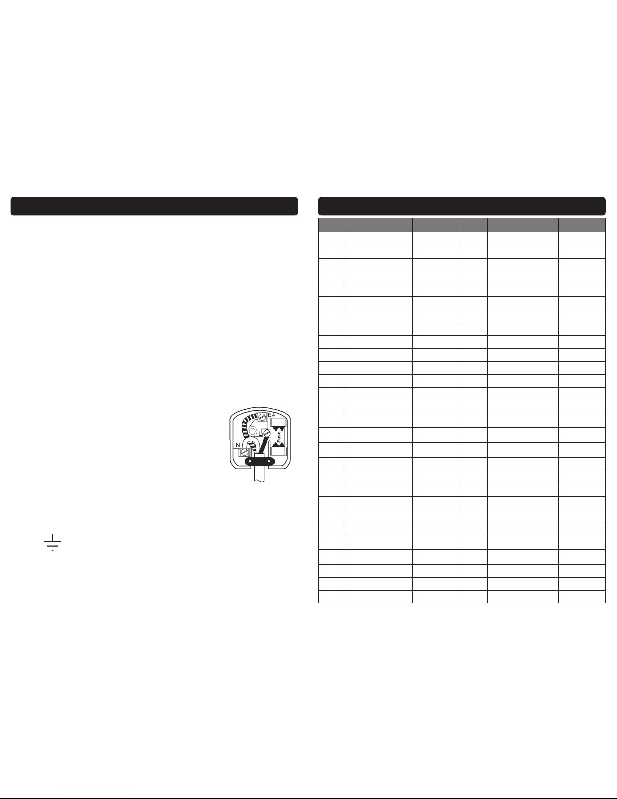
DO NOT ABUSE THE MAINS LEAD: Never pull the mains lead to remove the plug from
the mains socket, or to move the bandsaw from place to place. Keep the mains lead
away from heat, oil and sharp edges. If the mains lead is damaged, it must be re-
placed by the manufacturer or its service agent or a similarly qualified person in order
to avoid unwanted hazards.
ALWAYS check that the belt guard and blade guards are in place, adjusted correctly,
undamaged and firmly attached.
NEVER STAND ON THE BANDSAW: The bandsaw is not designed for this purpose.
DO NOT dismantle, tamper with or modify the bandsaw, as this may be dangerous
and will invalidate the warranty.
SECURE THE WORK-PIECE: Use the vice to hold the work-piece; this frees up both hands
to operate the saw.
REMOVE ADJUSTING KEYS AND WRENCHES: Form a habit of checking to see that keys
and adjusting tools are removed from the bandsaw before every use.
If a problem with the bandsaw is experienced or suspected stop using the bandsaw
immediately and contact your distributor for repair.
Regularly inspect the bandsaw, ensuring that it is in good working order and condi-
tion.
Always ensure that the work area is clean, tidy and free from unrelated materials.
Operate away from flammable objects, materials & surfaces.
Use in a location where accidental contact (particularly by children) is unlikely.
Ensure on/off switches are switched to off position (0) before connecting the mains
lead to the power supply.
Keep the work area clean and clear of possible tripping hazards.
Keep children and unauthorised persons away from the bandsaw, as it has a sharp
blade!
Disconnect from the mains before moving or attempting any cleaning or mainte-

6
SAFETY INSTRUCTIONS….cont
nance.
Keep hands and all other body parts away from the blade.
Turn the bandsaw off and disconnect it from the mains supply when moving from
one location to another.
Never operate the bandsaw without all guards in place.
DO NOT get the bandsaw wet or use in damp or wet locations or areas where there
is condensation.
DO NOT move the bandsaw whilst in operation.
DO NOT remove the blade guard or belt guard whilst the bandsaw is switched on.
DO NOT allow unqualified persons to disassemble the bandsaw for any reason, the
bandsaw must be checked and adjusted etc. by qualified personnel only.
DO NOT use the bandsaw without the blade guard and belt guard closed, as this
could lead to personal injury to you or others!
ALWAYS ensure a blown fuse is replaced with the correct fuse type and rating.
DO NOT place any objects on the safety guard or on the covers at any time.
When not in use, store the bandsaw carefully in a safe, dry, childproof location.
NEVER cover the bandsaw during operation or whilst it cools after operation.
Be aware of moving parts that occur during normal operation of this bandsaw.
NEVER operate the bandsaw with damaged, broken or missing parts, or with any
guards or covers removed.
DO NOT operate the bandsaw or any electrical items with wet hands.
Keep the floor around the machine clean and free of scrap material, oil and grease
etc.
ALWAYS keep the machine guards in place at all times when the machine is in oper-
ation, if removed for maintenance, use extreme caution, always refit the guards im-
mediately after any maintenance.
DO NOT over reach, always maintain a balanced stance so that you do not fall or
lean into any moving parts.
Keep all visitors at a safe distance.
ALWAYS keep hands and fingers away from the blade when in operation.
ALWAYS use the vice to secure your material, never cut any material without using
the vice; this is extremely dangerous!
ALWAYS have the belt guard closed at all times when the machine is in operation,
failure to do this can lead to personal injury.
ALWAYS use adequate roller stands for supporting longer and heavier materials.
ALWAYS use the correct blade, using the correct tpi blade for cutting the material will
make your job easier, and the blade last longer, using the wrong tpi blade will make
a rough cut and will decrease the life of the blade.
NEVER force the blade through the material, this will decrease the life of the blade.
ALWAYS keep the bandsaw as clean as possible and keep blades sharp for best
and safest performance.
WARNING! round bar and tubing have a tendency to roll whilst being cut and can
31
Ref. No. Description SIP Part No. Ref. No. Description SIP Part No.
275. Wave washer M16 WK04-00340 303. Washer M8 WK04-00014
276. Washer M16 WK04-00061 304. Wave washer M8 WK04-00359
277. Rotating sleeve cap WK04-00341 305. Bolt M8x25 WK04-00137
278. Rotating arm WK04-00342 306. Bottom shelf WK04-00360
279. Spring WK04-00343 307. Nut M8 WK04-00015
280. Bolt WK04-00344 308. Washer WK04-00361
281. Nut M10 WK04-00052 309. Bolt M8x16 WK04-00013
282. Bolt support WK04-00345 310. Wheel WK04-00006
283. Bolt M8x20 WK04-00068 311. Axle WK04-00362
284. Lever lock WK04-00346 312. Pin 3x25 WK04-00007
285. Lever lock washer WK04-00347 313. Bolt M8x16 WK04-00013
286. Scale WK04-00348 314. Washer M8 WK04-00014
287. Bolt M10x40 WK04-00056 315. Shaft for hyd. cylinder WK04-00064
288. Nut M10 WK04-00052 316. Nut M12 WK04-00173
289. Bolt M6x25 WK04-00349 317. Bolt M12x60 WK04-00364
290. Seat WK04-00350 318. Coolant tray WK04-00365
291. Rotating arm plate WK04-00351 319. Bolt M6x12 WK04-00038
292. Bolt M8x25 WK04-00137 320. Washer M6 WK04-00011
293. Disc WK04-00352 321. Sleeve WK04-00366
294. Upper shelf WK04-00353 322. Cut off stop WK04-00367
295. Block WK04-00354 323. Cut off stop shaft WK04-00368
296. Nut M8 WK04-00015 N/A. QF1 Breaker WK04-00146
297. Bolt M8x40 WK04-00132 N/A. QF2 Breaker WK04-00148
298. Fixed seat shaft WK04-00355 N/A. QF3 Breaker WK04-00149
299. Fixed seat WK04-00356 N/A. Contactor CN6 WK04-00150
300. Bolt M8x25 WK04-00137 N/A. Thermal relay 5.5-8.5A WK04-00151
301. Washer M8 WK04-00014 N/A. Transformer WK04-00153
302. Base WK04-00357 N/A. Blade guard microswitch WK04-00154
302.1. Base WK04-00358
NOTES
PARTS LIST….cont

30
PARTS LIST….cont
Ref. No. Description SIP Part No. Ref. No. Description SIP Part No.
181. Motor plate holder WK04-00131 246. Bolt M8x30 WK04-00018
182. Bolt M8x40 WK04-00132 247. Washer M8 WK04-00014
183. Washer M8 WK04-00014 248. Bearing 51101 WK04-00320
184. Washer M8 WK04-00014 249. Bearing cover WK04-00321
185. Bolt M8x20 WK04-00068 250. Spring WK04-00322
186. Bolt M8x50 WK04-00133 251. Vice handle WK04-00323
187. Nut M8 WK04-00015 252. Handle knob WK04-00324
188. Motor plate WK04-00134 253. Lead screw WK04-00325
189. Motor WK04-00135 254. Acme nut WK04-00326
190. Bolt M8x25 WK04-00137 255. Vice bed WK04-00327
191. Washer M8 WK04-00014 256. Moving vice jaw WK04-00328
192. Nut M8 WK04-00015 257. Washer M10 WK04-00046
193. Motor key WK04-00138 258. Lever lock WK04-00329
194. Belt guard screw WK04-00139 259. Bolt M10x35 WK04-00045
195. Belt guard WK04-00140 260. Fixed vice jaw WK04-00330
196. Pulley screw M8x10 WK04-00141 261. Washer M8 WK04-00014
197. Worm pulley WK04-00142 262. Bolt M8x30 WK04-00018
198. Pulley screw M8x10 WK04-00141 263. Bolt M10x30 WK04-00331
199. Motor pulley WK04-00143 264. Washer M10 WK04-00046
200. Belt WK04-00144 265. Bolt M8x16 WK04-00013
201. Washer M6 WK04-00011 266. Key 8x100 WK04-00332
202. Bolt M6x12 WK04-00038 267. Bolt M8x25 WK04-00137
239. Handle WK04-00315 268. Roller WK04-00333
240. Nut M10 WK04-00052 269. Rotating disc WK04-00334
241. Handle bracket WK04-00316 270. Bolt M16x65 WK04-00335
242. Bolt M6x12 WK04-00038 271. Bolt M12x16 WK04-00336
243. Pin 5x25 WK04-00317 272. Spring WK04-00337
244. Speed fix block WK04-00318 273. Shaft WK04-00338
245. Speed moving block WK04-00319 274. Rotating sleeve WK04-00339
7
SAFETY INSTRUCTIONS….cont
cause the blade to slip, DO NOT cut such items without clamping or blocking the
material.
DO NOT start the bandsaw until the material is secure and the blade has been low-
ered to just above the material.
NEVER use damaged or deformed bandsaw blades.
ALWAYS secure the material that is too be cut in the vice.
NEVER use the bandsaw with the blade guard or wheel cover removed.
DO NOT use whilst under the influence of drugs, alcohol or other intoxicating medi-
cation.
NEVER start the bandsaw with the blade in contact with the work-piece.
ALWAYS allow the bandsaw to reach full speed before commencing the cutting op-
eration.
NEVER use this bandsaw for any application other than that specified by the manu-
facturer.
Never operate this bandsaw under conditions not approved by the manufacturer.
Before using or servicing your bandsaw, read and understand all instructions. Failure
to follow safety precautions or instructions can cause equipment damage and/or
serious personal injury.
WEAR THE CORRECT CLOTHING. Do not wear loose clothing, neckties, rings, brace-
lets, or other jewellery, which may get caught in moving parts. Non-slip footwear is
recommended. Wear protective hair covering to contain long hair. Roll long sleeves
up above the elbow.
If the bandsaw is used in a place of work all rules and laws etc. relating to the use of
portable electrical appliances should be followed.
Failure to follow the warnings in this manual, may result in personal injury and/or
property damage.
CAUTION: The warnings and cautions mentioned in this user manual can not cover all possible
conditions and situations that may occur. It must be understood by the operator that com-
mon sense and caution are factors which cannot be built into this product, but must be ap-
plied.
When using the saw, particularly during extended periods; ensure the opera-
tor as well as those in the area wear ear protection.
When using the saw always ensure the operator as well as those in the area
wear eye protection.
Some materials have the potential to be highly toxic; always wear a face
mask when operating the saw.

8
ELECTRICAL CONNECTION
WARNING! It is the responsibility of the owner and the operator to read, understand
and comply with the following:
You must check all electrical products, before use, to ensure that they are safe.
You must inspect power cables, plugs, sockets and any other connectors for wear or
damage.
You must ensure that the risk of electric shock is minimised by the installation of appro-
priate safety devices; A residual current circuit Breaker (RCCB) should be incorporated
in the main distribution board. We also recommend that a residual current device
(RCD) is used. It is particularly important to use an RCD with portable products that are
plugged into a supply which is not protected by an RCCB. If in any doubt consult a
qualified electrician.
Connecting to the power supply:
This SIP bandsaw is fitted with a standard 230v ~ 13 amp type plug. Before using the
bandsaw, inspect the mains lead and plug to ensure that neither are damaged. If
any damage is visible have the bandsaw inspected / repaired by a suitably qualified
person. If it is necessary to replace the plug a heavy duty impact resistant plug would
be preferable.
The wires for the plug are coloured in the following way:
Yellow / green Earth
Blue Neutral
Brown Live
As the colours of the wires may not correspond with the markings in your plug, pro-
ceed as follows: The wire which is coloured blue, must be connected to the terminal
marked with N or coloured black. The wire which is coloured brown, must be connect-
ed to the terminal, which is marked L or coloured red. The wire which is coloured yel-
low / green should be connected to the terminal which is coloured the same or
marked
Always secure the wires in the plug terminal carefully and tightly. Secure the cable in
the cord grip carefully.
29
Ref. No. Description SIP Part No. Ref. No. Description SIP Part No.
126.1. Washer M10 WK04-00046 152. Gearbox housing WK04-00110
127. Pin WK04-00088 152.1. Bolt M8x16 WK04-00013
129. Bearing 608ZZ WK04-00090 153. Bearing 6005ZZ WK04-00111
130. Fixed bearing shaft WK04-00091 154. Circlip WK04-00112
131. Eccentric bearing shaft WK04-00092 155. Oil seal 47x25x7 WK04-00113
132. Bearing 608ZZ WK04-00090 156. Seal WK04-00114
133. Washer M8 WK04-00014 157. Worm gear shaft WK04-00115
134. Bolt M5x12 WK04-00093 157.1. Key 6x25 WK04-00116
135. Front plate WK04-00094 158. Circlip WK04-00117
136. Bolt M8x30 WK04-00018 159. Worm gear WK04-00118
137. Right guide holder WK04-00095 160. Gearbox cover gasket WK04-00119
137.1. Left guide holder WK04-00096 161. Gearbox cover WK04-00120
138. Right guide bracket WK04-00097 162. Washer M6 WK04-00011
139. Large washer M10 WK04-00098 163. Bolt M6x20 WK04-00016
140. Bolt M10x40 WK04-00056 164. Oil drain bolt WK04-00121
141. Bolt M5x10 WK04-00099 168. Upper support
hydraulic cylinder WK04-00122
142. Brush holder WK04-00100 169. Washer M8 WK04-00014
143. Brush WK04-00101 170. Bolt M8x30 WK04-00018
144-1. Sleeve A WK04-00102 171. Bolt M4x12 WK04-00123
144-2. Sleeve B WK04-00103 172. Bearing cover WK04-00124
144-3. Sleeve C WK04-00104 173. Circlip WK04-00125
145. Spring WK04-00105 174. Bearing 6003ZZ WK04-00126
146. Bolt M6x6 WK04-00010 175. Oil seal 35x17x7 WK04-00127
147. Switch c/w
emergency stop button WK04-00106 176. Worm sleeve WK04-00128
148. Bolt M10x25 WK04-00107 177. Worm shaft WK04-00129
149. Washer M10 WK04-00046 178. Side support WK04-00130
150. Key 6x25 WK04-00108 179. Washer M6 WK04-00011
151. Bushing WK04-00109 180. Bolt M6x12 WK04-00038
PARTS LIST….cont

28
PARTS LIST
Ref. No. Description SIP Part No. Ref. No. Description SIP Part No.
14. Hydraulic cylinder WK04-00009 100. Bolt M8x20 WK04-00068
25. Filter WK04-00017 101. Large washer M8 WK04-00069
31. Coolant tank WK04-00020 102. Bearing 6203ZZ WK04-00070
32. Hose WK04-00021 103. Idle blade wheel WK04-00071
33. Coolant pump WK04-00022 103.1. Drive blade wheel WK04-00072
34. Bolt M6x16 WK04-00010 104. Blade 07730
35. Hose fitting WK04-00023 105. Idle wheel sleeve WK04-00073
36. Hose clamp WK04-00024 106. Saw bow WK04-00074
37. Hose WK04-00025 107. Blade tension screw WK04-00075
50. End stop microswitch WK04-00037 108. Spring WK04-00076
53. Thumb screw for
cut off stop WK04-00039 109. Plate WK04-00077
75. Bolt M10x40 WK04-00056 110. Washer M6 WK04-00011
76. Nut M10 WK04-00052 111. Bolt M6x16 WK04-00010
77. Bolt M10x35 WK04-00045 112. Idle wheel shaft WK04-00078
78. Pivot arm plate WK04-00057 113. Idle wheel shaft seat WK04-00079
79. Pivot arm WK04-00058 114. Pin 4x20 WK04-00080
80. Bed shaft WK04-00059 115. Moving plate WK04-00081
82. Washer M16 WK04-00061 116. Bolt M8x16 WK04-00013
83. Nut M10 WK04-00052 117. Bolt M8x35 WK04-00082
93. Bolt M10x45 WK04-00065 118. Washer M8 WK04-00014
94. Washer M10 WK04-00046 119. Adjustable bracket WK04-00083
94.1. Nut M10 WK04-00052 120. Adjustable bracket screw WK04-00084
95. Bolt M8x16 WK04-00013 121. Copper pipe WK04-00085
96. Washer M8 WK04-00014 122. Bolt M6x6 WK04-00010
97. Blade guard WK04-00066 123. Copper pipe support WK04-00086
97.1. Wheel cover WK04-00067 124. Coolant tap WK04-00087
98. Bolt M8x16 WK04-00013 125. Bolt M8x30 WK04-00018
99. Washer M8 WK04-00014 126. Nut M10 WK04-00052
9
ELECTRICAL CONNECTION….cont
Warning: Never connect live or neutral wires to the earth terminal of the plug.
Only fit an approved plug with the correct rated fuse. If in doubt consult a
qualified electrician.
Note: Always make sure the mains supply is of the correct voltage and
the correct fuse protection is used. In the event of replacing the fuse al-
ways replace the fuse with the same value as the original.
Note: If an extension lead is necessary in order to reach the mains supply; The
cross section should be checked so that it is of sufficient size so as to reduce
the chances of voltage drops. Always fully unwind the lead during use.
This SIP bandsaw is covered by a 12 month parts and labour warranty covering failure
due to manufacturers defects. This does not cover failure due to misuse or operating
the bandsaw outside the scope of this manual - any claims deemed to be outside
the scope of the warranty may be subject to charges Including, but not limited to
parts, labour and carriage costs.
This guarantee does not cover consumables such as bearings, oil, blade, etc.
In the unlikely event of warranty claims, contact your distributor as soon as possible.
Proof of purchase will be required before any warranty can be honoured.
GUARANTEE
Note: Proof of purchase will be required before any warranty can be hon-
oured.

10
GETTING TO KNOW YOUR BANDSAW
1 2 3 4
5
6
7
8
9
10
1112
13
15
16
16
14
17
18
20
21
22
23
24
19
27
SAW BASE
EXPLODED DIAGRAM….cont

26
EXPLODED DIAGRAM
SAW BOW
11
GETTING TO KNOW YOUR BANDSAW….cont
CONTROL PANEL
Ref. Description Ref. Description
1. Switch 13. Vice base
2. Emergency stop button 14. Tension spring
3. Gearbox 15. Pivot arm
4. Belt / Pulley guard 16. Blade cover
5. Motor 17. Vice stop
6. Right adjustable guide bracket 18. Lever lock
7. Hydraulic Ram 19. Cut off stop (hole)
8. Electrical box 20. Vice hand-wheel
9. Filter 21. Vice assembly
10. Quick vice handle 22. Coolant tap
11. Coolant pump 23. Left adjustable guide bracket
12. Coolant tank 24. Blade tensioning knob
A. Power on light When lit the machine is ready for operation.
B. Coolant pump switch Turns the coolant pump on / off.
C. Start button Turns the machine on.
D. Stop button Turns the machine off.
E. Emergency stop button
Interrupts power to the system and stops the motor,
twist the button until it pops out to bring power back
to the machine.
A B CDE

12
CONTENTS & ACCESORIES
Note: If any of the above are missing or damaged, contact your distribu-
tor immediately.
A. Manual
B. Wheel
C. Cut off stop
D. Cut off stop thumb screw
E. Split pin
F. Cut off stop shaft
G. Axle
B
C
D
E
F
G
A
TECHNICAL SPECIFICATION
Name 8” Swivel Metal Cutting Bandsaw
Part Number 01593
Input Voltage 230v ~ 50Hz
Circular 45˚ 127mm
Circular 0˚ 178mm
Rectangle 45˚ 85 x 140mm
Rectangle 0˚ 178 x 210mm
Blade Speed 22, 33, 45 & 65 mtr/min
Blade Size 2362 x 0.9 x 19mm
Motor Power 1.5HP (1.1kw)
Drive V-belt
Packed Dimensions 1290 x 730 x 1150mm
Net Weight 170kgs
Gross Weight 192kgs
25
WIRING DIAGRAM
Reference Description Specification Reference Description Specification
M1 Main motor 50Hz 1ph KM Contactor CN6 AC24v 50Hz
M2 Coolant pump 230/400v 50Hz 40w FR Heat relay RHM-5N 5.5-8.5A
TC Transformer AC400,230 24v SQ1 Limit switch QKS7 250V 10A
QF1 Current breaker DZ47-63 3P 5A SQ2 Interlocking switch QKS8 250V 10A
QF2 Current breaker DZ47-63 2P 2A SB Start XB2-BE101
QF3 Current breaker DZ47-63 1P 1A SA1 Stop XB2-BE102
TA Switch XB2-BX542 SA2 Start XB2-ED21
EL Indicator light XB2-BVD3

24
TROUBLESHOOTING
Symptom Possible cause Solution
Unusual wear on side or
back of blade.
1. Blade guides are worn.
2. Blade guides not properly adjusted.
3. Blade guide brackets are loose.
1. Replace blade guides.
2. Adjust blade guides.
3. Tighten blade guide brackets.
Excessive blade breakage
and teeth ripping from the
blade.
1. Material is loose in the vice.
2. Incorrect speed or feed.
3. Blade is too coarse.
4. Incorrect blade tension.
5. Blade is in contact with material before
bandsaw is started.
6. Blade is rubbing on the wheel flange.
7. Blade guides are misaligned.
8. Blade is too thick.
9. Bad weld on blade
1. Clamp the material securely.
2. Adjust speed or feed.
3. Use correct blade for material.
4. Adjust blade tension so that it does not
slip on the wheel.
5. Place the blade in contact with the mate-
rial only after the saw has started.
6. Adjust the blade tracking.
7. Adjust blade guide alignment.
8. Use correct thickness blade.
9. Re-weld or replace blade.
Motor overheating.
1. Blade tension too high.
2. Drive belt tension too high.
3. Blade too coarse or too fine.
4. Gears need lubrication.
5. Blade is binding in the cut.
1. Reduce blade tension.
2. Reduce belt tension.
3. Use a blade designed for the material.
4. Lubricate the gears.
5. Decrease feed and speed.
Blade is twisting. 1. Blade tension is too high.
2. Blade is binding in the cut.
1. Decrease blade tension.
2. Decrease feed pressure.
Bad, rough or crooked cuts.
1. Blade is too coarse.
2. Blade guide assembly is loose.
3. Blade guides are spaced out too far.
4. Incorrect speed.
5. Blade is blunt.
6. Inadequate blade tension.
7. Blade guide bearings not properly adjust-
ed.
8. Feed pressure too much.
1. Use a finer blade.
2. Tighten the guide assembly.
3. Move guides closer to the material.
4. Adjust speed.
5. Replace the blade.
6. Increase blade tension a little at a time.
7. Adjust blade guide bearings.
8. Reduce feed pressure by increasing the
spring tension on the arm.
Premature blade dulling.
1. Blade tpi is too high.
2. Incorrect speed - too fast.
3. Inadequate feed pressure.
4. Hard spots or scale on the material.
5. Blade installed backwards.
6. Insufficient blade tension.
7. Work hardened material especially stain-
less.
1. Replace with a lower tpi blade.
2. Reduce speed.
3. Increase feed pressure by unscrewing
tension bar. This will decrease the spring
tension on the arm.
4. Reduce speed, increase feed pressure.
5. Remove blade, twist inside out and rein-
stall.
6. Increase blade tension.
7. Increase feed pressure by reducing spring
pressure.
13
ASSEMBLY INSTRUCTIONS
Danger / Caution: At least 2 persons are required to remove this bandsaw from it`s
packaging it is extremely heavy! Failing to follow this can have serious conse-
quences and could lead to personal injury and/or the possibility of damage.
FITTING THE WHEELS
FITTING THE CUT OFF STOP
UNPACKING
1. Remove the bandsaw from the packaging, check the bandsaw for any signs of
damage or missing items prior to assembling.
2. Unbolt the bandsaw from the wooden base.
3. Put two pieces of sturdy wood on the floor, so that the bandsaw can be low-
ered onto it as a temporary measure.
4. Use proper lifting equipment to move the bandsaw from the wooden base and
onto the blocks of wood.
1. Slide one wheel (B) onto the axle (G), secure with a split pin (E).
2. Now push the axle through the pre-drilled holes at the corner of the stand.
3. Fit the other wheel onto the opposite end of the axle and secure with the split
pin.
4. Repeat process for the opposite end.
5. Use the lifting equipment to raise the bandsaw slightly, so you can remove the
wooden blocks.
6. Lower the bandsaw onto the ground, you are now ready to move the bandsaw
into your desired location.
1. Slide the cut off stop shaft (F) through the cut off stop hole (page 10, ref.19) on
the front of the casting.
2. Slide the cut off stop (C) onto the shaft (F), secure using the thumb screw (D).
3. The cut off stop is now ready to be used.
CLEANING THE SUFACES PRIOR TO OPERATION
Before using the bandsaw it is best to clean the rust protected surfaces using kerosene
(paraffin), diesel oil or mild solvent. Never use cellulose based solvents such as paint
Note: If any items are missing or damaged, DO NOT use the machine,
contact your distributor immediately.

14
ASSEMBLY INSTRUCTIONS….cont
A
B
B
Fig.1
65
Motor
45
33
22
Blade Speed m/min Fig.2
SETTING THE BLADE SPEED
Before the bandsaw can be used the transit bolt and
bracket must be removed; this is situated at the end of
the saw bow and bed (see right picture). Once the
bracket is removed refit the head stop bolt and adjust
it’s height so as to prevent excessive pressure on the
end of cut microswitch.
Remove
REMOVING THE TRANSIT BOLT
OPERATING INSTRUCTIONS
thinner or lacquer thinner as these will damage the painted surfaces.
1. Prior to changing the blade speed ensure the mains lead is disconnected.
2. Unscrew and remove the belt guard screw and lift up the cover, this will allow
access to the belt so it can be adjusted.
3. Loosen the motor plate lock bolt (Fig.1,A).
4. Loosen the motor slide bolts (Fig.1,B), you
should now be able to push the motor inwards
to slacken the belt.
5. Move the belt to the desired speed (Fig.2).
6. Once the belt has been set to the desired speed, re-tension the belt by tighten-
ing the bolts.
7. Close the belt guard and secure with the screw.
See the table on page 15 for a guide to approximate blade speed for different mate-
rials.
23
MAINTENANCE INSTRUCTIONS….cont
Note: The outer bearing shaft is eccentric and is the one to adjust, the
inner bearing shaft is fixed and can not be adjusted.
Note: Never attempt to adjust the blade guide bearings whilst the ma-
chine is running, ALWAYS disconnect from the mains supply before pro-
ceeding.
1. Raise the saw bow to the vertical position and lock it by turning the hydraulic
cylinder tap to the off position.
2. Remove the two screws holding the bearing guard plate onto the lower eccen-
tric shaft.
3. Loosen the nut (Fig.15,A) holding the eccentric shaft in position.
4. With a spanner turn the eccentric shaft (Fig.15,B) until there is a gap of about
0.03mm (0.001”), you should just be able to slide a piece of paper between
the gap.
5. Once the eccentric shaft has been adjust-
ed, retighten the nut (A) and screw the plate
back on.
6. Repeat steps 3-5 for the upper eccentric
shaft.
Fig.15
A B
GENERAL MAINTENANCE
Do not use compressed air to clean the bandsaw, this can cause metal fillings
to go into the guide bearings and other parts of the bandsaw.
Always remove the metal fillings from the blade guides after use.
Wipe the bandsaw down with a dry cloth.
Check the guide bearings regularly making sure they are clean and correctly
adjusted.
Always check to make sure the wire brush properly adjusted and cleaned.
Always disconnect from the mains supply before carrying out any mainte-
nance.

22
MAINTENANCE INSTRUCTIONS….cont
SETTING THE BLADE SQUARE TO THE BED AT 0˚
BLADE GUIDE BEARING ADJUSTMENT
Note: The correct guide bearing adjustment is very important, this will
make the blade run smoother and evenly without any snagging or twisting
whilst the blade is running. It will also prolong the blade life.
ADJUSTING THE BOW WEIGHT
The bow weight is one of the most important adjustments on the saw. If the bow
weight is set incorrectly then expect poor performance, crooked cuts, teeth stripping
from the blade, stalling and the blade coming off the blade wheels. The hydraulic
cylinder feed rate will not compensate for improper bow weight. A new machine will
have the bow weight pre-set, if you need to adjust the bow weight then follow the
steps below.
1. Disconnect the mains from the supply.
2. Ensure the bow is at its lowest position.
3. Turn the hydraulic cylinder knob anti-clockwise
until it stops.
4. Place a scale on the Blade tensioning knob, lift
the saw bow up, the scale should read be-
tween 5-6kgs.
5. If it doesn't then adjust the tension nut (Fig.14)
until it reaches between 5-6kgs. Fig.14
Tension nut
1. Ensure the bow is at its lowest position.
2. Disconnect from the mains supply.
3. Place an engineer`s set square onto the
bed and touching the blade (Fig.13).
4. If any adjustment is needed then loosen the
two cap head bolts (Fig.13).
5. Rotate both blade guides in the required
direction until the blade makes contact with
the set square along the entire width of the
blade.
6. Once set correctly, retighten both cap
head bolts.
7. The blade guide bearings may need to ad-
justed. Cap head bolts
Set square
Fig.13
15
OPERATING INSTRUCTIONS….cont
Material
Speed
M/Min
(FPM)
Material
Speed
M/Min
(FPM)
Material
Speed
M/Min
(FPM)
Material
Speed
M/Min
(FPM)
Carbon
steel
60 - 108
(196 - 354)
Tool steel
62
(203)
Alloy steel
34 - 98
(111 - 321)
Free
machining
stainless steel
46 - 62
(150 - 203)
Steel
section
54 - 67
(180 - 220)
High speed
tool steel
23 - 36
(75 - 118)
Mild steel
75
(246)
Gray cast iron
33 - 75
(108 - 255)
Thin tube
54 - 67
(180 - 220)
Cold work
tool steel
95 - 213
(29 - 65)
Water
hard
tool steel
242
(74)
Ductile
austenitic cast
iron
65 - 85
(20 - 26)
Aluminium
alloy
67 - 163
(220 - 534)
Hot work
tool steel
62
(203)
Stainless
steel
26
(85)
Malleable cast
iron
98
(321)
Copper
alloy
70 - 147
(229 - 482)
Oil
hardening
tool steel
62 - 65
(203 - 213
Cold
rolled
stainless
Steel
26 - 62
(85 - 203)
Note: The above table is an approximate guide reference only, various
factors mean some materials may require different speeds to the ones
quoted.

16
OPERATING INSTRUCTIONS….cont
OPERATING THE VICE
Setting The Vice For Maximum Width Cutting at 0˚:
1. Raise the saw bow so it is clear of
the vice assembly.
2. Remove the 4 cap head bolts
(Fig.3), and loosen both rollers.
Note: The angle is set by moving the saw bow, you can not set the angle
by the vice assembly.
Rollers
Fig.3
Cap head bolt
Cap
head
bolts
3. Slide the vice assembly forward, so that
the two holes on the vice sit over the two
threaded holes on the vice base (Fig.4).
Fig.4
4. Re-fit only 3 cap head bolts (Fig.5) re-
tighten the rollers.
5. Loosen the lever lock and put the vice
stop into position (Fig.5).
6. Move the saw bow to 0˚ on the vice
scale.
7. Tighten the lever lock.
8. Slide the right adjustable guide bracket
to the left of the vice jaw.
9. The vice is now set up for maximum width
cutting at 0˚, please note that on this po-
sition you can not do angled cuts.
Fig.5
Cap head bolt
Lever lock
Vice stop
21
MAINTENANCE INSTRUCTIONS….cont
Blade tension is important for the correct operation of the bandsaw; the blade tension
should be set between 700-900kgs.
To set the blade correctly without using a blade tension gauge, take the following
steps.
1. Disconnect the bandsaw from the mains supply.
2. Open the blade guard by sliding up and removing the removable cover
(Fig.10)
3. Remove the two thumbscrews screws on the blade guard (Fig.11).
4. Tension the blade slightly to take any slack off the blade.
5. Turn the Blade tensioning knob in a clockwise direction, one and a half turns or
two full turns, this will equal approximately 800kgs of blade tension.
6. Close the blade guard etc. and connect to the mains supply.
7. Run the bandsaw between 2-3 minutes so the blade can seat correctly.
8. Stop the bandsaw and disconnect from the mains supply.
9. Open the blade guard and loosen the blade until it just begins to slacken.
10. Tighten the blade so it becomes straight between the blade wheels, and all the
slackness has gone.
11. Turn the Blade tensioning knob approximately two full turns, this should now be
tensioned correctly.
Fig.10
Remove
Fig.11 Fig.12
B
A

20
MAINTENANCE INSTRUCTIONS
CHAINGING THE BLADE
Caution: Before carrying out any maintenance always disconnect the
bandsaw from the mains supply.
Caution: We strongly advise wearing gloves for protection when changing
blades, blades are sharp and dangerous and can cause personal injury.
Note: The bandsaw was designed to use a 2362 x 0.9 x 19mm size blade,
always use this size blade.
1. Disconnect from the mains supply.
2. Raise the saw bow into a vertical position.
3. Open the blade guard by sliding up and removing the removable cover
(Fig.10).
4. Remove the two thumbscrews on the blade guard (Fig.11)
5. Take the tension off the blade by turning the Blade tensioning knob anti-
clockwise.
6. Remove the wire brush and the upper blade guard (Fig.12, A & B).
7. Ease the blade from the lower wheel first and then from the top wheel, carefully
remove it from the blade guide bearings.
8. Fit the new blade through the blade guide bearings first, then ease it onto the
lower wheel then onto the top wheel.
9. Use both hands to work the blade onto both wheels.
10. Put a small amount of tension on the blade (see tensioning the blade).
11. Once done reattach the blade guards etc.
12. The blade will need to be fully tensioned see below on how to do this.
TENSIONING THE BLADE
Caution: DO NOT over tension the blade as this will warp and stretch the
blade.
Danger / Caution: Blades are sharp use extra care when removing, in-
stalling or handling.
17
OPERATING INSTRUCTIONS….cont
Note: When the vice assembly is set at the angle cutting position you will
lose the maximum width cutting capacity.
Setting The Vice For Angled Cuts:
The bandsaw should be set up ready for angle cutting, if not use the below steps to
set it up correctly.
1. Raise the saw bow so it is clear of the vice assembly.
2. Remove the 3 cap head bolts (Fig.5) and loosen both rollers (Fig.3).
3. Slide the vice assembly backwards, so that all 4 holes on the vice and the vice
base sit over each over.
4. Fit the 4 cap head bolts and tighten (Fig.3).
5. Retighten both rollers.
6. The bandsaw is now ready to cut your material at different angles.
Quick vice handle
Vice hand-wheel
Fig.6
1. Select the desired position and angle you
wish to cut at and adjust the vice accordingly.
2. Ensure the lever lock (Fig.5) is tightened.
3. Loosen the vice by turning the vice hand-
wheel (Fig.6) anti-clockwise.
4. Place the material to be cut between the two
vice jaws, and retighten the vice hand-wheel
by turning it clockwise, so the vice jaws sit
against the material.
5. Push the quick vice handle (Fig.6) down to
secure the vice jaws.
6. The material is now secure and ready to be
cut.
Using The Vice:

18
OPERATING INSTRUCTIONS….cont
Fig.9
B
A
The hydraulic cylinder has an adjustable rate
of descent; it can be adjusted by turning the
knob (Fig.9,A) clockwise to slow down the
rate, or anti-clockwise to speed up the rate
of decent. The bow can be stopped in any
position by turning the tap (Fig.9,B). When
the tap is at 90˚ to the cylinder the flow will
stop and the bow will stop descending.
HYDRAULIC CYLINDER ADJUSTMENT
1. Slide the coolant tank out from the rear of the
bandsaw (Fig.7).
2. Make sure the filter is fitted and fill with fresh
coolant.
3. Slide the coolant tank back onto the bandsaw
panel, making sure that the coolant hose is
situated over the filter.
4. Open the coolant tap (Page 10, ref. 22).
5. Turn the coolant switch on the control panel
to on (I).
6. The coolant will start to pump once the start
button is pressed and the saw starts to run.
Fig.7
USING THE COOLANT PUMP
1. Disconnect from the mains supply.
2. Loosen the knob (Fig.8,A), so that the
left adjustable guide bracket (Fig.8,B)
can be moved closer to your material.
3. Loosen the bolt (Fig.8,D) and slide the
right adjustable guide bracket (Fig.8,C)
closer to your material.
4. Once adjusted retighten the knob (A)
and bolt (D).
ADJUSTING THE BLADE GUIDES
Note: We recommend the use of water soluble coolant, this will prolong
the blade life and make the cut more efficient.
D
A
Fig.8
CB
19
OPERATING INSTRUCTIONS….cont
1. Disconnect the bandsaw from the mains supply.
2. Set the blade speed to suit the material that is to be cut (see page 14 setting
the blade speed).
3. Raise the saw bow to a vertical position.
4. Adjust the cut length stop to your desired position (if required).
5. Set the vice angle to your desired position.
6. Open the vice and insert the material to be cut then close the vice to secure.
7. Move the two adjustable blade guides closer to the material, but make sure
they don't foul against it or the saw.
8. Adjust the rate of descent of the arm as described on page 18 so that it is
creeping slowly down towards the material, shut off the hydraulic cylinder when
the blade gets close to the material; do not start cutting on a sharp edge file it
off first.
Caution: Never remove the material when the bandsaw is still running, al-
ways switch the machine off before attempting to remove the material,
failure to do this could lead to serious personal injury.
Caution: Never start the bandsaw with the blade in contact with the work-
piece. Allow the saw to reach full speed before commencing cut.
CUTTING WITH THE BANDSAW
Danger: Before attempting to cut always make sure all covers are on and
secure.
Note: The harder the material to be cut the slower the speed should be.
Danger: Do not turn the machine on until the material is secured and the
blade has been lowered just above the material.
9. Plug in to the mains supply and turn the coolant pump on.
10. Start the saw.
11. To bring the blade in to contact with the material to be cut, open the tap on
the hydraulic cylinder, if the blade jams then immediately turn the bandsaw off
and refer to the troubleshooting guide on page 24.
12. Once the cut is complete, the saw should automatically stop.
Table of contents
Other SIP Saw manuals
Popular Saw manuals by other brands

Bosch
Bosch GKS 160 Professional operating instructions

Dolmar
Dolmar PC-6212 HappyStart Service manual

MQ Multiquip
MQ Multiquip MP1H Operation and parts manual

King Industrial
King Industrial KC-1802FXB instruction manual

Scheppach
Scheppach HM216 Translation from the original instruction manual

Bosch
Bosch 3924B-24 Operating/safety instructions