pfa
400
400
____
400
----
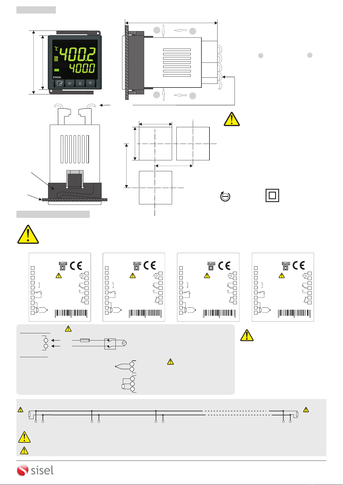
No communication with sensor.
(Sensor and/or cable broken or
not connected)
ERROR MESSAGES
Temperature value is higher
than scale.
Temperature value is lower
than scale.
C h a n g e s t o t h i s
parameter may cause
s o m e p a r a m e t e r
values to change.
inp.t. = Input Type selection.
Pt.0 = PT100 - Decimal,
Pt. = PT100 Non-decimal,
J.0 = J Type - Decimal,
j = J Non-decimal,
k.0 = K Type - Decimal,
k = K Non-decimal,
L.0 = L Type - Decimal,
L = L Non-decimal,
t.0 = T Type - Decimal,
Input Type Selection Chart
t = T Type,
s = S Type ,
r = R Type
C.s.Lo.
-30
C.s.Hi.
600
C. pb
4.0
C. ti
4.0
C. td
1.00
C.P.St.
0
C.Hys
2
C. Ct.
1
C.typ
HEAt
s.s.t.s.
0
C.E.p.s.
0
C.EC.t.
E.PS.
Con.o.
Co.sc.
p.yEs
a.1..sc.
p.yEs
a.2.sc.
p.yEs
Cn.sC.
p.yEs
S.t.sc.
p.yEs
inp.t.
J
Unit
°C
fltr.
20
C.o.sE
C-A2
offs.
0
d.Adr.
1
baud
9.60
d.in.C.
nonE
F.kE.C.
nonE
A2.S.L
-30
A2.S.H
600
A2.HY
2
A2.tP
INDE.
A2.St.
hi.
A2.Er.
ON
S.Cod.
0
s.t.us.
Pid.t.
25
s.tun.
s.t.us.
Al1.o. Al2.o. Conf.. s.tun. SECU.
4/4
A
A1
A2
A1
A2
A3
B
B3
B3
B2
A1.S.L
-30
A1.S.H
600
A1.HY
2
A1.tP.
INDE.
A1.St.
Hi.
A1.Er.
ON
A1.PB
0.0
A1.ti
0.0
A1.td
0
A1.Ct
1
A1.ps
0
A1.Ep
0
B1
B1
B2
B3
B3
B1
B2
B3
CD
D1
D1
D1
D2
E F
A2
A2
A2
A2
A3
If co.SE parameter is
different from C-A2 , this
menu can be displayed in
SSR Out devices.
Alternatively, by pressing key "Running Mode" is entered and by pressing both keys at once, settings automatically
saved and device returns to the "Running Mode" (to the home screen).
During in "Programming Mode", if no key is pressed for 20 sec, settings automatically saved and device returns to the "Running Mode" (to the home
screen).
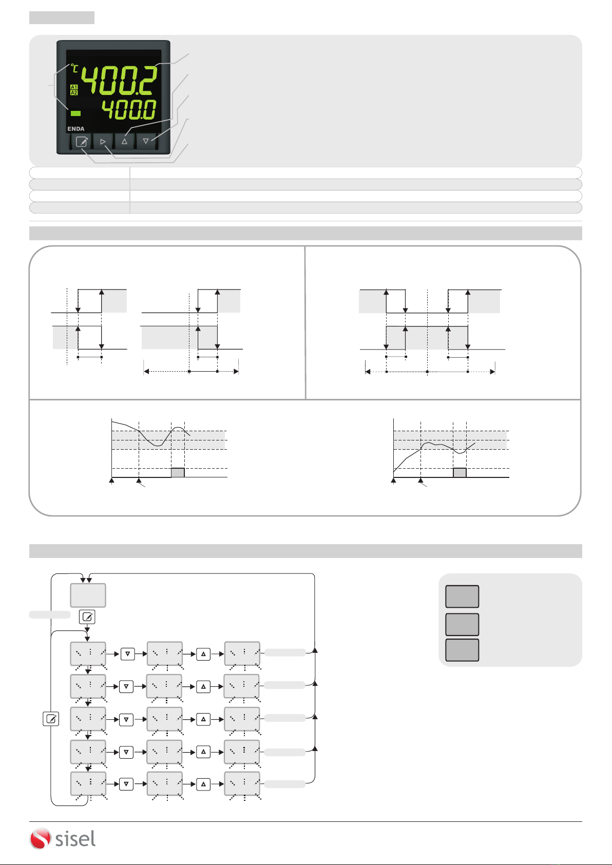
RUNNING MODE
d.lth
10
400
25
If key is pressed while holding key, the "Programming Mode" is entered.
ENTERING TO PROGRAMMING MODE
C.s.lo. = Lower limit for C/A1
Output control, setpoint value.
Can be adjusted between 0 and
C.s.Hi.
C.s.Hi. = Upper limit for C/A1
Output Control, setpoint value.
Can be adjusted between C.s.Lo. and
Upper scale value.
C. Pb = Proportional band value
for C/A1 Output.
Can be adjusted between 0.0% and
100.0.% If C.Pb parameter set to
0.0%, On-Off control will be accepted.
C.Hys = Hysteresis value for C/A1
Output.
Can be adjusted between between
1 and 50 °C.°C
C. ti = Integral value for C/A1
Output.
Can be adjusted between 0.0 and
100.0 minutes. If C. ti parameter
set to 0.0, integral will be disabled.
C. td = C/A1 Output Derivative
value.
Asjustable between 0.00 and 25.00
minutes. If C. td parameter set to
0.0 , derivative will be disabled.
C. Ct. = C/A1 Output periodic time
duration.
Adjustable between 1 and 250
seconds.
C.p.st = C/A2 output power
percentage at C/A1 set value.
Can be adjusted between 0% and
100%.
C.E.C,t. = Control type selection for
sensor failures.
If E.PS selected, controlling will be
performed to according to C.E.P.S.
proportional control parameter.
If Auto is selected, controlling will be
performed to last recorded set value
percentage before probe failure.
C.E.P.s. = C/A1 Output power
percent selection on probe failure.
Can be adjusted between %0 and
%100. If C.Pb set to 0.0 (On/Off
Control) and C.E.P.S. set to 0 , output
will be OFF, on failure. If C.E.P.S. set to
different value from 0 , output will be
ON, in case of failure.
S.S.t.S. = Soft start timer set value.
This parameter determines how many
minutes will be reached to the setpoint
value on power-up.
Can be adjusted between 0 and 250
minutes. If set to 0, the soft start
feature will be canceled and the
setpoint value will be reached
maximum speed.
C.typ. = Output controlling type
selection
HEAt. = Heating control can be
performed.
CooL = Cooling control can be
performed.
a1.s.l =
Can be adjusted between 0 and
Alarm1 set value lower
limit.
A1.S.H parameter value.
a1.s.H = Alarm1 set value upper
limit.
Can be adjusted between A1.S,L and
upper scale value.
a1.Hy = Hysteresis of the Alarm2
output.
Can be adjusted between 1 and 50°C.
A1.tp = Alarm1 types.
Six alarm types can be selected.
indE. = Independent alarm
dE. = Deviation alarm
bAnd = Band alarm
bAn.i = Band with inhibition
in.Co. =
rE.Co =
A1 output independent
cooling control
A1 output relative cooling
control
A1s. t. = Status selection for
Alarm1 Output
If Hi is selected, A1 output is above
the Alarm1 set value ; ON. If lo is
selected, A1 Output is above the
Alarm1 set value ; OFF.
A1.Er. = Alarm1 condition
selection on probe failure
on = A1 Output is ON, in case of
probe failure.
off = A1 Output is OFF, in case of
probe failure.
A1.Pb = A1 Output, proportional
band value.
Can be adjusted between 0% and
100%.
If A1.Pb Parameter set to %0, On-
Off control will be accepted.
A1.ti =
If A1.ti parameter set to 0.0,
integral will be disabled.
A1 Output, integral value.
Can be adjusted between 0.0 and
100.0 minute.
A1.td =
Can be adjusted between 0.00 and
25.00 minutes.
If A1.td parameter set to 0.00,
devirative will be disabled.
A1 output derivative
value.
A1.Ct =
Can be adjusted between 1 and 250
seconds.
A1 Output Period Time.
A1.PS = A1 o u t p u t power
percentage at A1 set value.
Can be adjusted between 0% and
100%.
A1.EP. = A1 Output power percent
selection on probe failure.
Can be adjusted between 0% and
100%.
a2.s.l =
Can be adjusted between 0 and
Alarm2 set value lower
limit.
A2.S.H parameter value.
a2.s.H = Alarm2 set value upper
limit.
Can be adjusted between A2.S,L
and upper scale value.
a2.Hy = Hysteresis of the Alarm2
output.
Can be adjusted between 1 and 50
A2.tp = Alarm2 types.
Four alarm types can be selected.
indE. = Independent alarm
dE. = Deviation alarm
bAnd = Band alarm
bAn.i = Band with inhibition
A2s. t. = Status selection for
Alarm2 Output
If Hi is selected, A2 output is
above the Alarm2 set value ; ON. If
lo is selected, A2 Output is above
the Alarm2 set value ; OFF.
A2.Er. = Alarm2 condition
selection on probe failure
on = A2 Output is ON, in case of
probe failure.
off = A2 Output is OFF, in case
of probe failure.
inp.t. = Input Type Selection.
Please see “Input Type
Selection Table” for details at
the right side of this page.
Unit = Temperature
Unit Selection.
°C = °C / °F = °F
fLtr. = Coefficient of Digital Filter.
Provides to filter for displayed value.
Adjustable between 1 and 200. If this
parameter set to 1, digital filter runs
quickly. If the parameter is set to 200,
filter runs slowly. This parameter value
shouldbe increased in interference
environments.
C.o.sE =
C-A2 =
SSR =
Control output selection.
C/A2 (Relay) output
selection.
SSR output selection.
oFFS. =
The offset value is added to the
measurement value. This feature is
used to eliminate errors that may occur
due to the distance from the measuring
probe to the measuring point.
Can be adjusted between -99 and
100°C. Default value is 0.
Offset Value.
D.aDr. =RS485 Connection Address.
Can be adjusted between 1 and 247.
baud =
Can be adjusted to off, 2.40, 4.80,
9.60, 19.20 and 38.40.
ModBus Baud Rate for
RS485
d.in.C. = Digital input setting
parameter.
nonE = Digital input is closed.
C2.S.A. = if digital input is activated, 2nd
set value is used.
manu. = Manual mode start in case of
digital outputs are active and rational
output generated according to period
value in C.Ct p a remeter and
percentage value in m.SEtparameter.
dSP.o. = If the digital input is activated,
only temperature value will be indicated.
F.kE.C. = Function key setting
parameter.
nonE = Function key is OFF.
C2.S.A. = 2nd. set value can be used
by using function key.
manu. = Manual mode can be
accessed by using function key.
dSP.o. = Temperature value will be
indicated by using function key.
d.lth = Display Brightness
Can be adjusted between 1 and 20.
s.t.us. = Self tune Control Parameter.
If keys are pressed together, main
screen displayed and if the temperature is not
high, pid.t. message flashes on display and
the self tune process starts automatically. If the
initial temperature is higher to self-tune,
tE.hi. message appears and waits until the
temperature goes down. Then Pid.t.
message appears and self tune procedure
starts automatically. After the self tune
procedure, C.Pb , Ct , C.dt and C.Ct. values
are stored in memory and "Running mode"
(main screen) is entered. After the successful
self tune completion, S.tun. menu will be
removed automatically. In order to re-tune,
s.t.sc. parameter should be set to p.yEs in
SECU menu.
STOPPING SELF TUNE
When the self-tune operation needs to be
terminated,“Programming Mode"
should be entered by using keys
and S.tun menu should be selected.
By using key, S.t.uS parameter is
selected and self-tune process can be
terminated by pressing with together
keys.
Cosc. =
CoN.o
nonE =
P.yEs =
P. no =
Security Access Level for
Parameter.
Menu invisible.
Modification can be done.
Only visible.
a.1.sc. = Security Access Level for
al1.o. Parameter.
nonE =
P.yEs =
P. no = Only visible.
Menu invisible.
Modification can be done.
a.2.sc. = Security Access Level for
al2..o. Parameter.
nonE =
P.yEs =
P. no = Only visible.
Menu invisible.
Modification can be done.
Cn.sC. = Security Access Level for
Conf. Parameter.
nonE =
P.yEs =
P. no = Only visible.
Pno = Menu visible only.
Menu invisible.
Modification can be done.
S.t.Sc.. = Security Access Level for
S.tun... Parameter.
nonE =
P.yEs =
Menu invisible.
Modification can be done.
S.Cod = Security menu access code.
To accessing security menu, 430 should
be entered.
While code 0 (, by
held down the key and by pressing
key for 4 seconds, message
appears and default mode is entered.
S.Cod S.Cod = 0 )
dEfP
A1.td
0
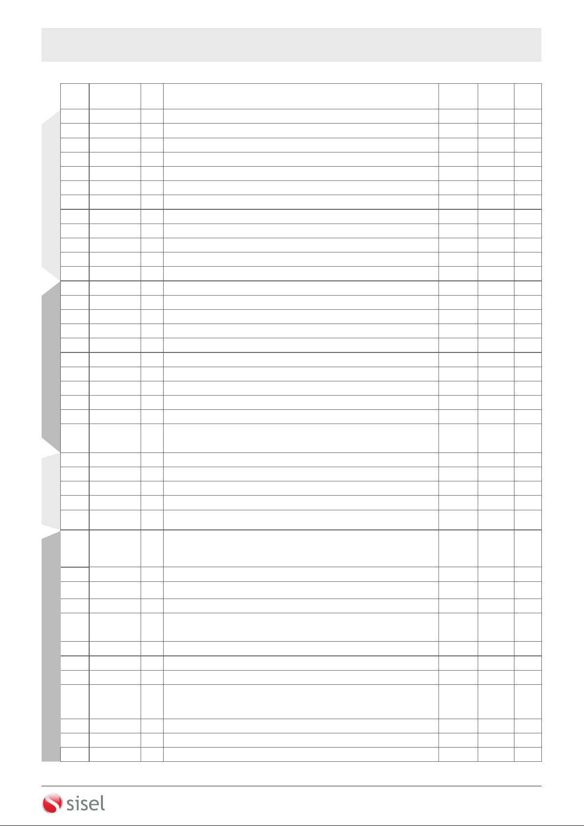
Info r ma tion trac k in g
m e t h o d a b o u t t h e
parameters is as follows.
ABCD
A1
A2
A3
On the device screens
shown on this page ;
- First line indicates the
parameter name,
- Second line indicates the
current parameter's value.
At the same time, the value
shown in the second line is
the default value of the
device.
Parameter name.
Parameter value
(default value).
ANNOTATIONS
Changes to this parameter may cause
some parameter values to change.
This parameter availble in
RS485-Modbus devices only.
Please see ET4430 Modbus
Address Map and Connection
Diagram Guide for Modbus
feature.
C.HyS.
6
C.HyS.
5
C.HyS.
6
C.HyS.
6
If key is pressed and held 0.6 seconds, the value of the selected
parameter changes rapidly. If waited enough, the value increases
100 at each step. After 1 second following the release of the key,
initial condition is returned. The same procedure is valid for the
decrement key.
When holding key, selected parameter flashes and desired
value can be adjusted by using keys.
Parameter Setting Diagram
A1t.P
inC.o. or rEC.o.
Parameter can not be displayed
if is selected.
A1t.P
inC.o. or rEC.o.
Parameter will be activated
if is selected.
This parameter will be activated if the
A1.tp parameter set to in.Co. or
rE.Co. and if the A1.Pb parameter is
different from “0”
This parameter will be activated if the
C.Pb parameter set to “0”.
This parameter will be activated if the
C.Pb parameter different from “0”.
This parameter will be activated if
the C.Pb parameter set to “0” or
C.E.Ct set to E.P.S.
ET4430-EN-01-190116
ENDA ET4430 PROGRAMMING DIAGRAM
SİSEL MÜHENDİSLİK ELEKTRONİK SAN. VE TİC. A.Ş.
Şerifali Mah. Y.Dudullu 34775
ÜMRANİYE/İSTANBUL-TURKEY
Tel : +90 216 499 46 64 Pbx. Fax : +90 216 365 74 01
url : www.enda.com.tr
Barbaros Cad. No:18
D2
D2