SK MEGAPOD SA17-SK Operator's manual

USER INSTRUCTION MANUAL
MEGAPOD
SA17-SK
This instruction manual
applies to the following models:
ANSI Z359.1-2007

Note: The user is advised to keep the user instructions document for the life of the product.
Do not skip this instruction manual. Read the instruction manual carefully before using the equipment. If failed in doing so it may
cause serious Injury or Death.
Manufacturer : SAFE KEEPER, 314 E. CANAL ST. MULBERRY, FL 33860
Certication Body : SATRA Technology Europe Ltd, Bracetown Business Park, Clonee,
Dublin D15 YN2P Ireland (Notied Body 2777)
Ongoing Assessment Body : SGS United Kingdom Ltd., Unit 202B, Worle Parkway,
Weston-super-Mare, BS22 6WA, UNITED KINGDOM.
(Notied Body 0120)
This manual must be read and understood in its entirety and used as part of fall protection training program as required by OSHA or any state
regularity agency. These instructions are intended to meet the manufacturer instructions as required by ANSI Z 359.1-2007 and OSHA . The
user must fully understand the proper equipment use and limitations.
1. GENERAL REQUIREMENTS, WARNINGS AND LIMITATIONS: The Equipment is designed for use as a part of a personal fall protection
system. Components must not be used for any other operation other than that which it has been designed and approved. Fall Arrest
system are designed to comply with OSHA. Fall Restraint System must be designed by a Qualied Person, and must be installed and
used under the supervision of a competent person.
ŸAll authorized persons/users must refer the regulations governing occupational safety, as well as applicable ANSI or CSA
standards. Please refer to product labeling for information on specic OSHA regulations, and ANSI and CSA standards met by
product.
Ÿ Consult a doctor if there is any reason to doubt a user's ability to withstand and safely absorb fall arrest forces. Age, tness, health
conditions can seriously affect the worker a fall occur. Pregnant Women and minors should not use this equipment.
ŸProper precautions should always be taken to remove any obstructions, debris, material, or other recognized hazards from the
work area that could cause injuries or interfere with the operation of the system. All equipment must be inspected before each use
according to the manufacturer's instructions. All equipment should be inspected by a qualied person on a regular basis.
ŸTo minimize the potential for accidental disengagement, a competent person must ensure system compatibility.
ŸEquipment must not be altered in any way. Repairs must be performed only by the Manufacturer, or persons or entities authorized
in writing by the manufacturer.
ŸAny product exhibiting deformities, unusual wear, or deterioration must be immediately discarded. Any equipment subject to a
fall must be removed from service. The authorized person/user shall have a rescue plan and the means at hand to implement it
when using this equipment.
ŸNever use fall protection equipment for purposes other than those for which it was designed. Fall protection equipment should
never be used for towing or hoisting.
ŸAll synthetic material must be protected from slag, hot sparks, open ames, or other heat sources. The use of heat resistant
materials is recommended in these applications.
ŸNever use natural materials (manila, cotton,etc.) as part of a fall protection system.
ŸDo not expose this equipment to chemicals which may have a harmful effect on the materials used to construct it. Be especially
aware of caustic environment, or those that contain high levels of organic acids or bases. If you are uncertain about the safe
operation of this equipment in any environment, contact Safe Keeper for further instructions.
ŸDo not use the equipment near sharp edges, abrasive surfaces and looping around small diameter structural members.
ŸDo not use the equipment around moving machinery or electrical hazards.
Safe Keeper Megapod should be used only with the combinations of components, sub-systems or both which may affect or interfere with
the safe function of one another. Be certain that connecting devices are compatible and that other elements of the PFAS are safe to use
and compatible before use.
1

2. SYSTEM LIMITATIONS & REQUIREMENTS: Consider the following limitations/requirements prior to installing or using this equipment:
ŸCapacity: Safe Keeper Megapod is designed for use by ONE person with a combined weight (clothing, tools, etc.) of no more
than 310 lbs. (140 kg) Make sure all of the components in your system are rated to a capacity appropriate to your application.
Safe Keeper Megapod is rated 5000lbs.
ŸFree Fall: Personal fall arrest systems used with this equipment must be rigged to limit the free fall to 6 feet (1.8 M) per ANSI
Z359.1. Restraint systems must be rigged so that no vertical free fall is possible. Work positioning systems must be rigged so
that free fall is limited to 2 feet (.6 m) or less. Personnel riding systems must be rigged so that no vertical free fall is possible.
Climbing systems must be rigged so that free fall is limited to 18 inch. (.46 cm) or less. Rescue systems must be rigged so
that no vertical free fall is possible. See subsystem manufacturer's instructions for more information. Below gure illustrates
fall clearance requirements. There must be sufcient clearance below the user to allow the system to arrest a fall before the
user strikes the ground or other obstruction. Clearance required is dependent on the following factors:
ŸElevation of Anchorage
ŸConnecting Subsystem Length
ŸDeceleration Distance
ŸFree Fall Distance
ŸWorker Height
Movement of Harness Attachment Element
ŸSwing Falls: Swing falls occur when the
anchorage point is not directly above the point
where a fall occurs. The force of striking an object in a swing fall may cause serious injury or death.
Minimize swing falls by working as close to the anchorage point as possible. Do not permit a swing fall if
injury could occur. Swing falls will signicantly increase the clearance required when a self-retracting
lifeline or other variable length connecting subsystem is used.
ŸEnvironmental Hazards: Use of this equipment in areas with environmental hazards may require
additional precautions to prevent injury to the user or damage to the equipment. Hazards may include, but
are not limited to; heat, chemicals, corrosive environments, high voltage power lines, gases, moving machinery, and sharp
edges.
ŸCompatibility of Components: Unless otherwise noted, Safe Keeper equipment is designed for use with Safe Keeper approved
components and subsystems only. Substitutions or replacements made with non-approved components or subsystems may
jeopardize compatibility of equipment and may affect safety and reliability of the complete system.
ŸCompatibility of connectors: Connectors are considered to be compatible with connecting elements when they have been
designed to work together in such a way that their sizes and shapes do not cause their gate mechanisms to inadvertently
open regardless of how they become oriented. If the connecting element that a snap hook or carabiner attaches to is
undersized or irregular in shape, a situation could occur where the connecting element applies a force to the gate of the snap
hook or carabiner. This force may cause the gate (of either a self-locking or a non-locking snap hook) to open, allowing the
snap hook or carabiner to disengage from the connecting point. Connectors must be compatible in size, shape, and strength.
Self-locking snap hooks and carabiners are required by ANSI Z359.1 and OSHA.
ŸMaking connections: Always use snap hooks and carabiners which
needs double manual action to open with this equipment. Only use
connectors that are suitable to each application. Ensure all connections
are compatible in size, shape and strength. Do not use equipment that is
not compatible. Ensure all connectors are fully closed and locked. The
connection should not be made-
ŸTo a D-ring to which another connector is attached.
ŸIn a manner that would result in a load on the gate.
ŸIn a false engagement, where features that protrude from the snap
hook or carabiner catch on the anchor and without visual
conrmation seems to be fully engaged to the anchor point.
ŸTo each other.
ŸDirectly to webbing or rope lanyard or tie-back (unless the
manufacturer's instructions for both the lanyard and connector
specically allow such a connection).
ŸTo any object which is shaped or dimensioned such that the snap
hook or carabiner will not close and lock, or that roll-out could
occur.
2
Fig. 1
D
F
E
C
B
A
A Connecting Subsystem (Energy Absorbing Lanyard
Shown)
B Working Level
C Lower Level or Obstruction
D Free Fall - 6ft. (1.8m) Max. (per ANSI Z3559.1)
E Deceleration Distance
F Total Fall Distance Free Fall (D) + Deceleration (E)
Mini Hook(MH01)
Aluminum
cast head
Pulley
Telescopic
legs
Locking
pin
Shoes
Eye bolt
Direction of
Load Application

3
NOTE: Other than 3,600 lb. (16 kN) gated hooks, large throat opening snap hooks should not be connected to standard size D-
rings or similar objects which will result in a load on the gate if the hook or D-ring twists or rotates. Large throat snap hooks are
designed for use on xed structural elements such as rebar or cross members that are not shaped in a way that can capture the
gate of the hook.
3. RESTRICTIONS REGARDING MAKING CONNECTIONS:
ŸUse connectors conforming to ANSI Z351.12.2009 to make connections.
ŸDo not make connections where the hook locking mechanism can come into contact with a structural member or other
equipment and potentially release the hook.
ŸDo not connect a snap hook into a loop or thimble of a wire rope or attach in any way to a slack wire rope.
ŸThe snap hook must be free to align with the applied load as intended (regardless of the size or shape of the mating connector)
ŸA carabiner may be used to connect to a single or pair of soft loops on a body support such as a body belt or full body harness,
provided the carabiner can fully close and lock. This type of connection is not allowed for snap hooks.
ŸA carabiner may be connected to a loop or ring connector that is already occupied by an automatic closing connector.
4. CONNECTING SUB-SYSTEMS: Personal fall arrest
systems used with this equipment must meet applicable
state, OSHA and ANSI requirements. A full body harness
must be worn when this equipment is used as a component
of a personal fall arrest system. As required by OSHA, the
personal fall arrest system must be capable of arresting the
user's fall with a maximum arresting force of 1,800 lbs. (8
kN), and limit the free fall to 6 ft. (1.8 m) or less. If the
maximum free fall distance must be exceeded, the employer
must document, based on test data, that the maximum
arresting force will not be exceeded, and the personal fall
arrest system will function properly. Free fall greater than 6
ft. (1.8 m), and up to a maximum of 12 ft. (3.7 m) is
possible, Safe Keeper recommends using a personal fall arrest
system incorporating a Safe Keeper Energy Absorbing Lanyard. Safe Keeper has performed testing using the Safe Keeper Energy
Absorbing Lanyard in free falls up to 12ft. (3.7 m) to ensure the maximum arresting force does not exceed 1,800 lbs. (8.0 kN),
and the system functions properly.
ŸRescue Plan: Rescue operation must be performed by the trained and competent personal. The rescue operation must be
performed under the supervision of the rescue expert team or personal. It is advised that while working on site work in pairs.
Before going for the work the user must have the rescue plan according to the work.
Ÿ If Equipment Is Subjected To A Fall: Remove the equipment from service immediately if it has been subjected to the
forces of a fall arrest. Contact your distributor or Safe Keeper about policies regarding replacement of Safe Keeper
components involved in a fall.
5. SPECIFIC INSTRUCTIONS: Safe Keeper Anchors are designed to provide complete attachment system to user in the event of a fall.
These attachment systems must be connected to the proper body support and connecting facility. These Anchors are meant to hold
the victim of fall till the rescue operation is performed, so this is important that the whole system must have the all the essential
components before going for the use. The whole fall arrest system must be used by the trained/competent person. It is advisable to
make a checklist of the essential components according to one's use before going for work.
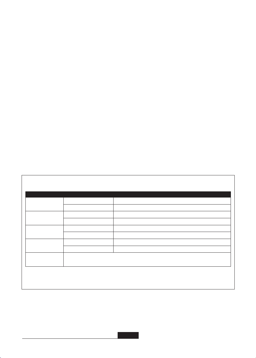
C.
B.
A.
F.
E.
D.
G.
Fig. 3 - Inappropriate Connections
H.
If the connecting element to which a snap hook (shown) or
carabiner attached is undersized or irregular in shape, a
situation could occur where the connecting element applies
a force to the gate of the snap hook or carabiner. This force
may cause the gate (of either a self-locking or a non-
locking snap hook) to open, allowing the snap hook or
carabiner to disengage from the connecting point.
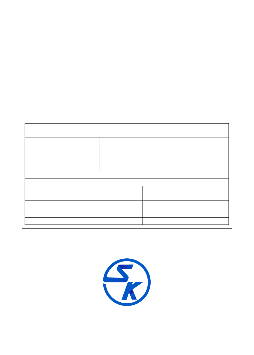
Small ring or other non-compatibly shaped element
1. Force is applied
to the snap hook.
2. The gate presses against
the connecting Ring.
3. The gate opens allowing
the snap hook to slip off.
Fig. 2 - Unintentional Disengagement (roll-out)

6. USE OF FALL ARREST SYSTEM: The fall arrest system MUST ONLY be connected to the back attaching element on the harness
provided for the purpose (”D” ring or webbing attachment extension) or to the chest anchorage points (“webbing link” or “D” link). The
chest anchorage points must imperatively be used together. The D-rings on the belt and the ventral anchorage point must only be used
for the attachment of a work positioning or retaining system and never with a fall arrest system.
During use, check regularly the adjustment and/or attachment points.
7. ANCHORAGE STRENGTH: The anchorage strength required is dependent on the application type. The following are the requirements of
ANSI Z359.1 for these application types:
Ÿ
Ÿ
Fall Arrest: Anchorages selected for fall arrest systems shall have a strength capable of sustaining static loads applied in the
directions permitted by the system of atleast- 1. 5,000 lbs.(23kN) for non-certied anchorages, or 2. Two times the maximum
arresting force for certied anchorages. When more than one fall arrest system is attached to an anchorage, the strengths set
forth in (1) and (2) above shall be multiplied by the number of systems attached to the anchorage.
As Per OSHA: Anchorages used for attachment of personal fall arrest systems shall be independent of any anchorage being used
to support or suspend platforms and capable of supporting at least 5,000 lbs.(23kN) per user attached, or be designed, installed
and used as part of a complete PFAS which maintains a safety factor of at least two, and is under the supervision of a qualied
person.
Work Positioning: The structure to which the work positioning system is attached must sustain static loads applied in the
directions permitted by the work positioning system of at least 3,000 lbs., or twice the potential impact load, whichever is greater.
See OSHA. When more than one work positioning system is attached to an anchorage, the strengths stated above must be
multiplied by the number of work positioning systems attached to the anchorage.
Ÿ Restraint: Anchorages selected for restraint and travel restraint systems shall have a strength capable of sustaining static loads
applied in the directions permitted by the system of at least: 1. 1,000 lbs. (4.5 kN) for non-certied anchorages, or 2. Two times
the foreseeable force for certied anchorages. When more than one restraint and travel restraint system is attached to an
anchorage, the strengths set forth in (1) and (2) above shall be multiplied by the number of systems attached to the anchorage.
Ÿ Rescue: Anchorages selected for restraint and travel restraint systems shall have a strength capable of sustaining static loads
applied in the directions permitted by the system of at least: 1. 3,000 lbs. (13.3 kN) for non-certied anchorages, or 2. Five times
the foreseeable force for certied anchorages. When more than one restraint and travel restraint system is attached to an
anchorage, the strengths set forth in (1) and (2) above shall be multiplied by the number of systems attached to the anchorage.
4
ANCHORAGE & ANCHORAGE STRENGTH: Anchorage and anchorage strength requirements are dependent on the Full Body Harness. In
accordance with ANSI Z3559.1, anchorages selected for fall Arrest Systems must meet the anchorage strength requirements dened in
below:
Anchorage Strength Requirements
1
Fall Arrest
1
Restraint
1
Work Positioning
1
Rescue
Climbing
Non-Certied Anchorage
2
Certied Anchorage:
Non-Certied Anchorage:
2
Certied Anchorage:
Non-Certied Anchorage
2
Certied Anchorages:
Non-Certied Anchorages
2
Certied Anchorage:
5,000 lbs.(23kN)
2 Times the Maximum Arresting Force for Certied Anchorage
1,000 (4.5 kN)
2 times the foreseeable force for certied anchorages.
3,000 lbs (13.3 kN)
2 times the foreseeable force for certied anchorage.
3,000 lbs (13.3 kN)
5 times the foreseeable force for certied anchorage.
1 Multiple Systems: When more than one of the dened system is attached to an anchorage, the strength dened for Non- Certied or certied
anchorage shall be multiplied by the number of systems attached to the anchorage.
2 Certied Anchorage: An anchorage for fall arrest, positioning, restraint, or rescue systems that a qualied person certies to be capable of
supporting the potential fall force that meet the criteria for a certied anchorage prescribed in this standard.
The structure which a climbing system is attached must sustain the loads required by that
particular system. See the instructions for the climbing system for requirements.

8. INSPECTION: Before each use, proceed with thorough visual examination to ensure that the PPE is intact (the same applies for the
equipment used with the harness (connectors, lanyard…) and take all necessary steps concerning the implementation of rescue
in total safety. In the event of your product being contaminated, consult the manufacturer or authorized agent. If you have any
doubts regarding the safe state of the product or if the product has been used to arrest a fall, for your personal safety, it is
essential to withdraw the PPE from service and send it back to the manufacturer or a qualied repair Center for checking or
destruction.
Following the inspection, the center will provide written authorization or refusal for the use of the PPE. Never attempt to modify or
repair PPE.
ŸBefore each use of this equipment inspect it according to the following guidelines: A formal inspection of fall protection
products/components must be performed at least every six months by a competent person other than the user. The
frequency of formal inspections should be based on conditions of use or exposure. Record the inspection results in the
inspection and maintenance log at the end of this manual. The component should be checked for Cut, Frayed, Heavily
Soiled, welding burns etc. Metal parts like D-rings should be duly check for the crack, bent, deformities, corrosions etc.
9. LIMITATIONS:
Ÿ Megapod should be a personal property of its user.
Ÿ It should not be used in highly acidic or basic environments.
10. FITTING & SIZING:
STEP 1: Place the Megapod on the oor with the feet on the ground. Remove
the locking Pins from the head and the legs.
STEP 2: Fully spread the legs and then replace the locking pins on head to
secure the legs in the open positions.
STEP 3: Resecure the locking pins int legs, after adjustment of the required
height or in fully extended position.
STEP 4: Place the Megapod over the entry point. Adjust the Megapod as
necessary by removing pins in one leg at a time. Adjust each leg so the
Megapod sits level above user's entry point. Ensure that all pins are re-
installed.
STEP 5: Place the Retrieval Block on the opposite leg of the Megapod, where
the winch is installed.
11. FALL CLEARANCE: If there is a risk of fall or if the only anchorage is below the attachment points on the harness, it is essential to
use a lanyard provided with an energy absorber. Before using a shock-absorbing lanyard, check that there is sufcient fall
clearance below the user to prevent any collision with the structure or the ground.
The Megapod comes in two variants i.e. 7ft.(2.10) and 10ft
(3.05). Depending on the condition of usage one can choose best option as per
requirement.
12. MATERIAL & CONSTRUCTION:
ŸMaterials: High Strength Aluminium
ŸSystem Requirements:
ŸCompatibility of Components: Safe Keeper Fall Protection
equipment is designed to be used with Safe Keeper approved
components. Please contact Safe Keeper if you have a question
regarding compatibility. Making substitutions without approval
from Safe Keeper Fall Protection may lead to injuries and or death. A
Qualied person can make a determination on compatibility of
equipment from different manufacturers.
ŸCompatibility of Connectors: Connectors (D-rings, hooks,
carabiners) must be capable of supporting at least 5,000 lbs.
(23kN). Do not use equipment that is not compatible. Non-
compatible connectors may unintentionally disengage. Self-
locking snap hooks and carabiners are required by CSA, ANSI
and OSHA. Connectors must be compatible in size, shape, and
strength.
ŸMaking Connections: Only use self-locking snap hooks and
carabiners with any Safe Keeper Fall Protection equipment. Do not
use equipment that is not compatible.
5
SA17-SK (7ft.) SA17-SK (10ft.)

30 10
Ref: SA 17(7ft)
Batch No.: XXXX
Serial No.: XXXX
Date of mfg.: XXXX
14. PRODUCT MARKINGS:
ŸCapacity: 1 user, 310 lbs.(140 kgs)
maximum weight.
ŸStrength: 5000 lbs (23 kN)
13. OTHERS:
ŸMaintenance & Cleaning: Repairs to equipment can be made only by a Safe Keeper representative or person or entity
authorized by Safe Keeper. Contact Safe Keeper for maintenance and repair. Cleaning after use is important for maintaining
the safety and life of the equipment. Cleanse the equipment of all dirt, corrosives, and contaminants. If the equipment cannot
simply be wiped clean use a mild soap and water. Rinse, wipe, and hang to dry in shade.
ŸStorage: Store the anchorage connector component harness in a cool, dry and clean place out of direct sunlight. Avoid areas
where heat, moisture, light, oil, and chemicals or their vapors or other degrading elements may be present. Equipment which
is damaged or in need of maintenance should not be stored in the same area as usable equipment. Heavily soiled, wet, or
otherwise contaminated equipment should be properly maintained (e.g. dried and cleaned) prior to storage.
Prior to using equipment which has been stored for long periods of time, a Formal Inspection should be performed by a
competent person. For harnesses with Dielectric buckles, pass-thru buckles or Quick Connect Buckles, store the harness
with the buckles connected.
ŸTraining: It is the responsibility of the users to assure that they read, understand, and follow all instructions and are trained in
the care and use of this device. Training should be repeated periodically and any time there is a change of components within
the system. Training must be conducted without exposing the trainee to a fall hazard.
MARKING EXPLANATION: The Product is marked with-
(I) The ANSI icon showing that the product meets the
requirements of the PPE Directive.
(ii) Identication of manufacturer's
(iii) Type or product code
(iv) Certifying Norm & Year
(v) Material of Construction
(vi) Load Capacity
(vii) Warning
(viii) Adjustable Height
(ix) Lot No.
(x) Minimum Breaking Strength
(xi) Inspection Chart
(xii) Norm & Year
(xiii) Year of manufacturing
(xiv) Read Instructions before use
(xv) Country of manufacture
6
(ii)
(iii)
(vi)
(v)
(iv)
(ix)
(xiii)
(viii)
(x)
(xi)
( )xiv
(vii)
(i)
( )xv
LABEL

SAFE KEEPER, 314 E. CANAL ST. MULBERRY, FL 33860
15. PERIODIC EXAMINATION: Keep these instructions with the product and ll in the identication sheet, entering the information taken
from the markings.
ŸThe periodic examination is essential to test the resistance and condition of the equipment and to guarantee the safety of the user.
ŸA qualied person must examine this equipment at least once each year in strict compliance with the instructions of the
manufacturer and the previous check must be recorded on the attached sheet.
ŸThe frequency of inspection should be increased in accordance with the regulations, if the equipment is in heavy usage or if the
equipment is used in harsh environments. Check also that the markings are legible.
LIFESPAN: The estimated product Lifespan is 10 years from the date of manufacturing. The following factors can reduce the Lifespan of
the product : intense use, contact with chemical substances, specially aggressive environment, extreme temperature exposure, UV
exposure, abrasion, cuts, violent impacts, bad use or maintenance.
DISCLAIMERS: This information on the product is based upon technical data that Safe Keeper obtained under laboratory conditions
and believes to be reliable. Safe Keeper does not guarantee results and take no liability or obligation in connection with this
information. As conditions of end use are beyond our control it is the user's responsibility to determine the hazard levels and the use
of proper personal protective equipment. Persons having technical expertise should undertake evaluation under their own specic
end-use conditions, at their own discretion and risk. Please ensure that this information is only used to check that the product
selected is suitable for the intended use. Any product that is damaged, torn worn or punctured should be discontinued from usage
immediately.
Periodic examination
next due date
Product
Model & type/Identication
Trade Name
Address
Identication number
Manufacturer
Tel, fax, email into use
Year of manufacture
Purchase Date
Date rst put into use
Other relevant information (e.g. document number)
PERIODIC EXAMINATION AND REPAIR HISTORY
Date
Name and signature
of competent person
Reason for entry
(periodic examination
or repair)
Defects noted, repairs
relevant information
carried out and other
EQUIPMENT RECORD
Table of contents
Other SK Protection Device manuals
Popular Protection Device manuals by other brands

Intermatic
Intermatic IG1201F20 installation instructions

Selcom Security
Selcom Security DT-880 user manual

Siemens
Siemens SINAMICS PERFECT HARMONY GH180 Function manual

Trinity Highway
Trinity Highway QuadGuard II Product description manual

Ultrasonic
Ultrasonic SonicPRO installation manual

Isotronic
Isotronic H1 Instructions for use