!
WARNING!
• All electrical equipment must be connected by a qualified electrician.
See separate connecting directions for electronics.
• The power switch must be permanently mounted and located to allow
easy access when performing maintenance work.
!
WARNING!
Read the separate maintenance instructions before taking the machine
into service.
!
IMPORTANT!
• If a short circuit should occur, make sure that the electrical
equipment is in working order before continuing operation.
• Make usre that the electrical equipment is kept free from dirt, dust,
moisture, and electrostatic charge.
• The machine is not designed to be stood or walked on.
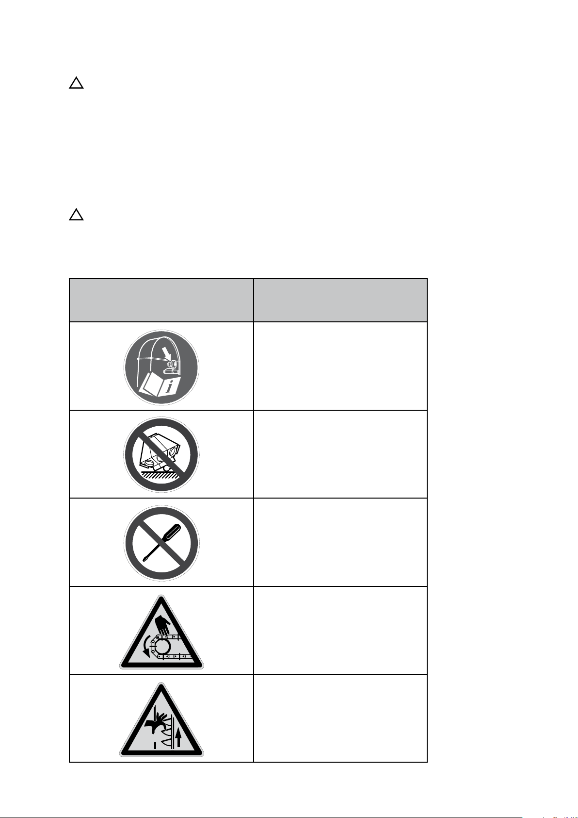
!
WARNING!
• Stop the machinery and turn off electric power before attempting any
type of assembly, electrical connection or maintenance work.
• Do not start the machinery without the lid, hatches, covers, guards,
and connections attached in such a way that they can only be opened
with tools.
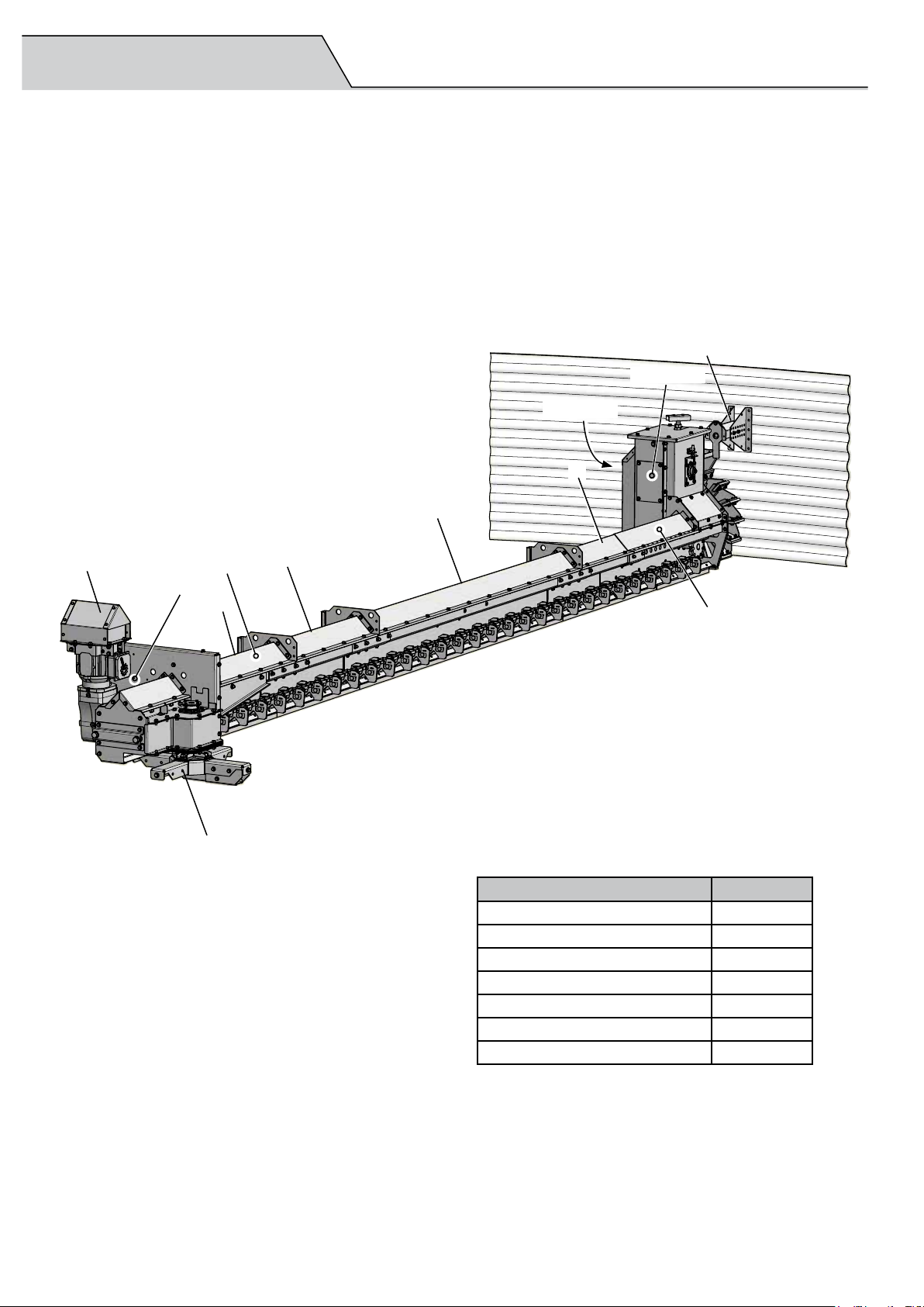
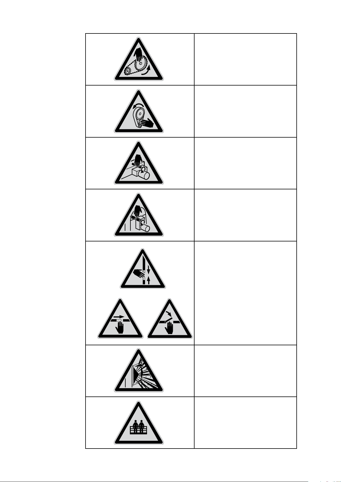
• The sweep conveyor's conveyor chain and forward driving wheel are
not fully built-in for functional reasons. Do not remain in the vicinity of
the machine while it is operating.
• The silo's center and intermediate outlet hoppers are not protected for
functional reasons. Do not remain in the vicinity of the outlet hoppers
while the machine is operating.
• The connections to the bottom conveyor must be firmly attached and
fully sealed.
• The rotating drive shaft is partially exposed between the angle gear
motor and the drive end.
Electrical connection
!
IMPORTANT!
• Make sure the motor protection is set to the correct ampere setting for
the motor.
• Ensure that the rotation guard is engaged during operation.
Maintenance
Inadequate maintenance may lead to personal injury or damage to the
conveyor equipment and/or other equipment. It can also cause malfunctions
or a reduction in capacity.
Incorrect electrical connection may lead to personal injury or damage to the
conveyor equipment and/or other equipment. It can also cause malfunctions
or a reduction in capacity.
8 SKANDIA ELEVATOR – KTIS