Skope OD260 User manual

OD260
Service Manual
MAN800056 Rev. 1.1 April 2020
SKOPE Open Deck Chiller

OD260
SKOPE Open Deck Chiller
Service Manual
MAN80056
Rev. 1.1 April 2020
© 2017 SKOPE Industries Limited. All rights reserved.
SKOPE Industries Limited reserve the right to alter specifications without notice.
is a registered trademark of SKOPE Industries Limited.
SKOPE INDUSTRIES LIMITED
Head Office
PO Box 1091, Christchurch
New Zealand
Freephone: 0800 947 5673
Fax: (03) 983 3896
E-mail: [email protected]
Website: www.skope.com
Trademark Infringement
The SKOPE trademark on this product is infringed if the owner, for the time being, does
any of the following:
• Applies the trade mark to the product after their state, condition, get-up or packaging
has been altered in any manner
• Alters, removes (including part removal) or obliterates (including part obliteration) the
trade mark on the product
• Applies any other trade mark to the product
• Adds to the product any written material that is likely to damage the reputation of the
trade mark
Notice of the above contractual obligations passes to:
• Successors or assignees of the buyer
• Future owners of the product

SKOPE OD260
Service Manual iii
CONTENTS
1Specifications
Models. . . . . . . . . . . . . . . . . . . . . . . . . . . . . . . . . . . . . . . . . . . . . . . . .5
OD260 . . . . . . . . . . . . . . . . . . . . . . . . . . . . . . . . . . . . . . . . . . . . . . 5
2Electronic Controller
Electronic Controller Operations . . . . . . . . . . . . . . . . . . . . . . . . . . . . .6
Introduction . . . . . . . . . . . . . . . . . . . . . . . . . . . . . . . . . . . . . . . . . . 6
Faceplate . . . . . . . . . . . . . . . . . . . . . . . . . . . . . . . . . . . . . . . . . . . . 7
Running the Chiller . . . . . . . . . . . . . . . . . . . . . . . . . . . . . . . . . . . . . . . 8
Operating Modes . . . . . . . . . . . . . . . . . . . . . . . . . . . . . . . . . . . . . . 8
Compressor and Fans . . . . . . . . . . . . . . . . . . . . . . . . . . . . . . . . . . 8
Temperature Probes . . . . . . . . . . . . . . . . . . . . . . . . . . . . . . . . . . .8
Defrost Cycle . . . . . . . . . . . . . . . . . . . . . . . . . . . . . . . . . . . . . . . . .8
Lighting . . . . . . . . . . . . . . . . . . . . . . . . . . . . . . . . . . . . . . . . . . . . . . 8
Messages and Alarms . . . . . . . . . . . . . . . . . . . . . . . . . . . . . . . . . . . . . 9
Controller Display . . . . . . . . . . . . . . . . . . . . . . . . . . . . . . . . . . . . . . 9
Cold Climate Protection . . . . . . . . . . . . . . . . . . . . . . . . . . . . . . . .10
Hardware Setup . . . . . . . . . . . . . . . . . . . . . . . . . . . . . . . . . . . . . . . . 11
Hardware Inputs . . . . . . . . . . . . . . . . . . . . . . . . . . . . . . . . . . . . . . 11
Temperature Settings . . . . . . . . . . . . . . . . . . . . . . . . . . . . . . . . . . 11
Temperature Probe Readings . . . . . . . . . . . . . . . . . . . . . . . . . . . 11
Wiring Termination . . . . . . . . . . . . . . . . . . . . . . . . . . . . . . . . . . . . 11
Programming the Electronic Controller . . . . . . . . . . . . . . . . . . . . . . . 12
Temperature Setpoint . . . . . . . . . . . . . . . . . . . . . . . . . . . . . . . . . 12
Parameters . . . . . . . . . . . . . . . . . . . . . . . . . . . . . . . . . . . . . . . . . . 12
Parameter History . . . . . . . . . . . . . . . . . . . . . . . . . . . . . . . . . . . . .13
3Wiring
Model: OD260 . . . . . . . . . . . . . . . . . . . . . . . . . . . . . . . . . . . . . . . 16
Notes . . . . . . . . . . . . . . . . . . . . . . . . . . . . . . . . . . . . . . . . . . . . . .17
4Spare Parts
Cabinet Assembly - OD260 . . . . . . . . . . . . . . . . . . . . . . . . . . . . . . . . 18
Electrics Plate Assembly . . . . . . . . . . . . . . . . . . . . . . . . . . . . . . . . . .20
Unit Electrics Box Assembly . . . . . . . . . . . . . . . . . . . . . . . . . . . . . . . 21
Refrigeration Unit Assembly . . . . . . . . . . . . . . . . . . . . . . . . . . . . . . . 22
5Installation
Climate Class . . . . . . . . . . . . . . . . . . . . . . . . . . . . . . . . . . . . . . . . . . . . . . 24
Chiller Location . . . . . . . . . . . . . . . . . . . . . . . . . . . . . . . . . . . . . . 24
Air Movement . . . . . . . . . . . . . . . . . . . . . . . . . . . . . . . . . . . . . . . .24
Power Cord . . . . . . . . . . . . . . . . . . . . . . . . . . . . . . . . . . . . . . . . .24
Ventilation . . . . . . . . . . . . . . . . . . . . . . . . . . . . . . . . . . . . . . . . . .24
Stabiliser Feet . . . . . . . . . . . . . . . . . . . . . . . . . . . . . . . . . . . . . . . 26
Shelves . . . . . . . . . . . . . . . . . . . . . . . . . . . . . . . . . . . . . . . . . . . . . . . 27
Installing the Shelves . . . . . . . . . . . . . . . . . . . . . . . . . . . . . . . . . 27
6Replacement Procedures

SKOPE OD260
Service Manual
iv
Isolating Electrics . . . . . . . . . . . . . . . . . . . . . . . . . . . . . . . . . . . . . . . 28
Lighting . . . . . . . . . . . . . . . . . . . . . . . . . . . . . . . . . . . . . . . . . . . . . . . 29
Interior Lights . . . . . . . . . . . . . . . . . . . . . . . . . . . . . . . . . . . . . . . . 29
LED Driver Power Supply . . . . . . . . . . . . . . . . . . . . . . . . . . . . . . 29
Cabinet Electrics . . . . . . . . . . . . . . . . . . . . . . . . . . . . . . . . . . . . . . . 30
Electrics Plate Assembly . . . . . . . . . . . . . . . . . . . . . . . . . . . . . . . 30
Sweat Wire . . . . . . . . . . . . . . . . . . . . . . . . . . . . . . . . . . . . . . . . . . 30
Front Upstand . . . . . . . . . . . . . . . . . . . . . . . . . . . . . . . . . . . . . . . . . . 31
Vertical Bumpers . . . . . . . . . . . . . . . . . . . . . . . . . . . . . . . . . . . . . . . . 31
Wheels . . . . . . . . . . . . . . . . . . . . . . . . . . . . . . . . . . . . . . . . . . . . . . . 31
Honeycomb Air Grille . . . . . . . . . . . . . . . . . . . . . . . . . . . . . . . . . . . . 31
Refrigeration Unit . . . . . . . . . . . . . . . . . . . . . . . . . . . . . . . . . . . . . . . 32
Introduction . . . . . . . . . . . . . . . . . . . . . . . . . . . . . . . . . . . . . . . . . 32
Removing the Refrigeration Unit . . . . . . . . . . . . . . . . . . . . . . . . . 33
Unit Junction Box . . . . . . . . . . . . . . . . . . . . . . . . . . . . . . . . . . . . . 34
Condenser Fan . . . . . . . . . . . . . . . . . . . . . . . . . . . . . . . . . . . . . . 34
Evaporator Fans . . . . . . . . . . . . . . . . . . . . . . . . . . . . . . . . . . . . . 35
Compressor . . . . . . . . . . . . . . . . . . . . . . . . . . . . . . . . . . . . . . . . . 35
Compressor Electrics . . . . . . . . . . . . . . . . . . . . . . . . . . . . . . . . . . 35
Electronic Controller . . . . . . . . . . . . . . . . . . . . . . . . . . . . . . . . . . . . . 36
Introduction . . . . . . . . . . . . . . . . . . . . . . . . . . . . . . . . . . . . . . . . . 36
Removal . . . . . . . . . . . . . . . . . . . . . . . . . . . . . . . . . . . . . . . . . . . . 36
Replacement . . . . . . . . . . . . . . . . . . . . . . . . . . . . . . . . . . . . . . . . 36
Temperature Probes . . . . . . . . . . . . . . . . . . . . . . . . . . . . . . . . . . 37
Condenser Probe . . . . . . . . . . . . . . . . . . . . . . . . . . . . . . . . . . . . . 38
Evaporator Probe . . . . . . . . . . . . . . . . . . . . . . . . . . . . . . . . . . . . . 38
Service Probe . . . . . . . . . . . . . . . . . . . . . . . . . . . . . . . . . . . . . . . 39
Cleaning . . . . . . . . . . . . . . . . . . . . . . . . . . . . . . . . . . . . . . . . . . . . . . 40
Cabinet . . . . . . . . . . . . . . . . . . . . . . . . . . . . . . . . . . . . . . . . . . . . . 40
Condenser Coil . . . . . . . . . . . . . . . . . . . . . . . . . . . . . . . . . . . . . . 40
7Troubleshooting

5
SKOPE OD260
Specifications
Service Manual
1Specifications
Models
This service manual is applicable to the SKOPE chillers detailed below. The
type is used to distinguish between different models throughout this manual.
OD260 Cabinet
Refrigeration Unit
Model Description Type
OD260 2 × interior lights O26CY
Description Open Deck Chiller
Type O26CY
Construction
Insulation 40mm thick, polyurethane foam. Cyclo-iso Pentane
blowing agent: C5H10/C5H12
Doors n.a.
Dimensions External Internal
Height 1400mm 850-910mm
Width 650mm 565mm
Depth 735mm (includes rear
spacer) 495-595mm
Floor area 0.48m2(includes rear spacer)
Internal volume 230 litres
Shelves
2 × flat or angled (8°), adjustable height shelves, and 1 ×
fixed, angled bottom shelf.
Top shelf: 545mm wide ×
296mm deep. Middle shelf: 545mm wide × 371mm deep.
Bottom shelf: 545mm wide × 442mm deep.
Operating conditions
Climate class: 3. Tested at 25°C
Product temp. range 1°C to 5°C (2°C to 4°C product mass average)
Electrical 220-240 Volts a.c. 50 Hz, single phase supply
Tot al run A m p s 3.2 Amps (includes unit 3.0 Amps)
Sign lighting n.a.
Internal lighting 2 × 9 Watt LED strip side lights (18 Watts total)
Description Electronically controlled, bottom mounted SKOPE
refrigeration unit
Unit model UB89ABF-107IE
Compressor Embraco NEK6210Z
Controller Carel S4 Evo
Nominal capacity 815 Watts
Refrigerant R134a / 420 gms

6Electronic Controller
Service Manual
SKOPE OD260
2Electronic Controller
Electronic Controller Operations
Introduction The chiller is fitted with a Carel S4 Evo electronic controller which is visible
through a cutout in the cabinet front panel, and is housed inside the
electronic controller box assembly at the front of the refrigeration unit.
The electronic controller controls and displays the chiller temperature, and
signals temperature alarms.
To ensure efficient operation, the electronic controller automatically forces a
defrost cycle when required.
The electronic controller is pre-programmed. SKOPE does not recommend
that settings be changed unless it is absolutely necessary.

7
SKOPE OD260
Electronic Controller
Service Manual
Faceplate Because the electronic controller plays such an important role, it’s helpful to
know the parts of the faceplate you may use.
ES
12
3
4
5
68
7
No. Item Description
1
Digital display of cabinet temperature or messages.
The temperature is what the sensor inside the chiller detects,
and not necessarily the product temperature. However, they
may be very close depending on how the controller is set to
sense temperature.
2Up: Button. Used for programming.
3Set (mute): Button. Press to mute the alarm. Press and hold
to access parameters. Also used for programming.
4Light (down): Button. Press to switch the cabinet light on
and off. Also used for programming.
5
Defrost: Indicator. ON when the defrost is activated. Flashes
when the activation of the defrost is temporarily delayed due
to procedures in progress.
6
Compressor: Indicator. ON when the compressor and
condenser fan starts. Flashes when activation of the
compressor is temporarily delayed.
7
Fan: Indicator. ON when the internal cabinet fans are
activated. Flashes when activation of the fans is temporarily
delayed.
8Alarm: Indicator. ON when alarm is signalled.
ES

8Electronic Controller
Service Manual
SKOPE OD260
Running the Chiller
Operating
Modes The electronic controller runs the chiller in constant ‘Normal’ mode. The
OD260 does not use an energy saving/night mode (or similar).
Note: Normal mode is suitable for perishable product (all shelves maintain
temperature below 5°C).
During some conditions or refrigeration system alarms, the electronic
controller may run the chiller in cold climate protection mode, or may shut
down the lights and/or refrigeration system. Refer to “Cold Climate
Protection” on page 10, or “Messages and Alarms” on page 9 for more
information.
Compressor
and Fans The compressor and condenser fan will start just after the chiller is turned
on. The compressor and condenser fan will stop when the control probe
temperature reading reaches 2.0°C (parameter St), and on again when it
reaches 4°C (parameter St + rd).
The evaporator fan starts approximately 3 seconds (parameter F0) after the
compressor and condenser fan. To verify, check that the FAN light is lit on
the electronic controller faceplate.
Temperature
Probes Three temperature probes feed data to the electronic controller: the control
probe, the evaporator probe, and the condenser probe.
The control probe monitors and controls the chiller temperature, provides
the chiller temperature for the electronic controller to display, and notifies the
electronic controller of any erratic or abnormal temperatures that could
identify an issue within the refrigeration system.
The evaporator probe controls the refrigeration system defrost initiation and
termination.
The condenser probe monitors the refrigeration system condenser
temperature and notifies the electronic controller of any abnormally high
temperatures that could identify an issue within the refrigeration system.
Refer to page 37 for service information.
Defrost Cycle The defrost cycle will begin after 2 hours (parameter dl) of compressor run
time. During the defrost cycle the compressor stops and the evaporator fan
runs continuously. The defrost cycle will terminate when the evaporator
probe reaches 4°C (parameter dt), or after the defrost cycle has been
running for 30 minutes (parameter dP).
Lighting Press the Light button on the electronic controller faceplate to manually
switch the lights on and off.
9
SKOPE OD260
Electronic Controller
Service Manual
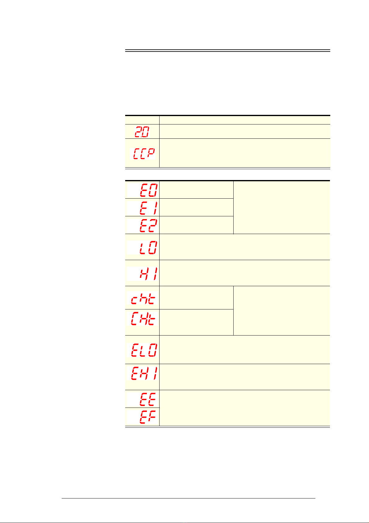
Messages and Alarms
Controller
Display The following table explains messages and alarms that the electronic
controller displays.
Alarms signal unexpected operational changes in the chiller and can be
muted by pressing the set (mute) button on the electronic controller
faceplate (see page 7).
Messages
Alarms
Display Description
The chiller is in Normal mode and the electronic controller displays the
chiller temperature.
The chiller is in Cold Climate Protection mode. The chiller enters Cold
Climate Protection mode if the control probe detects the interior
temperature below -0.3°C (parameter St - CCt) for more than 30 minutes
(parameter CCd). The lights remain on and cannot be switched off (see
over page for more information).
Probe 1 error.
See parameters (page 12) for probe
function.
Probe 2 error.
Probe 3 error.
Low temperature alarm. An alarm sounds. The temperature inside
the chiller is too cold and an alarm sounds. The controller will
automatically reset the alarm once the temperature inside the chiller
raises.
High temperature alarm. An alarm sounds. The temperature inside
the chiller is too warm and an alarm sounds. The controller will
automatically reset the alarm once the temperature inside the chiller
drops.
Refrigeration system high
temperature
Pre-warning (auto reset)
1. Check refrigeration ventilation and
ensure the cabinet is installed in a
suitable location (see page 24).
2. To reset the ‘CHt’ alarm - unplug
the cabinet from the power supply
for 1 minute, then reconnect to
power supply.
Refrigeration system high
temperature
Shutdown (manual reset)
Low voltage alarm. An alarm sounds. The mains voltage is low. An
alarm sounds and the controller switches off the compressor. The
controller will automatically reset the alarm once the mains voltage
raises.
High voltage alarm. An alarm sounds. The mains voltage is high. An
alarm sounds and the controller switches off the compressor. The
controller will automatically reset the alarm once the mains voltage
drops.
Electronic controller fault.

10 Electronic Controller
Service Manual
SKOPE OD260
Cold Climate
Protection The chiller will enter cold climate protection (CCP) mode if the ambient
temperature becomes too cold. This happens if the control probe (at the
evaporator air out) detects the interior temperature below -0.3°C (parameter
St - CCt) for more than 30 minutes (parameter CCd). The lights will stay on
and cannot be switched off while the chiller is in CCP mode. The chiller will
return to Normal operation mode once the control probe reading raises to
2°C (parameter St).

11
SKOPE OD260
Electronic Controller
Service Manual
Hardware Setup
Hardware
Inputs The controller has three hardware inputs as detailed in the table below. All
use pin 9 as common.
Electronic controller hardware inputs
Temperature
Settings Standard temperature settings are set-up for perishable product. All product
temperatures are continuously below 5°C. The temperature can be altered
by changing the set point (parameter St).
Temperature
Probe
Readings
Control probe
If parameter /4 is set to 1, the control probe temperature reading is displayed
on the controller faceplate during normal operation. If parameter /4 is not set
to 1, it can be changed to 1 to view the control probe temperature reading.
Condenser probe
To view the condenser probe temperature reading, press the ES (up) and
Set (mute) buttons simultaneously. The temperature reading will display on
the controller faceplate.
Evaporator probe
To view the evaporator probe temperature reading, enter the parameter
menu and navigate to parameter d/2 to display the evaporator probe
reading.
Wiring
Termination Refer to the diagram below for controller termination details.
Pins (on rear of
controller)
Hardware description
9-8 Control probe
9-10 Condenser probe
9-11 Evaporator probe
Condenser Probe (10)
Evaporator probe (11)
Common (9)
Control probe (8)
Supply (6, 7)
Compressor (4, 5)
Lights (1)
12 Electronic Controller
Service Manual
SKOPE OD260
Programming the Electronic Controller
The electronic controller parameter configuration program is set by SKOPE
at the factory. A label on the controller box indicates the parameter
configuration program number (e.g. the OD260 uses program 107).
The electronic controller parameters can be modified using the keypad.
Frequent parameters can be accessed and changed without entering a
password (e.g. temperature setpoint). Locked parameters are protected by
a password to prevent accidental or unauthorised modifications.
Temperature
Setpoint
The chiller temperature setpoint is factory set at 2°C for storage of
perishable products (all shelves maintain temperatures below 5°C). The
cabinet setpoint can be adjusted between 0°C and 4°C if required (see over
page).
SKOPE do not recommend that the setpoint be changed unless it is
absolutely necessary, and then only by small increments at a time.
To view and adjust the temperature setpoint
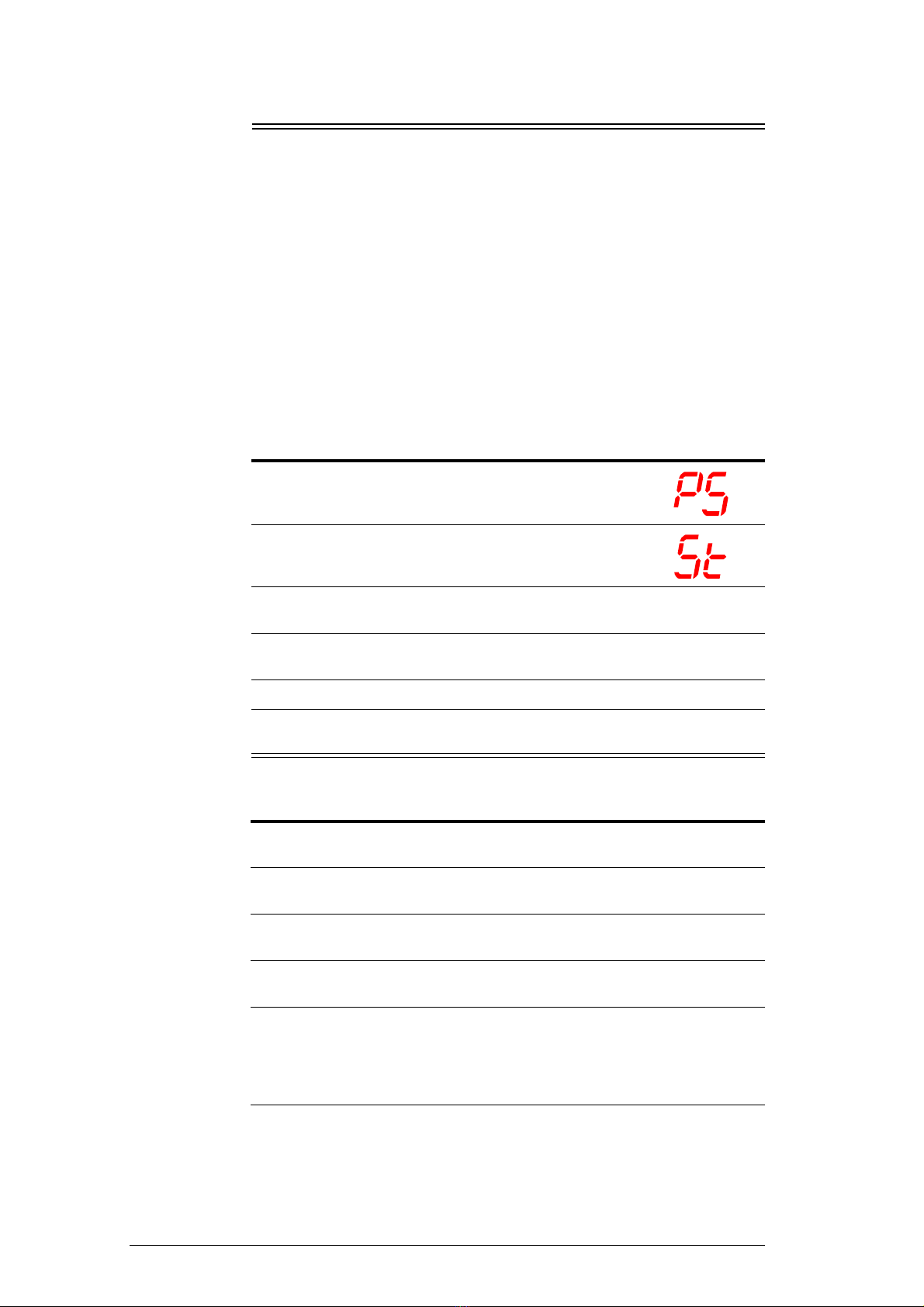
Parameters Follow the steps below to access the locked parameters.
To access the locked parameters
1. Press and hold the Set (mute) button for 3 seconds
until PS is shown on the display, indicating entry into
the controller settings menu.
2. Press the up or down button to scroll the menu until St
is shown on the display.
3. Press the Set (mute) button. The current setpoint value is shown on the
display.
4. Press the up or down button to increase or decease the setpoint value to the
required temperature.
5. Press the Set (mute) button to temporarily save the setpoint value.
6. Press and hold the Set (mute) button for 3 seconds to permanently save the
setpoint value and exit the controller settings menu.
1. Press and hold the Set (mute) button for 3 seconds until the display shows
‘PS’.
2. Press the Set (mute) button to access the password parameter, ‘0’ is
displayed.
3. Use the ES (up) and Light (down) buttons to display the password ‘22’
(default password).
4. Press the Set (mute) button to confirm the password. The display shows
‘PS’.
5. Use the ES (up) and Light (down) buttons to scroll the parameter codes and
locate the required parameter.
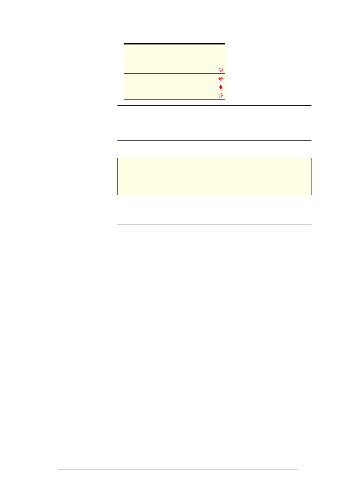
Parameter categories can be identified by the initial symbol or letter of the
code, and the icon displayed on the electronic controller faceplate:
Continued over page
13
SKOPE OD260
Electronic Controller
Service Manual
Parameter
History To see if the parameters have changed from the factory settings, check the
H5 parameter. If it is a positive value the parameters are still at factory
settings. If H5 is a negative value, the parameters have been changed and
are not at factory settings.
6. Press the Set (mute) button to display the value associated with the
parameter code.
7. Use the ES (up) and Light (down) buttons to increase or decrease the value
of the parameter.
8. Press the Set (mute) button to temporarily save the new value. The display
shows the parameter code.
IMPORTANT
If no buttons are pressed for 60 seconds or the power is
disconnected before the temporarily saved values are
permanently saved, the temporarily saved values will be
cancelled and the previous setting will be restored.
9. If necessary, repeat steps 5 - 7 to change other parameters as required.
10. Press and hold the Set (mute) button for 3 seconds to permanently save the
parameters and exit the parameter menu.
Category Initial Icon
Probe parameters / -
Control parameters r -
Compressor parameters c
Defrost parameters d
Alarm parameters A
Fan parameters F

14 Electronic Controller
Service Manual
SKOPE OD260
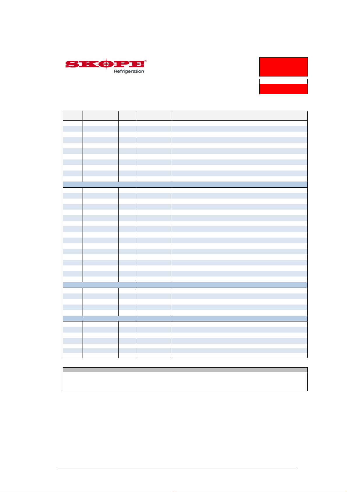
Parameter list - Program 107 - OD260 (page 1 of 2)
Revision: 1.1
Application
OD260
Controller Type
SKOPE S4 EVO
Controller Model & Revision
PZSKC0H002K (Rev 1.414)
SKOPE Part Number
ELZ11478-107
Setting Unit
SET0 Min Max
Probe Parameters
PS 22 F0200
Password (Read Only)
/2 15 C115
Measurement stability (Applies to all probes)
/4 1 C15
Select probe displayed
/5 0 C01
Select °C/°F ( 0=°C ; 1=°F )
/6 0 C01
Disable decimal point
/8 0.0 °C C -99.00 99.0 Display Offset (Only if /E > 0)
/9 0.0 °C C -40.0 /A Minimum Display value (Only if /E > 0)
/A 199 °C C /9 /b Maximum Display Value (Only if /E > 0)
/b 199 °C C /A 199 Visualization Error Threshold (Only if /E > 0)
/E 1 C050
Display Dampening Coefficient
/C1 1.5 °C C -50.0 50.0 Probe 1 Calibration Offset
/C2 0.0 °C C -50.0 50.0 Probe 2 Calibration Offset
/C3 0.0 °C C -50.0 50.0 Probe 3 Calibration Offset
Regulation Parameters
St 2.0 °C F r1 r2 Set point
rd 2.0 °C C 0.0 19.0 DAY differential
r1 0.0 °C C -50.0 r2 Minimum set point value
r2 4.0 °C C r1 150 Maximum set point value
r3 0 C01
Enable Auto Day/Night Mode Switching
r4 0.0 °C C -50.0 50.0 Night Mode set point delta (added to St)
r5 2.0 °C C 0.0 19.0 Night differential
r6 0 hrs C 0 90 Night Mode Start Delay (time period with no door openings)
r7 90 hrs C 1 90 Night Mode Timeout (time period in night mode)
r10 0 hrs C 0 24 Light Delay On Time after entering DAY mode
Cold Climate Protection Parameters
CCt 2.0 °C C 0.1 20.0 Cold Climate Protection Temperature Delta
CCd 30 mins C 0 199 Cold Climate Protection Delay
Pull Down Mode Parameters
Pt 127 °C C 0 127 Pull-down Mode - Activation Temperature
Pd 250 hrs C 0 250 Pull-down Mode - Maximum Duration
Compressor Parameters
c0 1 mins C 0 200 Comp. and Fan start delay at power-up.
c1 0 mins C 0 100 Minimum time between consecutive compressor starts
c2 3 mins C 0 100 Minimum compressor off time
c3 3 mins C 0 100 Minimum compressor on time
c4 10 mins C 0 100 Compressor on time with duty setting
c5 1 C01
Enable mains voltage protection (0 = disabled, 1 = enabled)
Defrost Parameters
d0 0 C01
Type of defrost ( 0 = Electric, 1 = Hot Gas)
dI 2 hrs C 0 199 Defrost interval time (Time between defrosts)
d2 1 C01
Run defrost interval timer only when compressor running
dt 4 °C C -50.0 127 Defrost Termination temperature
dP 30 mins C 1 199 Maximum defrost duration
d4 0 C01
Defrost request at power-on: (0 = no, 1 = yes)
d5 0 mins C 0 199 Defrost delay on power-up (when d4=1)
d6 1 C01
Display during defrost (0 = "dEF", 1 = Temperature at start of defrost)
dd 0 mins C 0 15 Dripping time (compressor and fans stopped after defrost)
d8 0 mins C 0 199 Bypass high temperature alarm after defrost or door opening
Parameter
107
CPS1017-107-SET0
Last revised on
12-Feb-2018
Full List
SET0
Access
Level
Range
Description
Electronic Controller Parameter Sheet
Page 1 of 2
15
SKOPE OD260
Electronic Controller
Service Manual
Parameter list - Program 107 - OD260 (page 2 of 2)
Revision: 1.1
Application
OD260
Controller Type
SKOPE S4 EVO
Controller Model & Revision
PZSKC0H002K (Rev 1.414)
SKOPE Part Number
ELZ11478-107
Setting Unit
SET0 Min Max
Parameter
107
CPS1017-107-SET0
Last revised on
12-Feb-2018
Full List
SET0
Access
Level
Range
Description
Electronic Controller Parameter Sheet
d9 0 C01
Defrost priority over compressor protectors
d/1 - °C F - - Probe reading on 2nd Input (read only)
d/2 - °C F - - Probe reading on 3rd Input (read only)
d10 -9.0 °C C -50.0 127 On demand defrost Start Temperature
d11 10 mins C 0 60 On demand defrost: start delay
d12 127 °C C -50.0 127 Enabling defrost condition: Control probe threshold
d13 1 C01
Evaporator Fans During Defrost (0 = Off 1 = ON)
d19 15 mins C 0 200 No Downward Tendency Defrost - Start Delay (0 = function disabled)
d20 15 mins C 1 < d19 No Downward Tendency Evaluation (Sample Time)
d21 0 C05
Number of NDT defrosts before R.S.F. "Err" alarm (0 = function disabled)
d22 0.1 °C C 0.0 5.0 No Downward Tendency Evaluation (Temperature Delta)
Alarm & Input Configuration Parameters
A0 -2.0 °C C -20.0 20.0 Temperature Alarm Differential
AL 0.0 °C C -50.0 150 Low temperature alarm setpoint. (Relative if A0>0, Absolute (A0≤0)
AH 10.0 °C C -50.0 150 High temperature alarm setpoint. (Relative if A0>0, Absolute (A0≤0)
Ad 120 mins C 0 199 Temperature alarm delay ( 0 = AL and AH alarms disabled)
A10 0 mins C 0 10 Door Open Alarm delay (0 = door open alarm disabled)
A11 2 C05
2nd Input Configuration
A12 3 C016
Number of cA alarm events to trigger manual reset 'CA' alarm
A13 24 hrs C 0 240 cA alarm counter reset delay
A14 60 mins C 0 240 cA alarm reset delay
A15 1 C01
Lights switched OFF when CHt, cA or CA alarm occurs
A18 1 C01
Allow power cycle to reset CA alarm
A20 15 mins C A10 60 Faulty door/curtain switch E2 alarm delay
Ac 60.0 °C C -50.0 250 High condenser temperature alarm set point
AE 10.0 °C C 0.1 20.0 High condenser temperature alarm differential
Acd 0 mins C 0 250 High condenser temperature alarm delay
Acr 1 C02
High condenser temperature alarm reset method
A21 1 C05
3rd Input Configuration
Evaporator Fan Parameters
F0 3 secs C 1 100 Loads Activation Delay
Fd0 20 mins C 1 100 Fan DAY Duty Cycle : ON time
FdF 0 mins C 0 100 Fan DAY Duty Cycle : OFF time
Fn0 25 mins C 1 100 Fan NIGHT Duty Cycle : ON time
FnF 0 mins C 0 100 Fan NIGHT Duty Cycle : OFF time
Other Parameters
H0 1 C 0 207 Supervisor Serial address
H01 1 C01
Baud Rate (0 = 9600, 1 = 19200)
H02 2 C02
Stop Bits
H03 0 C02
Parity ( 0 = None, 1 = Odd, 2 = Even)
H2 2 C03
Enable Keypad
H4 0 C01
Disable buzzer (0 = Buzzer Enabled, 1 = Buzzer Disabled)
H5 107 F 0 199 ID code (read-only)
Warning
1. Only make program modifications with reference to relevant Operating Manual.
2. This programming sheet is exclusively for SKOPE refrigeration systems with its dedicated Carel controller.
3. Any alteration from this program may adversely affect the SKOPE Refrigeration System operation.
4. Specification may change without notice. Please check with SKOPE Customer Service for latest revision.
Page 2 of 2

16 Wiring
Service Manual
SKOPE OD260
3Wiring
Model: OD260
WIRE COLOURS
BK Black
BN Brown
RD Red
OG Orange
GN Green
BU Blue
GY Grey
WH White
GNYE Green-Yellow
Based upon IEC 757 Standard
LEGEND
T1 Unit terminal S3 & P3 Compressor socket and plug (blue 4-way)
T2 Evaporator fan junction box terminal S4 & P4 Condenser fan socket and plug (red 4-way)
T3 Cabinet terminal S5 & P5 Evaporator fan socket and plug (white 4-way)
T4 Cabinet light and terminal S6 & P6 LED power supply output socket and plug (white 4-way)
T5 Heater wire terminal S7 & P7 Control probe socket and plug (blue 2-way)
S1 & P1 IEC mains isolation socket and plug S8 & P8 Condenser probe socket and plug (red 2-way)
S2 & P2 Unit to cabinet socket and plug S9 & P9
Evaporator probe socket and plug (black 2-way)
LED Ballast
N
L
+
-
T
1-1 & 2
S2-2 P2-2
S2-4 P2-4
EMC Filter
M
M
T1-3 &
4
BU
BN
Evaporator
Fan
Condenser
Fan
T5-2
BU
RD
BK
BU
P2-1 S2-1
BN BN
BN
M
Evaporator
Fan
T2-2
T2-1
BUBN
BN
GNYE
BU
GNYE
T3-2
RD RD
BK
BK
T4-1
T4-2
Cabinet Heater Wire
BU
T3-1
WH
Left
Cabinet Light
BN BU
S1-L P1-L P1-N S1-N
BN BU
BU
BU
BN
BN
BU
BN
Fuse
3A
LNE
BU
BU
T5-1T3-3
BN
BN
BN
Right
Cabinet Light
BN BU
P5-1 S5-1
S3-2 P3-2
S4-2 P4-2 S4-1 P4-1
S3-1 P3-1
S5-2 P5-2
S6-4 P6-4
S6-3 P6-3
RD
S6-2 P6-2
RD
BK
S6-1 P6-1
BK
BU
6 7
4 5
2
Fan
3
1
Lights
8
9
10
11
S4 EVO
Comp.
BN
OG
BK
Embraco Compressor
C
S
St ar t C apac it o r
Relay
Ove rlo ad Compressor
L
N21
R
BU
BU
BN
WH
S7-1 P7-1
BK
BK
OG
BK
RD
BK
BK
BK
BK
S7-2 P-2
S8-1 P8-1
S8-2 P8-2
S9-1 P9-1
S9-2 P9-2
Cabinet
Probe
Evaporator
Probe
Condenser
Probe
BK
BK
T6-1
BK
BN
BK
P4-4

17
SKOPE OD260
Wiring
Service Manual
Notes
18 Spare Parts
Service Manual
SKOPE OD260
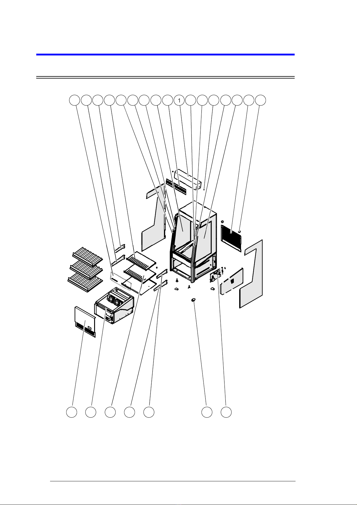
4Spare Parts
Cabinet Assembly ‐OD260
15 14
17
91110
18
12 81110 126 4 3
5
113
6
2
19
7
416
1
10
10
11
11
2
3
4
4
5
6
6
7
8
9
19
SKOPE OD260
Spare Parts
Service Manual
Parts — Cabinet OD260
*See page 27 for information on shelf bracket variations
Item Description SKOPE Part No.
Standard White Black
1Plastic lid -PLM1662A-WH PLM1662A-BK
2Plastic lid screw -PLM10437WH PLM10437BK
3Top shelf -O260/591C-32 O260/591C-49
4
Top shelf bracket - one part version* -STY11671-32 STY11671-49
Top shelf bracket LH - two part
version* -STY10956L-32 STY10956L-49
Top shelf bracket RH - two part
version* -STY10956R-32 STY10956R-49
Top shelf height adjustment piece LH
- two part version* -O230C/598CL-32 O230C/598CL-49
Top shelf height adjustment piece RH
- two part version* -O230C/598CR-32 O230C/598CR-49
5Middle shelf* -O260/591B-32 O260/591B-49
6
Middle shelf bracket* -STY11670-32 STY11670-49
Middle shelf bracket LH - two part
version* -STY10955L-32 STY10955L-49
Middle shelf bracket RH - two part
version* -STY10955R-32 STY10955R-49
Middle shelf height adjustment piece
LH - two part version* -O230C/598BL-32 O230C/598BL-49
Middle shelf height adjustment piece
RH - two part version* -O230C/598BR-32 O230C/598BR-49
7Point of sale header --PLE11610-0550
8Side window RH GLA11663R - -
9Side window LH GLA11663L - -
10 Vertical bumper strip --PLE4077BK-260L
11 Light module ELL11123 - -
12 Light cover O260/E71 - -
13 Acrylic upstand PLY11672 - -
14 Rear spacer RUM4105 - -
15 Rear panel -O260/N86-32 O260/N86-49
16 Front panel -O260/131-32 O260/131-49
17 Castor SXX10289 - -
18 Electrics plate assembly O260/G29 - -
19 Refrigeration unit assembly UB89ABF-107IE - -

20 Spare Parts
Service Manual
SKOPE OD260
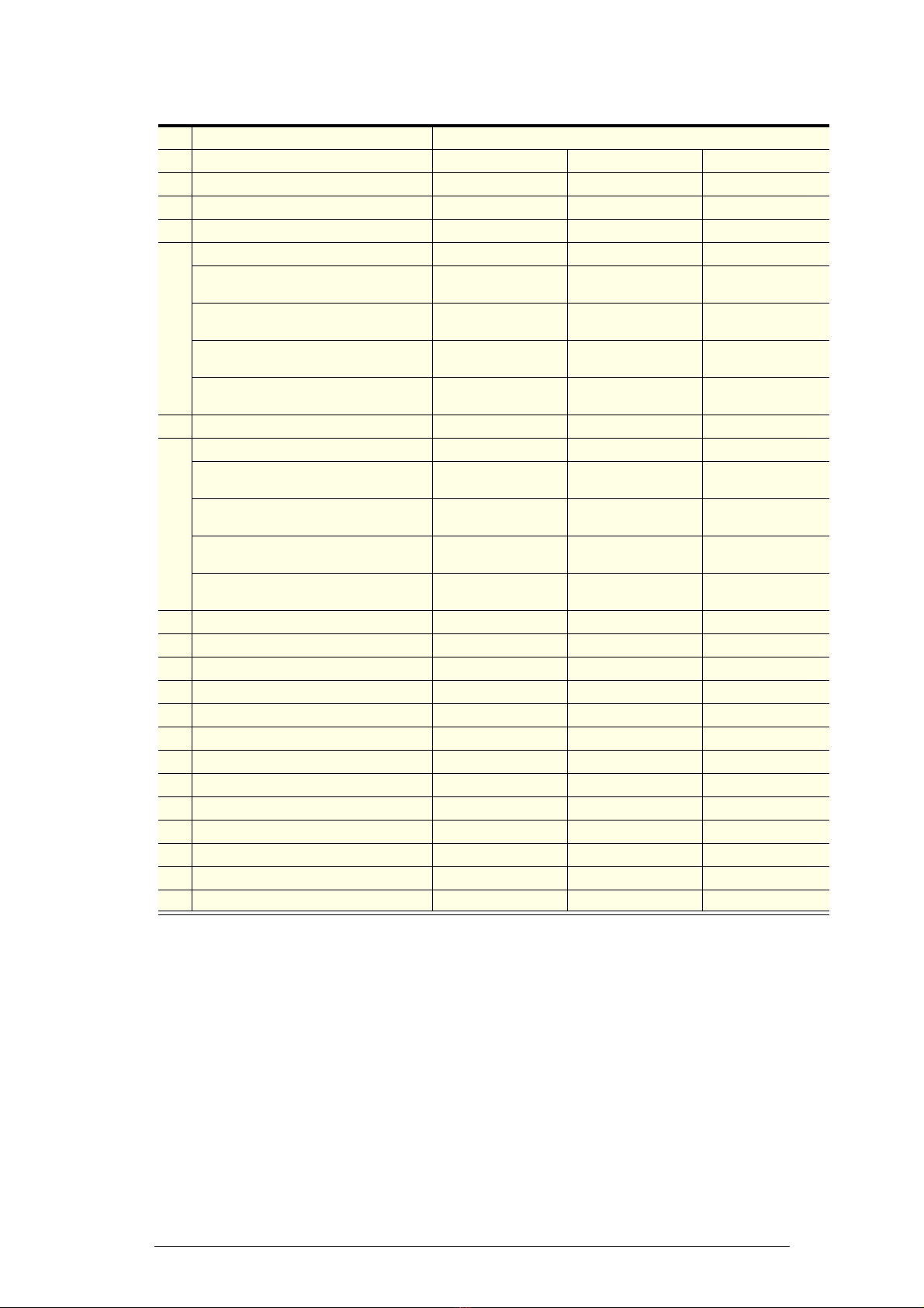
Electrics Plate Assembly
Parts — Electrics Plate Assembly
Item Description SKOPE Part No.
0Electrics plate assembly O260/G29
1EMI filter ELZ10136
2Light power supply O260/K08
33A fuse ELZ9654
Fuse holder ELZ9655
132
1
2
3
Table of contents
Other Skope Chiller manuals

Skope
Skope ActiveCore TME-N Series User manual

Skope
Skope TME1000 User manual

Skope
Skope BME1200-AC User manual

Skope
Skope SERENE SC112G User manual

Skope
Skope TME ActiveCore Series User manual

Skope
Skope BB Series User manual

Skope
Skope OD400-2 User manual

Skope
Skope TME Series User manual

Skope
Skope TME1000 User manual

Skope
Skope B600G-2 User manual

Skope
Skope ActiveCore BME-N Series User manual

Skope
Skope Pegasus PG100HC-2 User manual

Skope
Skope SC112N-AC User manual

Skope
Skope B1200-2 User manual

Skope
Skope SK650-2 Service manual

Skope
Skope TME-N ActiveCore User manual

Skope
Skope BB Series User manual

Skope
Skope TME650N-3C User manual

Skope
Skope SC112N-AC User manual

Skope
Skope OD460 User manual


