Sloan CX 8154-1.6 User manual

INSTALLATION INSTRUCTIONS FOR
SLOAN CX SENSOR CLOSET AND URINAL FLUSHOMETERS
Code No: 0816858
Rev. 3 (07/20)
LIMITED WARRANTY
Sloan Valve Company warrants its ushometer to be made of rst class materials, free from defects of material or workmanship under
normal use and to perform the service for which they are intended in a thoroughly reliable and efcient manner when properly installed and serviced, for a period of
three (3) years (one year for special nishes) from the date of purchase. During this period, Sloan Valve Company will, at its option, repair or replace any part or parts
that prove to be thus defective if returned to Sloan Valve Company, at customer’s cost, and this shall be the sole remedy available under this warranty. No claims will
be allowed for labor, transportation or other incidental costs. This warranty extends only to persons or organizations that purchase Sloan Valve Company’s products
directly from Sloan Valve Company for purpose of resale. This warranty does not cover the life of batteries.
THERE ARE NO WARRANTIES THAT EXTEND BEYOND THE DESCRIPTION ON THE FACE HEREOF. IN NO EVENT IS SLOAN VALVE COMPANY RESPONSIBLE FOR ANY CONSE-
QUENTIAL DAMAGES OF ANY MEASURE WHATSOEVER.
1
Sensor Closet Flushometers
CX 8158-1.6
CX 8158-1.28
CX 8154-1.6
CX 8154-1.28
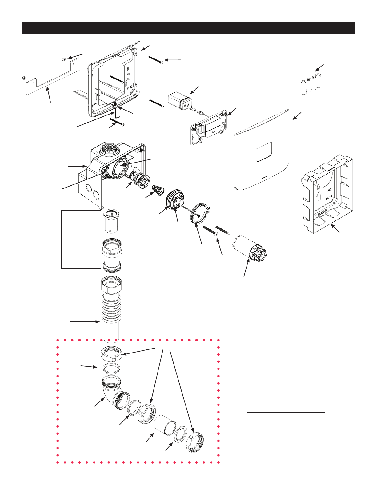
ITEMS INCLUDED (VALVE BOX)
1. Valve Box
2. Mud Guard
3. Adjustment tool
4 Mud Guard Screws
5 Activation Assembly Screws
6. Instructions
7. Adjustable Tube
8. Outlet Connection
9. Elbow
10. Inlet Adapter
11. Vacuum Breaker Assembly
12. Couplings & Gaskets
PRIOR TO INSTALLATION
Sensor Urinal Flushometer
CX 8198-0.5
CX 8198-0.25
CX 8198-0.125
This valve is designed for new construction or where there is easily accessed plumb-
ing for the xture and valve. This valve is designed for a minimum 6-1/2 inch (165
mm) wall space depth. Distance from the center of the valve (inlet or outlet pipe) to
the nished surface of the wall can vary from 3-1/4” – 4-1/4” (83 – 108 mm).
Wall plate opening must be a minimum of 7-3/8” wide x 8-3/8” tall (187 mm wide
x 213 mm tall) to maximum 7-5/8” wide x 8-5/8” tall (194 mm wide x 219 mm
tall). Mud plate is provided and must accompany valve for proper installation. Mud
plate is removed after wall is nished.
TOOLS AND ITEMS REQUIRED FOR INSTALLATION (PROVIDED)
• 5/64” hex wrench • Wall plate depth guide • Adjustment tool
TOOLS AND ITEMS REQUIRED FOR INSTALLATION (NOT PROVIDED)
• Smooth-jawed wrench (at least 2”) • Philips screwdriver • threaded sweat solder adapter
• approximately 15”-18” pipe
1.Valve Box
3.Adjustment Tool
4.#8-32 Mud
Guard Screws
5. 1/4-20 Activation
Assembly Screws
6. Instructions
7. Adjustable Tube 8. Outlet Connection
9. Elbow 10. Inlet Adapter
11. Vacuum Breaker
Assembly
2. Mud Guard
12. Couplings & Gaskets
V651A
Kit

2
ITEMS INCLUDED (WALL PLATE BOX)
IMPORTANT:
• INSTALL ALL PLUMBING IN ACCORDANCE WITH APPLICABLE CODES AND REGULATIONS.
• WATER SUPPLY LINES MUST BE SIZED TO PROVIDE AN ADEQUATE VOLUME OF WATER FOR EACH FIXTURE.
• FLUSH ALL WATER LINES PRIOR TO MAKING CONNECTIONS.
Sloan’s ushometers are designed to operate with 20 to 80 psi (138 to 552 kPa) of water pressure. THE MINIMUM PRESSURE REQUIRED
TO THE VALVE IS DETERMINED BY THE TYPE OF FIXTURE SELECTED.
Consult xture manufacturer for minimum pressure requirements. Most high efciency water closets require a minimum owing pressure of 25 psi
(172 kPa). Many building codes and the ASME A112.19.2 xture standard list maximum static water pressure as 80 PSI (552 kPa).
MODEL 8158
CLOSET
WALL HUNG
REAR INLET
ROUGH-IN CLOSETS
1½” (38 mm)
1½” min. ADA
(38 mm)
33”
(836 mm)
top of plate
1½” (38 mm)
ADA 36” MAX.
(914 mm)
7-1/2” (191 mm)
NO
TE: If fixture inlet i
s
b
e
l
ow r
i
m
l
eve
l,
consu
l
t
fl
oo
r m
ou
nt r
ea
r inl
e
t
rou
g
h-in dimensions.
V
alve
C
L to
f
ixture inlet
:
12
¼”
- 12
½
”
(
311 mm-318 mm
)
11“-11
¼
” (279-286 mm)
I
nlet
p
i
p
e CL to fin. wall
3
¼” - 4
¼
”
(83 mm - 108 mm)
Rear o
f
valve to
f
in. wall
5
¼
”
- 6
¼
”
(
134 mm - 160 mm
)
Fixture inlet to wall opening:
n
let
t
5
¾” -
6
”
6
mm - 152 mm
)
(
14
6
4
½
“-
-
4
”
(114-121 mm)
¾”
Valve CL to fixture inlet:
L
to
f
1
2
¼”
-
1
1
2
½
”
(
311 mm - 318 mm
)
11
“
-
1
1
1
(
279-286 mm
)
¼
”
2
”
(
51 mm
)
open
i
n
g
i
n wa
ll
1. Wall Bracket
2. Wall Plate
3. Sensor Assembly
4 C-Bracket
5 Battery Pack
6. Batteries
7. Screws
8. Allen Key
9. Lock Nuts
10. Instructions
1. Wall Bracket 2. Wall Plate
4.C-Bracket3. Sensor Assembly
5. Battery Pack
7. #8-32 Screws
6. Batteries
8. Allen Key
9. Lock Nuts
10. Instructions
Roughin for Sloan CX is determined relative to the spud connection for the xture being used.
SIDE VIEW FRONT VIEW
ACCURACY IS IMPORTANT FOR
WALL OPENING DIMENSIONS.
VALVE MUST BE CENTERED
HORIZONATLLY IN OPENING
WITHIN 1/8". FOR ASSITANCE,
PLEASE CONSULT ROUGH-IN
TEMPLATE.
!!! IMPORTANT !!!
THIS PRODUCT CONTAINS
MECHANICAL COMPONENTS
THAT ARE SUBJECT TO
NORMAL WEAR. THESE
COMPONENTS SHOULD BE
CHECKED ON A REGULAR
BASIS AND REPLACED AS
NEEDED TO MAINTAIN THE
VALVE’S PERFORMANCE.
!!! IMPORTANT !!!

Valve CL to fixture inlet:
L
to
f
12
¼” -
12
½
”
½
(311 mm - 318 mm)
m
- 3
5
¾
” -
6
”
(146 mm-152 mm)
2
m
m
I
nlet
p
i
p
e
C
L to
f
in. wall
3
¼
” - 4
¼
”
(83 mm - 108 mm)
R
ea
r
of
v
a
lv
e
t
o
f
in. w
a
ll
5
¼
”
- 6
¼
”
(
134 mm - 160 mm
)
V
alve CL to fixture inlet
:
12 ¼
”
- 12 ½
”
(311 mm - 318 mm)
2
”
(
51 mm
)
Openin
g
in wall
3
ROUGH-IN CLOSETS
1½” (38 mm)
36
”
MAX
(
914 mm
)
FIN
.
FL
OO
R
A
DA
G
RAB BAR
1½” (38 mm)
A
DA
G
RAB BAR
FIN
.
WALL
7 ½”
(191 mm)
8 ½”
(216 mm)
6 ½”
(165 mm)
Inlet
p
i
p
e
C
L to
f
in. wall
3
¼
” -
4
¼”
(
83 mm - 108 mm
)
R
ea
r
of
v
a
lv
e
t
o
f
in. w
a
ll
5
¼
” -
6
¼
”
(
134 mm - 160 mm
)
NO
TE: I
f
f
ixture inlet i
s
a
bove rim level
,
consult
wa
ll
h
ung rear
i
n
l
et
rough-in dimensions
V
alve
C
L to
f
ixture inlet
:
15
”
-
1
5 ¼” (381 mm-387 mm)
14
¾
“
-1
5
”
(375-381 mm)
Fixture inlet to wall opening:
n
n
let t
o
8
½
”
-
8
¾
¾
¾
” 16 mm -222 mm
)
(
2
8
¼
“-8
8
8
½
(
210-216 mm
)
”
Valve CL to fixture inlet:
L
to fi
1
5
”
- 1
5
¼
¼
” 81 mm - 387 mm)
(
3
14
¾
“
“
-15 (375-381 mm)”
2
”
(
51 mm
)
open
i
n
g
i
n wa
ll
1
½
½
n
.” mi
n
(38 mm)
3
8 mm
)
33
”
MAX
(
836 mm
)
top o
f
plate
MODEL 8198
URINAL
REAR INLET
SIDE VIEW
SIDE VIEW FRONT VIEW
FRONT VIEW
MODEL 8154
CLOSET
FLOOR MOUNT
REAR INLET
Roughin for Sloan CX is determined relative to the spud connection for the xture being used.
THIS PRODUCT CONTAINS
MECHANICAL COMPONENTS THAT
ARE SUBJECT TO NORMAL WEAR.
THESE COMPONENTS SHOULD
BE CHECKED ON A REGULAR
BASIS AND REPLACED AS NEEDED
TO MAINTAIN THE VALVE’S
PERFORMANCE.
!!! IMPORTANT !!!
ROUGH-IN URINALS
ACCURACY IS IMPORTANT FOR
WALL OPENING DIMENSIONS.
VALVE MUST BE CENTERED
HORIZONATLLY IN OPENING
WITHIN 1/8". FOR ASSITANCE,
PLEASE CONSULT ROUGH-IN
TEMPLATE.
!!! IMPORTANT !!!
ACCURACY IS IMPORTANT FOR
WALL OPENING DIMENSIONS.
VALVE MUST BE CENTERED
HORIZONATLLY IN OPENING
WITHIN 1/8". FOR ASSITANCE,
PLEASE CONSULT ROUGH-IN
TEMPLATE.
!!! IMPORTANT !!!
4
PARTS OVERVIEW
Piston Assembly
Conical
Spring
Activation Assembly
Collar
Activation Assembly
Removal Screws
Adjustment Tool
Flush Volume
Color I.D. Plug
Battery Pack
Mud Guard
Metal C- Bracket
Wall Bracket
F-1 Outlet Connection
S-21 Gasket
Poly Washer
F-305 Elbow
Poly
Washer
F-2 Coupling
Adjustable Tube
V-500A RB
Vacuum Breaker
Assembly
V-651-A
Vacuum Breaker
Kit
Valve Body
Wall Box
Shut-off Sleeve
Lock Nuts (2)
Two (2) Screws Wall Bracket
to Wall Box
Sensor Assembly Wall Plate
Four (4) AA
Batteries
Two (2) Screws Wall Bracket
to Metal C-Bracket
Anti-Vandal Screw
Hex Wrench
NOTE: wall hung closet shown.
Consult page 7 for other
configurations.

5
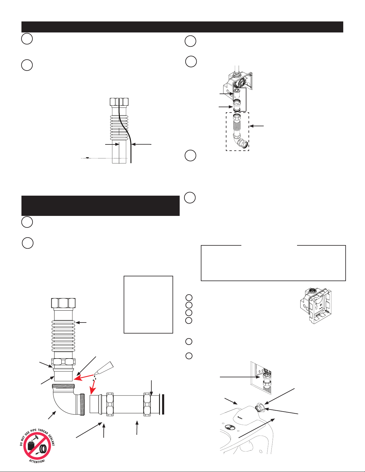
INSTALL OPTIONAL SWEAT SOLDER ADAPTER (ONLY IF YOUR SUPPLY PIPE DOES
NOT HAVE A MALE THREAD)
BRemove mud plate from valve and save for later use-DO NOT
DISCARD
CInsert sweat adapter into 1 1/2” to 1” threaded adapter (provided).
DConnect 1 1/2” to 1 “ adapter into top of ushometer (“IN”), Tighten
ttings securely into valve body with a xed jaw wrench.
NOTE: DO NOT EXERT FORCE ON WALL BOX TO TIGHTEN
FLUSHOMETER. USED FIXED JAW WRENCH TO HOLD THE
VALVE.
For hardwire
use only:
remove wall
box knock/
cap closest
to the conduit
connection.
FUsing a sweat union (not supplied), connect valve assembly to water
supply pipe.
Water Supply
Sweat Union
(not supplied) Sweat Connections
E
15”-18”
C
D
THREADED
SWEAT ADAPTER
PIPE
AOn a 15”-18” length of pipe (not provided), slide threaded sweat
adapter (not provided) onto water supply pipe until end of pipe rests
against shoulder of adapter. Sweat solder the adapter to pipe
(1" copper x 1" NPT tting).
NOTE: PROPERLY BRACE SUPPLY PIPE AFTER
SWEATING CONNECTIONS TO PREVENT VALVE
MOVEMENT DURING INSTALLATION AND USE
SLOAN RECOMMENDS BRACING VALVE WITHIN 6"
OF INLET CONNECTION.
6
CONFIGURE VACUUM BREAKER AND FLUSH CONNECTION AND CONNECT TO VALVE
AIf needed, trim bottom of adjustable tube using grinding style cut-off
tool
• NOTE: would only be needed for certain ADA
water closet installations.
• Consult rough-in guide (page 2-3)
As needed based on rough-in, pre-bend the adjustable tube to
account for side-to-side misalignment of water supply pipe relative
to xture spud.
B
C
D
Cut F-1 ush connection to length as needed for particular rough-in.
• Consult rough-in
Connect F-1 ush connection and adjustable tube to the elbow
using coupling and poly washer. Apply Loctite to tube ends,
insert tube ends into elbow, and tighten coupling securely (Do not
apply Loctite to coupling threads.
A
Cut as needed
B
Adjustable
Tube
Coupling
nut
Poly washer
Elbow
Taper towards
elbow
Poly washer
Taper towards
elbow F-1 Flush Connection
Coupling nut
EInsert V-651A vacuum breaker kit into vacuum breaker casing.
Attach to valve hand tight.
Attach ush connection to vacuum breaker.
F
GFor hardwire use only: insert conduit and tightly secure it to the wall
box. Run transformer wires through the conduit to the wall box.
NOTE: TRANSFORMER NOT PROVIDED. IT IS VERY
IMPORTANT THAT THE OUTPUT VOLTAGE OF THE
TRANSFORMER BE 6VAC FOR THE UNIT TO FUNCTION
PROPERLY. SLOAN EL-386 OR EL-451 IS RECOMMENDED.
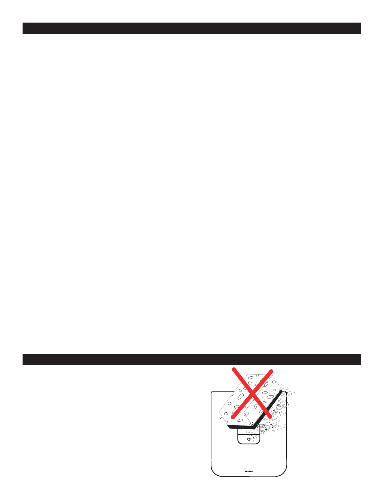
Finish wall. Use supplied mud guard to protect valve during nishing
process.
• Use two (2) mounting screws, if needed, to hold mud
guard to wall box
• Use the marks on mud guard to make sure nished wall
is between 3 ¼” and 4 ¼” from the center line of the pipe.
Vacuum Breaker
V651A Kit
Vacuum Breaker
casing
Flush Connection
Loosen vacuum breaker to valve.
Partially mount xture onto carrier bolts.
Pull ush connection forward through wall.
Make spud connection wrench tight.
• NOTE: Space permitting or chase present, spud
connection can be made behind wall.
Push xture back to wall. Tighten carrier bolts and complete
xture installation.
Re-connect vacuum breaker to valve.
I
J
K
L
M
N
I, N
J
M
L
K
FOR WALL HUNG REAR SPUD FIXTURES
(WATER CLOSETS)
H
NOTE:
Do not trim tube before pre-bending
V500A RB
Loctite must cure
for 24 hours before
turning on water
otherwise the
Loctite will wash
out and joint will
leak
Wall plate opening must be a minimum 7-3/8” wide x
8-3/8” tall (187 mm wide x 213 mm tall) to maximum
7-5/8” wide x 8-5/8” tall (194 mm wide x 219 mm tall)
Valve must be centered within opening.
!!! IMPORTANT !!!

Loosen vacuum breaker to valve.
Mount xture
Pull ush connection forward through wall.
Pre-install escutcheon and ttings in the following order:
1. Wall trim plate
2. Coupling
3. Friction ring
4. Gasket
5. Escucheon
Connect coupling (2) to spud, wrench tight.
Slide wall trim plate against wall.
Re-connect vacuum breaker to valve.
H
5 4 32 1
7
FOR REAR SPUD URINALS
F, L
F
G
H
I
J
K
L
FOR FLOOR MOUNT REAR SPUD FIXTURES (WATER CLOSET)
Adjustable Tube
Coupling
nut
Poly washer
Elbow
Taper towards
elbow
Coupling nut
A
B
Cut F-1 ush connection to length as needed for particular rough-in.
• Consult rough-in
Connect F-1 ush connection and adjustable tube to the elbow
using coupling and poly washer. Apply Loctite to tube ends,
insert tube ends into elbow, and tighten coupling securely (Do not
apply Loctite to coupling threads).
F-1 Flush Connection
Poly Washer
CInsert V-651 vacuum breaker kit into vacuum breaker casing.
Attach to valve hand tight.
Attach ush connection to vacuum breaker.
D
EFor hardwire use only: insert conduit and tightly secure it to the wall
box. Run transformer wires through the conduit to the wall box.
NOTE: TRANSFORMER NOT PROVIDED. IT IS VERY
IMPORTANT THAT THE OUTPUT VOLTAGE OF THE
TRANSFORMER BE 6VAC FOR THE UNIT TO FUNCTION
PROPERLY. SLOAN EL-386 OR EL-451 IS RECOMMENDED.
Finish wall. Use supplied mud guard to protect valve during nishing
process.
• Use two (2) mounting screws, if needed, to hold mud
guard to wall box
• Use the marks on mud guard to make sure nished wall
is between 3 ¼” and 4 ¼” from the center line of the pipe.
Vacuum Breaker
V-651-A Kit
Vacuum Breaker
casing
Flush Connection
Wall
opening
If needed, trim urinal ush tube.
Slide 3/4" coupling over urinal ush tube.
If cutting tube, thread adapter rst, then cut. After
cut, remove adapter to help chase/clean threads.
Thread F-28 brass ange onto urinal ush tube.
Amount of thread engagement will depend on rough-in.
Use provided Loctite to secure and seal F28 ange.
Apply Loctite to tube threads (completely around tube)
where ange will sit on tube. Then thread ange into Loctite.
Ensure Loctite is visible on both sides of ange. Allow time
for Loctite to "set", approx. 30 minutes.Slide F2 coupling over
urinal connection tube, and then install urinal connection tube
to urinal spud and tighten spud coupling.
Secure urinal ush tube to elbow using
1-1/2” gasket.
B
C
B
C
B
C
Adjustable
Tube
Taper toward
elbow
Coupling nut
Coupling
nut
Poly
washer
Elbow
G. Finish wall. Use supplied mud guard to protect valve during nish-
ing process.
• Use two (2) mounting screws, if needed, to hold mud gaurd to
wall box.
• Use the marks on mud guard to make sure finished wall is
between 3 1/4" and 4 1/4" from the center line of the pipe.
Hang urinal on mounting bracket.
Loosen vacuum breaker to valve.
Make spud connection behind the wall.
Re-connect vacuum breaker to valve.
I, K
J
Loctite must cure for
24 hours before turning
on water; otherwise the
Loctite will wash out
and joint will leak.
V500A RB
Loctite must cure
for 24 hours before
turning on water
otherwise the
Loctite will wash
out and joint will
leak
F28 Flange
Loctite must cure
for 24 hours before
turning on water
otherwise the
Loctite will wash
out and joint will
leak
A
B
C
F
D
G
H
I
J
K
Wall plate opening must be a
minimum 7-3/8” wide x 8-3/8”
tall (187 mm wide x 213 mm
tall) to maximum 7-5/8” wide
x 8-5/8” tall (194 mm wide x
219 mm tall). Valve must be
centered horizontally within
opening.
!!! IMPORTANT !!!
Wall plate opening must be a minimum 7-3/8” wide x
8-3/8” tall (187 mm wide x 213 mm tall) to maximum
7-5/8” wide x 8-5/8” tall (194 mm wide x 219 mm tall).
Valve must be centered horizontally within opening.
!!! IMPORTANT !!!
Once lines are ushed clear, turn
activation assembly clockwise to
shut off water.
8
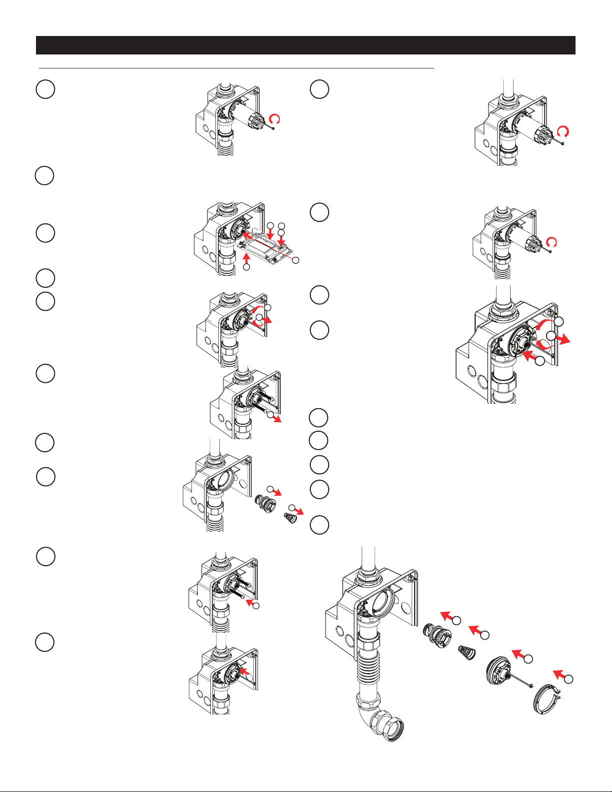
FLUSHING WATER LINES
Note: Valve is shipped with flow adjustment turned off. Requires sensor assembly.
AEnsure water is shut off:
use adjustment tool to turn
activation assembly fully
clockwise.Make sure solenoid
wire passes through center of
adjustment to avoid damage to
the cable.
BVerify valve is not pressurized
i. connect solenoid to sensor assembly.
ii. Connect battery pack.
iii. Press override button to
relieve pressure.
Disconnect Solenoid from Sensor
assembly. Pull on end connector
to prevent damage to wires.
Press in activation assembly.
ESqueeze tabs on Collar and pull
out.
FAttached provided 1/4-20 screws
to activation assembly. Pull to
remove assembly
R
Remove conical spring. Do not
discard!
Remove piston assembly by
pulling straight out. If unable to
grip piston, remove screw from
activation assembly and insert
into center hole of piston.
J
Reinstall activation assembly
and press until fully seated.
Remove screws.
CLOSE
G
H
G1
OPEN CLOSE
G
Reinstall Collar. Collar will
spin freely in valve body when
properly installed.
H
Using adjustment tool, turn activation
assembly counter clockwise to open
ow of water through the valve.
Push in activation assembly.
Squeeze tabs on Collar and pull
out.
I
K
M
L
Reinstall piston. Insert smaller sized end rst until fully seated.
Reinstall conical spring, small end rst, into piston.
Reinstall activation assembly and press until fully seated.
Reinstall orange collar securely. Collar will spin freely in valve body
when properly installed.
Adjust ow rate of valve as described in Section ADJUSTING FLOW
N
S
O
P
Q
CLOSE
E1
E2
B1
C
B3
D
B2
D
C
D
CLOSE
E1
E2
B1
C
B3
D
B2
D
CLOSE
E1
E2
B1
C
B3
D
B2
D
G
H
G1
OPEN CLOSE
G
H
G1
OPEN CLOSE
N2
N1
M
M
Q
R
O
P
N2
N1
M
M
Q
R
O
P
CLOSE
OPEN
9
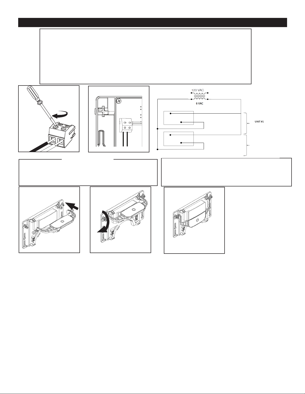
INSTALL WALL PLATE ASSEMBLY
For Hardwire connection use.
i. Using a wire stripper strip the two wire transformer connection from the conduit.
ii. Insert the wire to the Blue Terminal Block provided with the Sensor Assembly
iii. Tighten the terminal block screws using a athead screwdriver 0.118” (3 mm) or smaller.
iv. Connect the Blue terminal block to the two pins in the back of the Sensor Assembly.
IMPORTANT: SURGE PROTECTOR BEFORE THE TRANSFORMER IS RECOMMENDED
iii. iv.
One EL-386 Transformer (sold separately) serves one (1) CX Closet/
Urinal ushometer.
One EL-451 Transformer (sold separately) serves up to (6)CX Closet/
Urinal ushometer with 20 gauge wire within 50 feet
UNIT #2 THRU #10
(IF EL-451 USED)
THE SENSOR ASSEMBLY COMES WITH THE BUTTON
ALREADY INSTALLED. IN CASE THE BUTTON HAS COME
OFF FROM THE SENSOR ASSEMBLY DURING SHIPMENT,
INSTALL IT FOLLOWING THE FIGURE BELOW.
!!! NOTE !!!
Sloan CX
Sloan CX

10
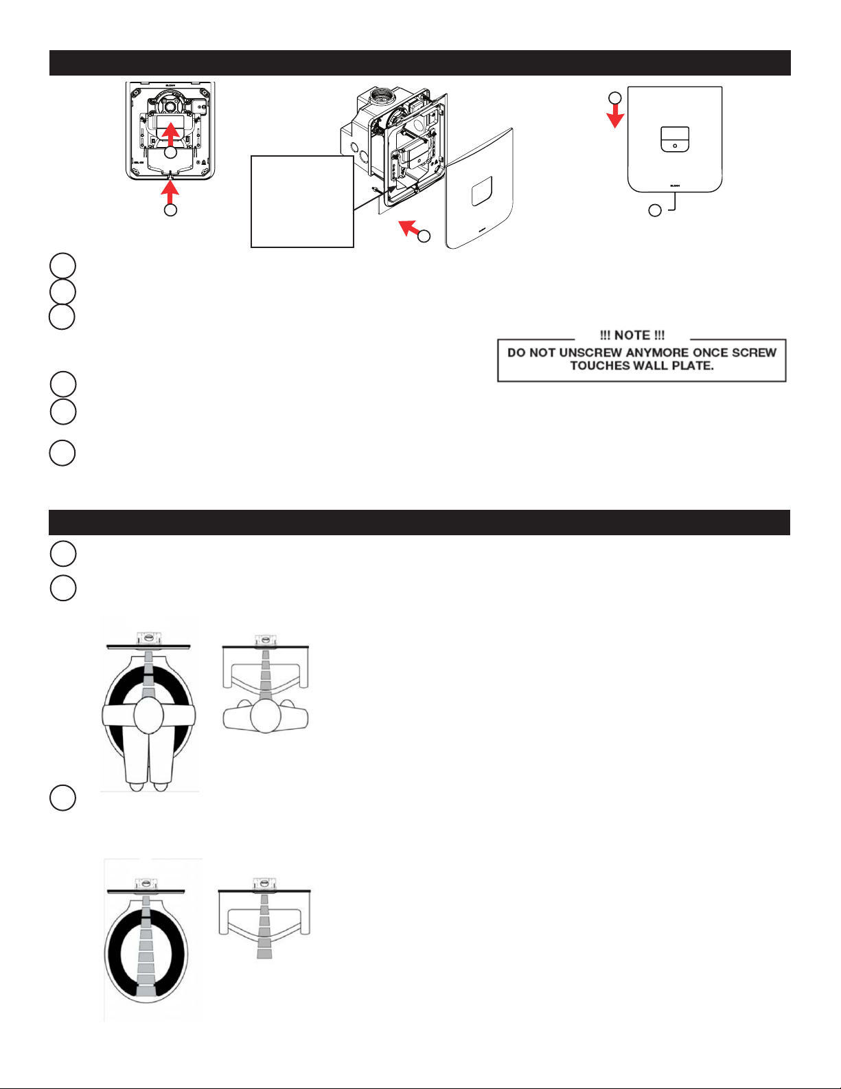
INSTALL WALL PLATE ASSEMBLY (CONT.)
A
B
B
C
D
Assemble C-Bracket to the wall bracket using two (2) 2” long
#8-32 screws.
Tighten two (2) locking nuts to the screws about ¼” away from tail
of the screws.
A
Rotate wall bracket slightly about vertical axis and slide C-Bracket
behind the nished wall while holding the top of the wall bracket.
Once C-bracket is behind the wall, align top two (2) holes on the
bracket to the wall box and secure in place using two (2) 2” long
#8-32 screws. Tighten the bottom two (2) screws on the bracket.
Make sure the wall bracket is positioned plumb and level before
tightening the screws completely.
The Sloan CX sensor assembly is designed to work with both
hardwire and battery as a back-up or only the battery power
connection
INSERT SOLENOID
CONNECTOR HERE
D
Connect Battery Box D-shape connector to Sensor assembly.
NOTE: RED LED WILL START BLINKING WHEN POWER IS
CONNECTED TO THE SENSOR ASSEMBLY.
Mount the Sensor Assembly to the wall bracket.
i. Aligned the four (4) slots on the sensor assembly with the
mounting pegs on the wall bracket.
ii. Slide the sensor Assembly all the way down.
G
Insert ushometer solenoid connector to the sensor assembly.
F
INSTALL BATTERY BOX AND SENSOR ASSEMBLY
NOTE: Solenoid can only be installed in one orientation
WATER DOES NOT HAVE TO BE TURNED OFF TO REPLACE
BATTERIES. USE ALKALINE BATTERIES FOR PROPER UNIT
OPERATION.
Remove battery cover by loosening screw using a
Phillips head screwdriver.
Install four (4) Alkaline AA-size batteries into the battery box in the
orientation noted on the inside the battery box.
NOTE
CReinstall the battery cover and, using a screwdriver, tighten the screw
until the battery cover is tightly secure.
Insert the Battery Box on the right side of the ushometer as shown.
E
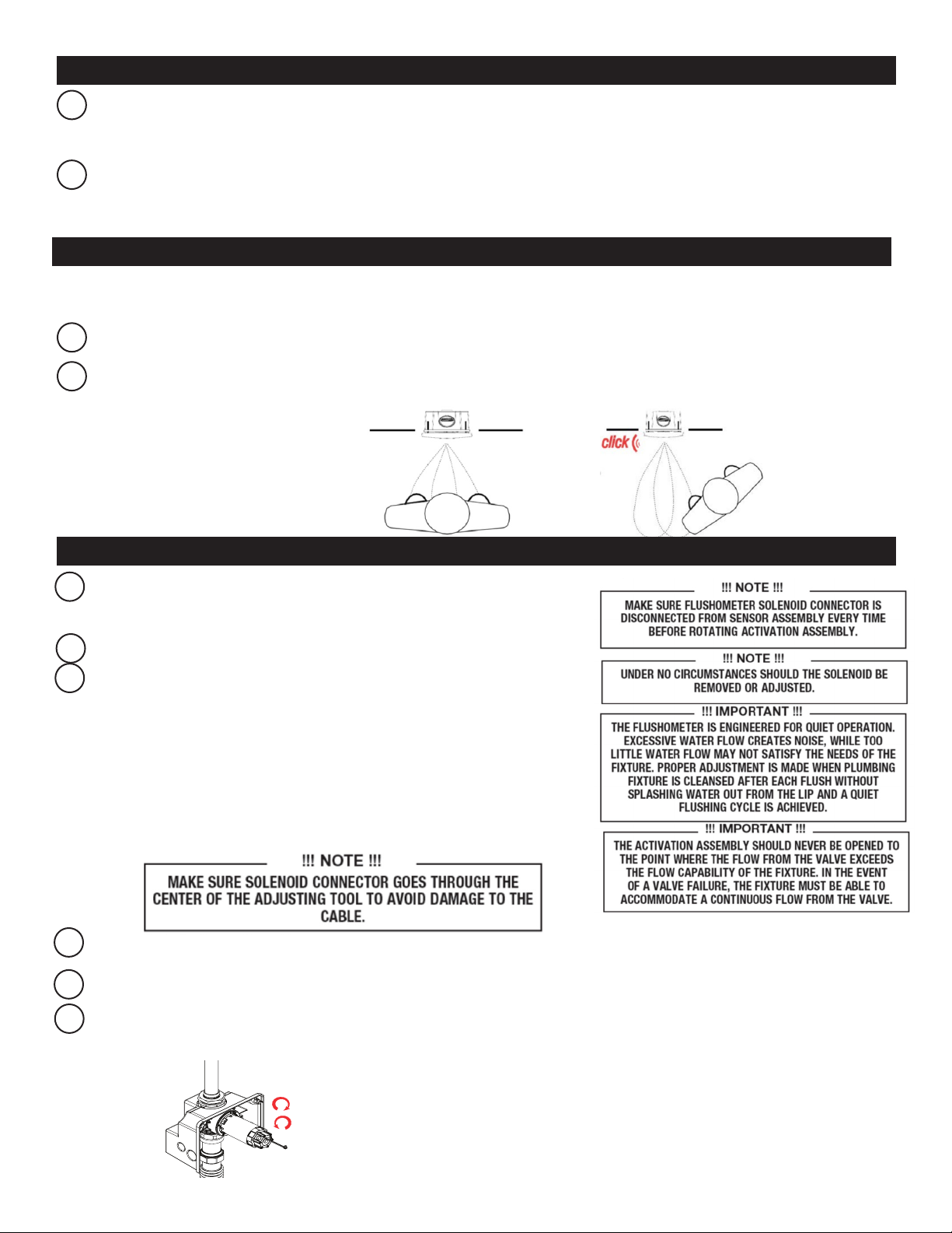
SENSOR OPERATION
After power is applied, the Sensor Module will perform its Start-up routine for approximately 3 minutes 30 seconds with LED blinking. Step
away from sensor during this
time. Sensor will calibrate without user in detection area to calibrate "non-use" enviroment.
NOTE: A one (1) second long Red LED, followed by one slow Red LED blinking in the Sensor Window indicates sensor is in the start-up mode.
There will be two (2) Red LED pulses (each two (1) second long) in the Sensor Window to indicate the start-up routine is complete.
After the start-up routine is complete, in the rst ten (10) minutes of operation, a visible Red LED ashes in the Sensor Window of the CX
Flushometer when a user is detected.
The CX Flushometer has a factory set sensing range:
i. Water Closet Models – 22” to 46” (559 mm to 1168 mm)
ii. Urinal Models – 15” to 34” 381 mm to 864 mm)
Test sensor by stepping in front of the sensor for 10 seconds.
After 10 seconds step away from the sensor and listen for a “CLICK”
The factory setting should be satisfactory for most installations. If a range adjustment is required, refer to the range adjustment instructions in this
installation guide (See page 13).
TEST SENSOR OPERATION
Flushometer is shipped with the ow control adjustment turned OFF.
Disconnect Flushometer Solenoid connector from the Sensor Assembly. Pull on end
connector to prevent damage to wires.
Lift the Sensor Assembly Override Button up to access the activation assembly.
Open water ow by turning activation assembly slowly COUNTERCLOCKWISE using
adjusting tool and a screwdriver or a wrench.
Connect Flushometer Solenoid connector to the Sensor Assembly.
Activate Flushometer by pressing the Override Button.
Adjust Activation Assembly after each ush until the ow rate
delivered properly cleanses the xture (turn CLOCKWISE to lessen
ow and COUNTERCLOCKWISE to increase ow).
A
B
A
B
C
A
B
D
E
F
CLOSE
OPEN
ADJUST WATER FLOW
11
i.There is approximately 1/8-turn (45°) of free spinning as the activation
assembly engages the shut-off sleeve between opening and closing
the valve.
ii. A 1-1/2" socket or wrench can be attached to the adjustment tool or
a screwdriver can be passed through the side side holes to provide
additional torque.
INSTALL WALL PLATE
Make sure retaining screw on bracket is fully tightened clockwise.
Slide Sensor Assembly all the way up.
Align Wall Plate cut out with the window and Override Button of Sensor Assembly and
push Wall Plate all the way in.
i.Make sure sensor window and button are sitting inside the wall plate cut out.
Slide Wall Plate all the way down.
Retaining screw is designed to rest inside the wall plate. Turning the retaining screw counter clockwise using supplied Allen key until it
touches wall plate will lock plate in place, preventing the plate from sliding upward and being removed.
Make sure Wall Plate doesn’t slide up.
A
B
C
OPERATION
A continuous, INVISIBLE light beam is emitted from the Sloan CX Sensor.
After the user enters the beam’s effective range, 22 to 46 inches (559 mm to 1168 mm) for closet installations and 15 to 34 inches (381 mm to
864 mm) for urinal installations for ten (10) seconds the ushometer is armed.
A
B
When the user steps away, the sensor initiates a “one-time” signal that activates the ushing cycle to ush the xture (1 second delay for urinal,
3 seconds delay for closet). The Circuit automatically resets and is ready for the next user.
C
A
B
D
E
C
A
B
D
E
C
A
B
D
E
C
D
E
F
12
NOTE: If desired,
orange flow
adjustment tool
can be stored
here.

RESTART SENSOR (ONLY IF NECESSARY)
The Sloan CX Flushometer has a factory set sensing range:
Water Closet Models - 22” to 46” (559 mm to 1168 mm)
Urinal Models - 15” to 34” (381 mm to 864 mm)
The Factory setting should be satisfactory for most installations. If the range is too short (i.e. not picking up users) or too long (i.e., picking up
opposite wall or stall door) the range can be adjusted.
NOTE: WATER DOES NOT HAVE TO BE TURNED OFF TO ADJUST RANGE.
Make sure to remove all the non-permanent targets in sensor view area.
Push Override button for 20-30 seconds.
The Red LED in the sensor window starts slow blinking.
Release the button during the LED blinking and step away.
The CX will enter into start-up mode.
The setting mode will run for one minute.
A
B
C
D
E
F
BASIC SERVICING
A. Remove wall plate.
Note: water can be shut-off without removing plastic mounting plate. Removal of plastic mounting plate provides more hand room for servicing valve
and accessing ush connection.
i. Turn the retaining screw at the bottom of wall plate using Allen Key clockwise
ii.Slide wall plate up, then pull out.
B. Disconnect ushometer solenoid connector from the sensor assembly. Pull on end connector to prevent damage to wires.
C. Shut off water: use adjustment tool to turn activation assembly fully clockwise. Pass solenoid wire through center of tool to avoid damage. Remove
tool when closed.
D. Reconnect the sensor assembly to the solenoid. Press override button to relieve pressure. Disconnect solenoid. Pull on end connector to prevent
damage to wires.
E. Push in activation assembly until fully seated.
F. Squeeze tabs on Collar and pull out.
G. Attach provided screws to activation assembly. Pull to remove assembly.
DO NOT TURN THE ASSEMBLY TO AVOID TURING WATER FLOW BACK ON. DO NOT REMOVE OR ADJUST THE
SOLENOID.
H. Remove conical spring. Do not discard!
I. Remove piston assembly by pulling straight out. If unable to grip piston, remove screw from activation assembly and insert
into center hole of piston.
J. Reinstall or replace piston. Insert smaller sized end rst until fully seated.
K. Reinstall or replace conical spring, small end rst, into piston.
L. Reinstall or replace activation assembly and press until fully seated.
M. Reinstall orange safety ring securely. Safety ring will spin freely in valve body when properly installed. NOTE: using screws attached to activation
assembly, pull activation assembly forward to ensure proper alignment.
N. Using adjustment tool, slowly turn the activation assembly counterclockwise to open ow.
O. Adjust ow as described on page 11.
P. Install wall plate as described on page 12.
13
TROUBLESHOOTING
CARE AND CLEANING
DO NOT use abrasive or chemical cleaners (including chlorine bleach)
to clean Flushometers that may dull the luster and attack the chrome or
special decorative nishes. Use ONLY mild soap and water, then wipe dry
with clean cloth or towel. While cleaning the bathroom tile, protect the
Flushometer from any splattering of cleaner. Acids and cleaning uids will
discolor or remove chrome plating.
A. Sensor Flashes Continuously Only When User Steps Within Range.
i. Unit in Start-Up mode; no problem. This feature is active for the rst ten (10) minutes of operation.
B. Valve Does Not Flush; Sensor Not Picking Up User.
i. Range too short; increase the range.
C. Valve Does Not Flush; Sensor Picking Up Opposite Wall or Surface, or Only Flushes When Someone Walks By.
Red Light Flashes Continuously for First 10 Minutes Even with No One in Front of the Sensor.
i. Range too long; shorten range.
D. Valve Does Not Flush Even After Adjustment.
i. Ensure water supply to valve is turned on.
ii. Activation Assembly sleeve is in closed position. Turn counterclockwise to open water ow. NOTE: there is approximately 1/8-turn (45°) of free
spinning as the activation assembly engages the shut-off sleeve between opening and closing the valve.
iii. Batteries completely used up; replace batteries.
iv. Problem with activation assembly; replace activation assembly.
v. Problem with Sensor Assembly; replace Sensor Assembly.
E. Red Light Blinks four (4) Times When User Steps Within Range (Battery Only).
i. Batteries low; replace batteries.
F. Red Light Blinks four (4) Times When User Steps Within Range (Hardwire and Battery).
i. Battery box not connected; connect battery box to sensor assembly.
ii. Batteries low; replace batteries.
G. Valve Does Not Shut off.
i. Metering bypass hole in piston is clogged. Remove the piston O-ring from groove and wash under clean running water.
Replace piston if cleaning does not correct the problem.
ii. Supply line water pressure has dropped and is not sufcient to close the valve. Close Activation Assembly until pressure is
restored. NOTE: under some conditions, opening the shut-off sleeve can correct the force imbalance and cause the valve close.
iii. Piston is damaged. Replace with new proper gpf/Lpf piston.
iv. Solenoid latched in open position during valve shipment. Connect sensor assembly and press override button. See "install battery box and sensor
assembly" section on page 10 for additional information.
H. Too much water to Fixture.
i. Activation Assembly not adjusted properly. Readjust Activation Assembly.
ii. Piston is damaged. Replace with new proper gpf/Lpf piston
iii. Wrong CX model installed; i.e.,1.6 gpf. model installed on 0.5 gpf/1.9 Lpf or 0.25 gpf/1.0 Lpf urinal xture. Replace
with proper CX model per guide.
I. Not enough water to Fixture.
i. Activation Assembly not adjusted properly. Readjust Activation Assembly by turning counterclockwise.
ii. Wrong CX model installed; i.e. 0.5 gpf. urinal installed on 1.6 gal. closet xture. Replace with proper CX model.
iii. Water supply pressure is inadequate (low). Increase the water supply pressure. Contact the xture manufacturer for
minimum water supply requirements of the xture.
J. Chattering noise is heard during flush.
i. Reduce ow pressure by turning Activation Assembly.
ii. Air trapped inside the valve and/or supply pipe. Air takes time - both count of ushes and actual duration-to be fully removed.
14
2
1
Item No. Part No. Description
1Consult Factory Piston Assembly
2See Table Activation Assembly
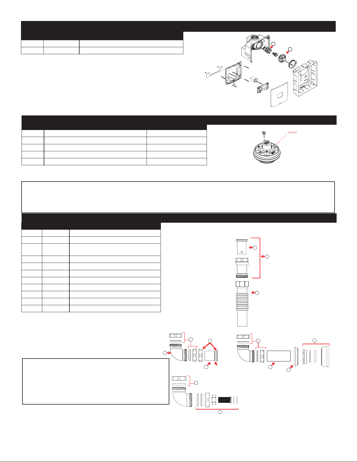
VALVE ASSEMBLY GUIDE
15
Code No. Description Plug Color*
3340057 1.6 gpf/6.0 Lpf closet activation assembly Green
3340058 1.28 gpf/4.8 Lpf closet activation assembly Purple
3340059 0.5 gpf/1.9 Lpf urinal activation assembly Red
3340060 0.25 gpf/1.0 Lpf urinal activation assembly Burgundy
33400006 0.125 gpf/0.5 Lpf urinal activation assembly Not Applicable
ACTIVATION ASSEMBLY SELECTION GUIDE
* Colors may differ. Consult factory to conrm you have the correct activation assembly.
Item Code No. Description
13323182 V-651 Vacuum Breaker Repair Kit
2 0323279 V500A RB Short Vacuum Breaker Assembly
30306391
0306367
Adjustable Tube for Wall Hung Closets and Urinals
Adjustable Tube for Floor Mount Closets
4 0306395 CX Poly Washer Coupling (set of 2)
5 0306392PK F-305 CX Elbow For CX Poly Washer
6 0306091 F-2-A 1-1/2" Coupling with S-21 Gasket
7 0306031PO F-1 1 1/2" (38 mm) Flanged outlet tube RB, 6"
8 0396669PK F-102 1-1/2" (38 mm) Outlet Tube CP 8"*
9 0306237PK F-7 Flange 1 1/2" x 3" w/Prongs, CP*
10 0306146PK F-5-A 1-1/2" Spud Coupling Assembly CP*
11 0306396 CX Urinal Connection
FLUSH CONNECTION PARTS
The information contained in this document is subject to change without notice.
Manufactured in the U.S.A by Sloan Valve Company under one or
more of the following patents: U.S. Patents. 5,295,655; 5,542,718;
5,558,120; 5,564,460; 5,730,415; 5,865,420; 5,887,848;
5,967,182. Other Patents Pending.
Bak-Chek®, Para-flo®, PERMEX®, Turbo-Flo®
* Consult factory for alternate nish options
IN ORDER FOR THE WATER CLOSET AND THE URINAL TO PERFORM PROPERLY FOR ITS INTENDED USE, YOU MUST FOLLOW THESE INSTRUCTIONS:
A. IDENTIFY YOUR FLUSHOMETER MODEL NO.
B. CHECK FOR THE WATER CONSUMPTION LABEL ATTACHED TO THE FLUSHOMETER AND FIXTURE, ENSURING THEY MATCH
C. REFER TO SPECIFIC FLUSHOMETER SECTION IN GUIDE FOR APPROPRIATE REPLACEMENT PART NO.
SLOAN VALVE COMPANY • 10500 SEYMOUR AVENUE • FRANKLIN PARK, IL 60131
Phone: 1.800.982.5839 or 1.847.671.4300 • Fax: 1.800.447.8329 or 1.847.671.4380 • sloan.com
COPYRIGHT © 2020 SLOAN VALVE COMPANY Code No: 0816858 – Rev. 3 (07/20)
Tech Support: 1.888.756.2614 or 1.888.SLOAN14
1
2
3
410
5
4
8
7Install with
Flange against spud
For Model 8158, Wall Hung For Model 8154, Floor Mount
9
4
For Model 8198
11
6
For complete listing of items available for repair,
please consult Maintenance and Repair Guide.
Contact Technical Support for assistance.
1.888.756.2614 or 1.888.SLOAN14
This manual suits for next models
7
Table of contents
Other Sloan Measuring Instrument manuals

Sloan
Sloan CX Series User manual

Sloan
Sloan CX 158 Use and care manual

Sloan
Sloan CX Guide

Sloan
Sloan Royal Use and care manual

Sloan
Sloan TruFlush Use and care manual

Sloan
Sloan NAVAL Operating manual

Sloan
Sloan G2 Optima Plus Instruction sheet

Sloan
Sloan EBV-200-A SMOOTH User manual

Sloan
Sloan CX 8158 Use and care manual

Sloan
Sloan EL-750/Hardwired Use and care manual


