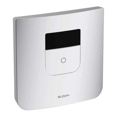
Sloan CX 8158 Use and care manual

Repair Parts and Maintenance Guide
CX Sensor Flushometer
Hardwired with Battery Backup
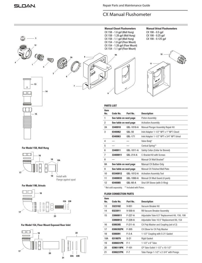
PARTS LIST
Item
No. Code No. Part No. Description
1See table on next page Piston Assembly
2See table on next page Activation Assembly (Includes Item 2A)
2A See table on next page Solenoid Assembly
30340062 GBL-56 Inlet Adapter 1-1/2” NPT x 1” NPT Closet
0340063 GBL-171 Inlet Adapter 1-1/2” NPT x 3/4” NPT Urinal
4——Sensor CX Valve Body and Box Assembly*
5——Conical Spring**
63340011 GBL-1011-A Safety Collar (Collar for Bonnet)
733400011 GBL-214-A C-Bracket with (2) Lock Nuts and Screws
8——Sensor CX Wall Bracket*
99103681PK ELG-79 Battery Pack
10 See table on next page Sensor Assembly Closet
See table on next page Sensor Assembly Urinal
11 See table on next page Finished Wall Plate
11A See table on next page Override Button Only
12 3340012 GBL-1012-A Activation Assembly Tool
13 33400035 GBL-1062-A Replacement Mud Guard, Sensor (4 pack)
14 0340085 GBL-66-A Shut Off Sleeve (with O-Ring)
* Not sold separately. ** Included with Piston.
FLUSH CONNECTION PARTS
Item
No. Code No. Part No. Description
15 3323183 V-651 Vacuum Breaker Repair Kit
16 0323011 V-500-A RB Vacuum Breaker Assembly
17 33060011 F-227-A Adjustable Tube 6.5” Replacement Kit, 8158,
8198
33060012 F-228-A Adjustable Tube 10.5” Replacement Kit, 8154
18 0306395 F-211-A CX Poly Washer and Coupling (set of 2)
19 0306392PK F-305 CX Elbow for CX Poly Washer
20 0306091 F-2-A 1-1/2” Coupling Set with S-21 Gasket
20A 0319079 S-21 1-1/2" Rigid Gasket
Sensor Closet Flushometers
CX 8158 - 1.6 gpf (Wall Hung)
CX 8158 - 1.28 gpf (Wall Hung)
CX 8158 - 1.1 gpf (Wall Hung)
CX 8154 - 1.6 gpf (Floor Mount)
CX 8154 - 1.28 gpf (Floor Mount)
CX 8154 - 1.1 gpf (Floor Mount)
Sensor Urinal Flushometers
CX 8198 - 0.5 gpf
CX 8198 - 0.25 gpf
CX 8198 - 0.125 gpf
15
16
17
18
For Model 8158, Wall Hung
19
20
21 Install with
Flange against spud
For Model 8198, Urinals
18
25
For Model 8154, Floor Mount Exposed Rear Inlet
18
22
23
24
20A
25A 25B
19
19
24A 24B
1
2
3
4
5
6
7
8
9
10
11A
11
12
13
14
2A

Repair Parts and Maintenance Guide
CX Sensor Flushometer
Hardwired with Battery Backup
ITEM NO. 1 - SENSOR PISTON ASSEMBLY SELECTION GUIDE
Code No. Part No. Description
Piston
Color*
3340053 GBL-1037-A 1.6 gpf/6.0 Lpf Closet Piston Assembly Green
33400079 GBL-1098-A 1.28 gpf/4.8 Lpf Closet Piston Assembly Blue/Black
33400061 GBL-1088-A 1.1 gpf/4.2 Lpf Closet Piston Assembly Burgundy/
Black
3340055 GBL-1039-A 0.5 gpf/1.9 Lpf Urinal Piston Assembly Red
3340056 GBL-1040-A 0.25 gpf/1.0 Lpf Urinal Piston Assembly Burgundy
33400003 —0.125 gpf/0.48 Lpf Urinal Piston Assembly†Red/Pink
ITEM NO. 2 - ACTIVATION ASSEMBLY SELECTION GUIDE
LEGACY CONNECTION** - PRIOR TO DECEMBER 2021
Code No. Part No. Description Plug Color*
3340057 GBL-1041-A 1.6 gpf/6.0 Lpf Closet Activation Assembly,
Legacy connection
Green
3340058 GBL-1042-A 1.28 gpf/4.8 Lpf Closet Activation
Assembly, Legacy connection
Purple
3340059 GBL-1043-A 0.5 gpf/1.9 Lpf Urinal Activation Assembly,
Legacy connection
Red
3340060 GBL-1044-A 0.25 gpf/1.0 Lpf Urinal Activation
Assembly, Legacy connection
Burgundy
33400006 GBL-1070-A 0.125 gpf/0.48 Lpf Urinal Activation
Assembly, Legacy connection
N/A; Nickel
plated brass
PIGTAIL CONNECTION** - AFTER DECEMBER 2021
Code No. Part No. Description Plug Color*
33400051 GBL-1077-A 1.6 gpf/6.0 Lpf Closet Activation Assembly,
Pigtail connection
Green
33400052 GBL-1078-A 1.28 gpf/4.8 Lpf Closet Activation
Assembly, Pigtail connection
Purple
33400062 GBL-1092-A 1.1 gpf/4.2 Lpf Closet Activation Assembly Grey
33400053 GBL-1079-A 0.5 gpf/1.9 Lpf Urinal Activation Assembly,
Pigtail connection
Red
33400054 GBL-1080-A 0.25 gpf/1.0 Lpf Urinal Activation
Assembly, Pigtail connection
Burgundy
33400056 GBL-1081-A 0.125 gpf/0.48 Lpf Urinal Activation
Assembly, Pigtail connection
N/A; Nickel
plated brass
* Colors may differ. Consult factory to confirm you have the correct assembly.
** Includes Solenoid Repair Kit #2A.
NOTE: Item No. 1 includes Item No. 5 (Conical Spring).
*Colors may differ. Consult factory to confirm you have the correct Piston Assembly.
†0.125 gpf/0.48 Lpf Valve Components (Piston, Main Seat, and Activation Assembly)
are NOT interchangeable with any other flush volume Valves.
PLUG
CONNECTION TYPES
PIGTAIL
LEGACY
2
WIRE
SOLENOID
FLUSH CONNECTION PARTS CONTINUED
Item
No. Code No. Part No. Description
21 0306031PK F-1 1-1/2” x 6” Tube
22 0396119PK F-101 CP Tube Outlet 1-1/2” x 10-1/2”
23 0306237PK F-7 Tube Flange 1-1/2” x 2-3/4” with Prongs
24 0306146 F-5-AT 1-1/2” Spud Coupling Assembly CP *
24A 5306058 F-3 Friction Ring 1-1/2”
24B 5322001 VBF-5 Slip Joint Gasket 1-1/2”
25 0306396 —Urinal Flush Connection Repair Kit
25A 5306055 F-3 Red Friction Ring 3/4”
25B 5306113 F-5 Gasket 3/4”
ITEM NO. 2A - SOLENOID ASSEMBLY SELECTION GUIDE
Code No. Part No. Description
33250013 EBV-415-A Solenoid Assembly with Legacy connection
33400078 GBL-1096-A Solenoid Assembly with Pigtail connection
ADDITIONAL PARTS
Code No. Part No. Description
—F-304 Poly Washer 1-1/2” (Only available in F-211-A, Item 18)
33400019 GBL-1050-A Sensor CX Finished Wall Plate and Button Assembly, SF‡
33400021 GBL-1051-A Sensor CX Finished Wall Plate and Button Assembly, CP‡
33400022 GBL-1052-A Sensor CX Finished Wall Plate and Button Assembly, BN‡
33400023 GBL-1053-A Sensor CX Finished Wall Plate and Button Assembly, PB‡
33400024 GBL-1054-A Sensor CX Finished Wall Plate and Button Assembly, GR‡
33400025 GBL-1055-A Sensor CX Button Only Replacement Kit, SF
33400026 GBL-1056-A Sensor CX Button Only Replacement Kit, CP
33400027 GBL-1057-A Sensor CX Button Only Replacement Kit, BN
33400028 GBL-1058-A Sensor CX Button Only Replacement Kit, PB
33400029 GBL-1059-A Sensor CX Button Only Replacement Kit, GR
‡
Includes mounting screws and wrench.
ITEM NO. 10 - SENSOR ASSEMBLY SELECTION GUIDE
Code No. Part No. Description
0340271 GBL-209-AC CX Sensor Assembly for Closet with Legacy connection
0340272 GBL-210-AU CX Sensor Assembly for Urinal with Legacy connection
33400069 GBL-219-A CX Sensor Assembly for Closet with Pigtail connection
33400071 GBL-220-A CX Sensor Assembly for Urinal with Pigtail connection
NOTE: After December 2021, the Activation,
Solenoid, and Sensor Assembly connections
were changed to a pigtail style connection.
ITEM NO. 1 - SENSOR PISTON IDENTIFICATION CHART
Flush Volume 1.6 gpf
Water Closet
1.28 gpf
Water Closet
1.1 gpf
Water Closet
0.5 gpf
Urinal
0.25 gpf
Urinal
0.125 gpf
Urinal
Piston Body Green Light Blue Burgundy Red Burgundy Red
Flow Control Green Black Cage Black Cage Red Burgundy Pink
Part Number GBL-1037-A GBL-1098-A GBL-1088-A GBL-1039-A GBL-1040-A —
Code Number 3340053 33400079 33400061 3340055 3340056 33400003
FLOW
CONTROL
PISTON
BODY
PLUG
CONNECTION TYPES
PIGTAIL
LEGACY
2 WIRE
SOLENOID

Repair Parts and Maintenance Guide
TROUBLESHOOTING GUIDE
CX Sensor Flushometer
Hardwired with Battery Backup
1. Sensor LED Flashes Continuously Only When User Steps Within Range.
A. Unit is in start-up mode; no problem. This feature is active for the first ten (10) minutes of operation.
2. Red Light Blinks Four (4) Times When User Steps Within Range.
A. “AA” Batteries depleted; replace batteries, lithium or alkaline. Ensure batteries are installed with proper polarity (+) and (-). Do not mix old and new batteries or
different types.
B. (Hardwired) Battery Box not connected; connect Battery Box to Sensor Assembly.
3. Valve Does Not Flush; Sensor Not Picking Up User.
A. Verify a urinal Sensor is not used on a closet Valve. Model is marked on rear of Sensor.
B. Range is too short; recalibrate range. Restart the Sensor by holding the Override Button in for 25 seconds, then release the Override Button and step away for
one (1) minute; with power connected, this is considered a Soft Reset.
C. For Hard Reset of Sensor, remove all power connections (battery and hardwire) for one (1) minute. Reconnect power and step away from front of Sensor for 3½
minutes. Then test Sensor activation by standing in front of Sensor for ten (10) seconds, then step away and wait for flush. Test push button.
4. Valve Does Not Flush; Sensor Picking Up Opposite Wall or Surface, or Only Flushes When Someone Walks By.
Red Light Flashes Continuously for First 10 Minutes Even with No One in Front of the Sensor.
A. Verify a closet Sensor is not used on a urinal Valve. Model is marked on rear of Sensor.
B. Range is too long; recalibrate range. Restart the Sensor by holding the Override Button in for 25 seconds, then release the Override Button and step away for
one (1) minute; with power connected, this is considered a Soft Reset.
C. If range needs to be manually shortened, reset the Sensor (follow Step 3B) and stand in front of the Sensor at desired range distance for one (1) minute.
D. For Hard Reset of Sensor, remove all power connections (battery and hardwire) for one (1) minute. Reconnect power and step away from front of Sensor for 3½
minutes. Then test Sensor activation by standing in front of Sensor for ten (10) seconds, then step away and wait for flush. Test push button.
5. Valve Does Not Flush Even After Sensor Recalibration.
A. Ensure water supply to Valve is turned on.
B. Activation Assembly sleeve is in closed position. Turn counter-clockwise to open water flow. Note: there is approximately 1/8-turn (45°) of free spinning as the
Activation Assembly engages the Shut Off Sleeve between opening and closing the Valve.
C. Solenoid wire disconnected from Sensor. Ensure Solenoid wires are intact and Solenoid plug is connected properly.
D. “AA” Batteries depleted; replace batteries, lithium or alkaline. Ensure batteries are installed with proper polarity (+) and (-). Do not mix old and new batteries or
different types.
E. Sensor Assembly malfunctioned. Disconnect power for one (1) minute, reconnect power, and check for start-up operation (flashing red LED). See Step 4D.
F. Check Solenoid for activation (clicking noise when pressing Sensor Override Button). If no clicks are heard, then contact Technical Support.
6. Valve Does Not Shut Off.
A. Ensure Solenoid is connected to Sensor.
B. Supply line water pressure has dropped and is not sufficient to close the Valve. Close Activation Assembly until pressure is restored.
C. Piston Bypass is clogged, Piston is damaged, or large debris stuck behind Piston. Turn off water at Shut Off Sleeve, release pressure, remove Safety Collar and
Activation Assembly. Remove Piston and check inside Valve for large debris. Replace Piston if damaged or cleaning does not correct the problem.
7. Too Much Water to Fixture.
A. Excessive flow pressure. Readjust Activation Assembly by turning clockwise to decrease flow pressure.
B. Long Flush. Worn Piston; replace with new proper gpf/Lpf Piston.
C. Wrong model installed; i.e., 1.6 gpf model installed on 0.5 gpf/1.9 Lpf or 0.25 gpf/1.0 Lpf urinal fixture. Replace with proper model per guide.
8. Not Enough Water to Fixture.
A. Insufficient flow pressure. Readjust Activation Assembly by turning counter-clockwise to increase flow pressure.
B. Water supply pressure is inadequate (low). Increase the water supply pressure. Contact the fixture manufacturer for minimum water supply requirements of the
fixture.
C. Wrong model installed; i.e., 0.5 gpf/1.9 Lpf urinal installed on a 1.6 gpf/6.0 Lpf closet fixture. Replace with proper model.
D. Check lip seal for wear. Replace Piston if lip seal is worn or twisted.
9. Chirping Noise is Heard at the Start or End of Flush.
A. Caused by air purging from the system inside the Valve Assembly. Noise will subside with several flushes or within a day.
CARE AND CLEANING
DO NOT USE abrasive or chemical cleaners (including chlorine bleach) to
clean Flushometers that may dull the luster and attack the chrome or special
decorative finishes. Use mild soap and water, then wipe dry with a clean soft
cloth or towel. If using a cleaner in a spray bottle, DO NOT spray directly
onto the Flushometer, instead spray cleaner into a clean cloth and then wipe
down the Flushometer.
While cleaning surrounding bathroom tile, protect the Flushometer from
any splattering of cleaner. Acids and abrasive cleaning fluids will discolor or
remove chrome plating.
When assistance is required, please contact Sloan Technical Support at 1.888.SLOAN.14 (1.888.756.2614).
IMPORTANT NOTE FOR 1.1 GPF
FLUSHOMETERS & REPLACEMENT KITS
Sloan 1.1 gpf/4.2 Lpf ultra-high efficiency flushometers meets all applicable
standards and requirements. However, with low flush volumes it is imperative that
they only be used in conjunction with toilet fixtures and drain line systems designed
to operate with adequate flow rates and volumes in order to effectively eliminate
waste and move it out of the building. It is the responsibility of the user to ensure
both of these conditions are met. Not doing so may void your warranty.
Sloan 1.1 gpf diaphragm and piston kits are designed as a replacement part for
Sloan 1.1 gpf/4.2 Lpf flushometers only. They are not intended to be used as a
means to reduce water consumption in flushometers with higher flush volumes such
as 1.28 gpf/4.8 Lpf or 1.6 gpf/6.0 Lpf or higher. Using this kit in any manner other
than with a Sloan 1.1 gpf flushometer may void your warranty.
This manual suits for next models
2
Other Sloan Measuring Instrument manuals
Sloan
Sloan CX Series User manual
Sloan
Sloan G2 Optima Plus Instruction sheet

Sloan
Sloan Royal Use and care manual

Sloan
Sloan TRF 8156-1.28 User manual
Sloan
Sloan EBV-200-A SMOOTH User manual
Sloan
Sloan G2 Optima Plus Instruction sheet

Sloan
Sloan Optima User manual
Sloan
Sloan CX 8154-1.6 User manual
Sloan
Sloan CX Guide

Sloan
Sloan TruFlush Use and care manual
