SMART-AVI DVX-200 User manual
Other SMART-AVI Extender manuals
SMART-AVI
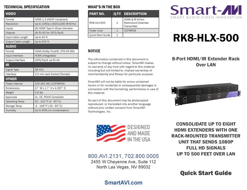
SMART-AVI RK8-HLX-500 User manual
SMART-AVI
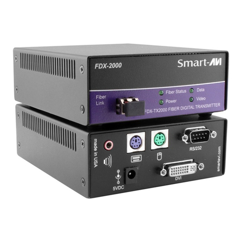
SMART-AVI FDX-2000 User manual
SMART-AVI
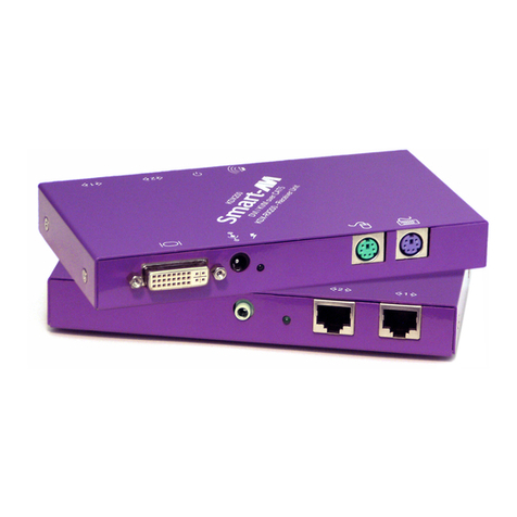
SMART-AVI KDX-200 User manual
SMART-AVI
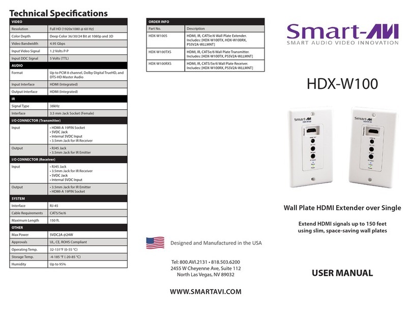
SMART-AVI HDX-W100S User manual
SMART-AVI
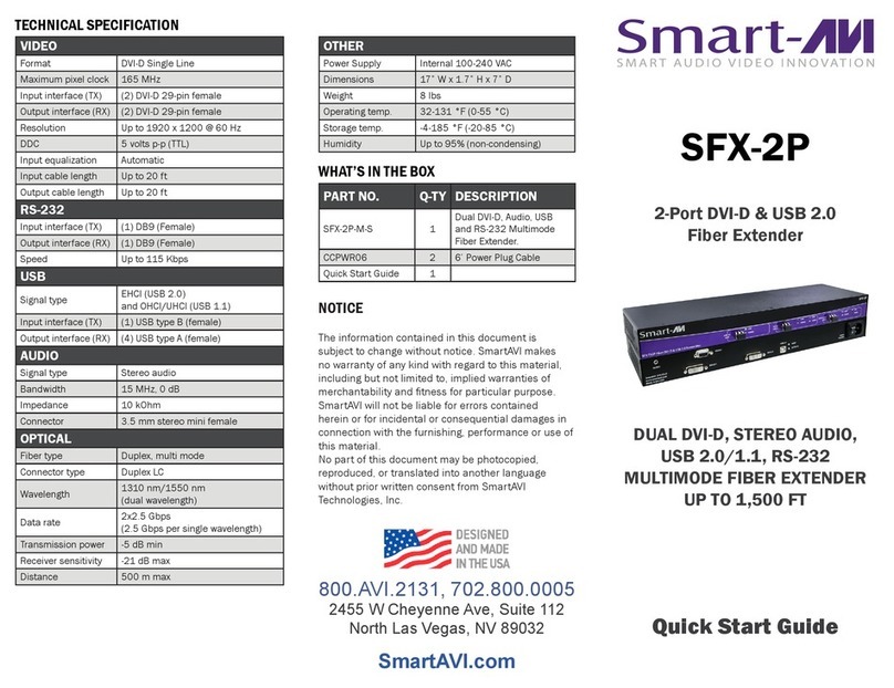
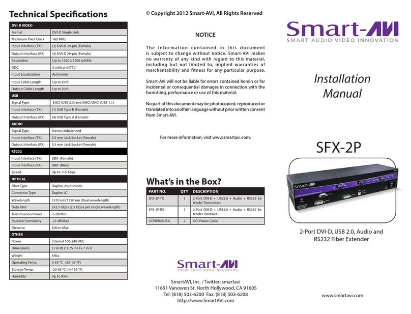
SMART-AVI SFX-2P User manual
SMART-AVI
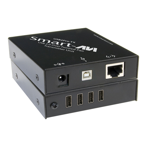
SMART-AVI USB2Pro User manual
SMART-AVI
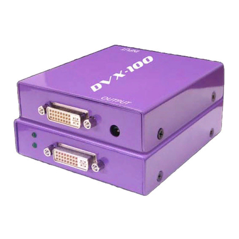
SMART-AVI DVX-100 User manual
SMART-AVI
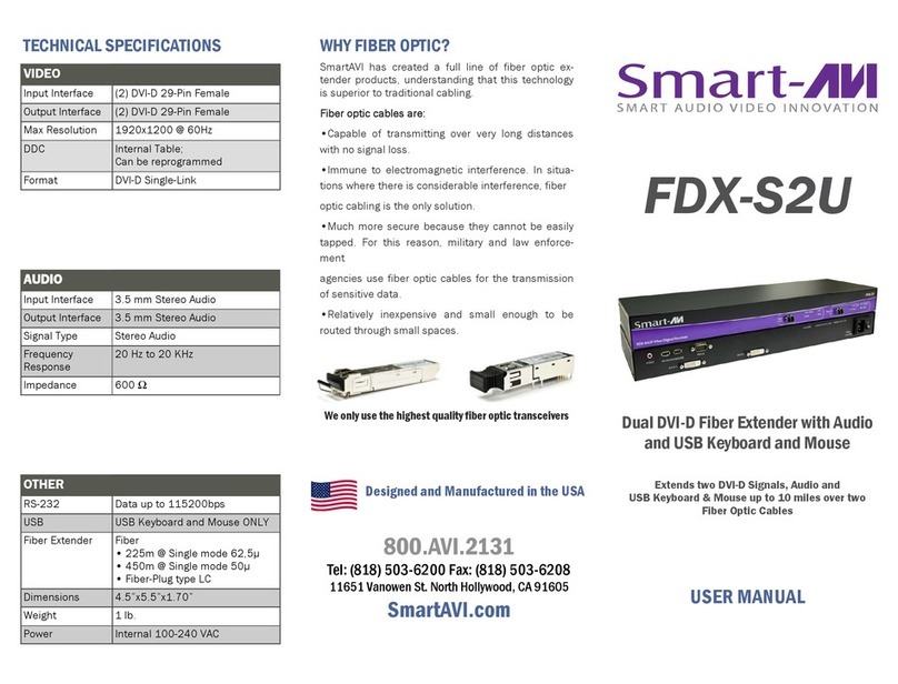
SMART-AVI FDX-S2U User manual
SMART-AVI
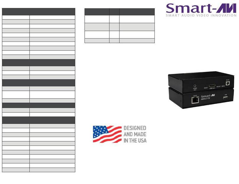
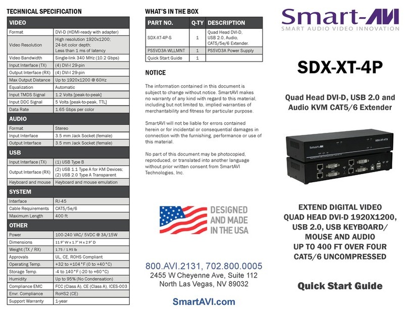
SMART-AVI HDX-LT User manual
SMART-AVI
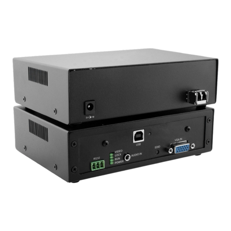
SMART-AVI SDX-XT-4P User manual
SMART-AVI
SMART-AVI FVX-3000-Pro User manual

SMART-AVI
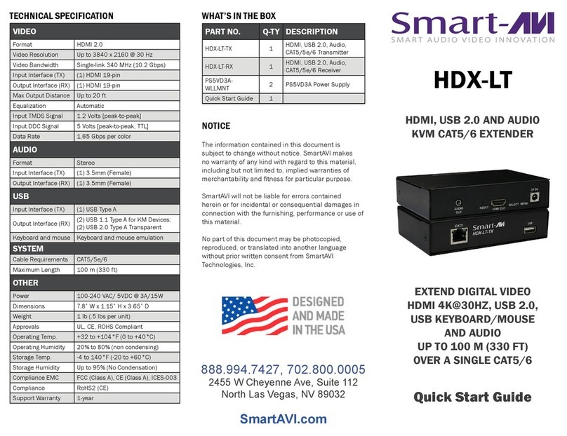
SMART-AVI DVX-RX200 User manual
SMART-AVI
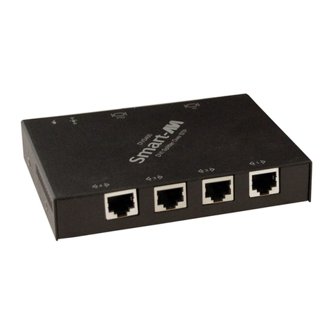
SMART-AVI HDX-LT User manual
SMART-AVI
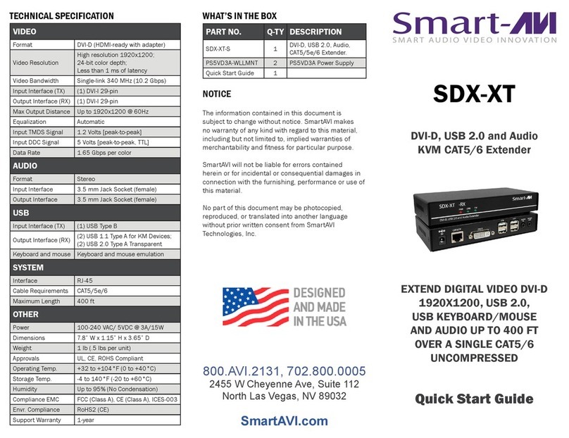
SMART-AVI DVS400 User manual
SMART-AVI
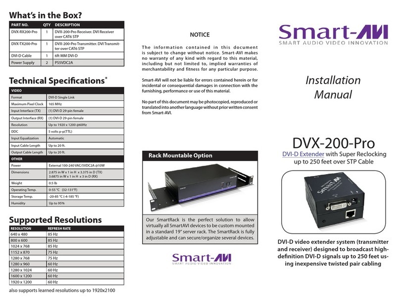
SMART-AVI SDX-XT User manual
SMART-AVI
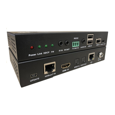
SMART-AVI DVX-200-Pro User manual
SMART-AVI
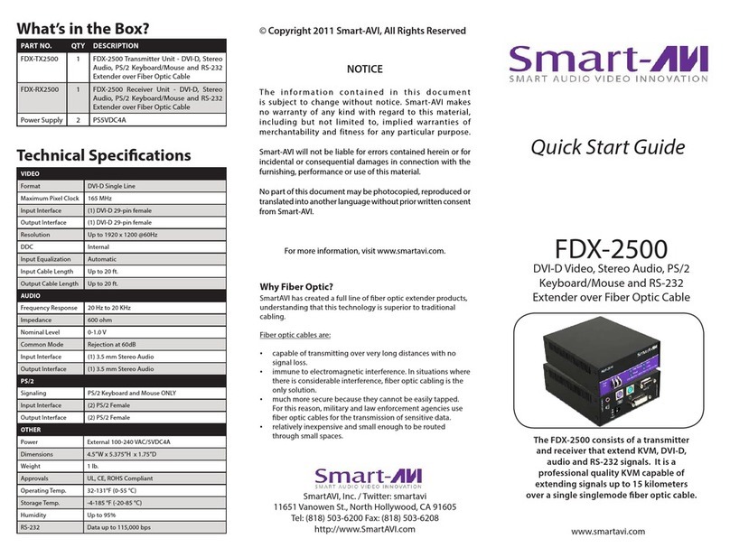
SMART-AVI HDX-XT User manual
SMART-AVI
SMART-AVI FDX-2500 User manual
SMART-AVI
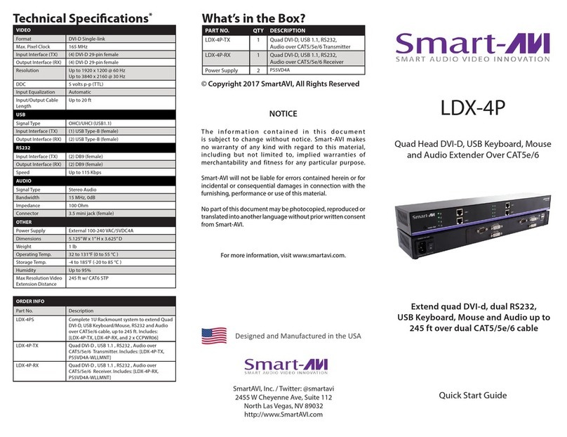
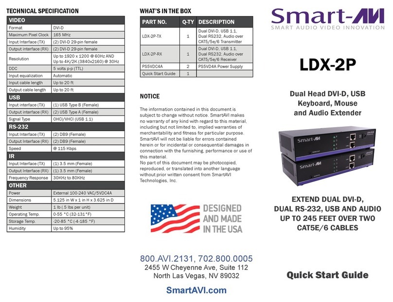
SMART-AVI LDX-2P User manual
SMART-AVI
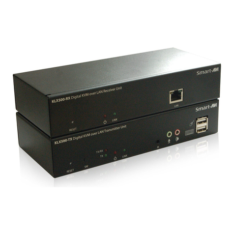
SMART-AVI KLX-500 User manual
Popular Extender manuals by other brands

foxunhd
foxunhd SX-AEX01 operating instructions

TERK Technologies
TERK Technologies LFIRX2 owner's manual

Devolo
Devolo Audio Extender supplementary guide

Edimax
Edimax EW-7438RPn V2 instructions

Shinybow USA
Shinybow USA SB-6335T5 instruction manual

SECO-LARM
SECO-LARM ENFORCER EVT-PB1-V1TGQ installation manual

