Smart power OFFICE Plus Series User manual

P.N.16001450 Rev.8/18
USER'S GUIDE
Uninterruptible
Power Supply
420VA - 850VA
Models:
Office-Plus TBF UPS Series
OFFICE Plus Series
OF420UPlus-T
OF650UPlus-T
OF850UPlus-T

1
Important Safety Instructions
Save These Instructions
This manual contains important instructions that should be followed during
installation and maintenance of the UPS and batteries. Please read and follow
all instructions carefully during installation and operation of the unit. Read this
manual thoroughly before attempting to unpack, install, or operate.
CAUTION! The UPS must be connected to a grounded AC power outlet with
fuse or circuit breaker protection. DO NOT plug the UPS into an outlet that is
not grounded. If you need to de-energize this equipment, turn off and unplug
the UPS.
CAUTION! The battery can energize hazardous live parts inside even when
the AC input power is disconnected.
CAUTION! To prevent the risk of fire or electric shock, install in a temperature
and humidity controlled indoor area, free of conductive contaminants. (Please
see specifications for acceptable temperature and humidity range).
CAUTION! To reduce the risk of electric shock, do not remove the cover. There
are no user serviceable parts inside. Refer servicing to qualified service
personnel.
CAUTION! To avoid electrical shock, turn off the unit and unplug it from the AC
power source before installing a computer component.
CAUTION! DO NOT USE WITH OR NEAR AQUARIUMS! To reduce the risk of
fire, do not use with or near aquariums. Condensation from the aquarium can
come in contact with metal electrical contacts and cause the machine to short
out.
CAUTION! DO NOT USE WITH LASER PRINTERS! The power demands of
laser printers are too large for a UPS.
WARNING!!
To reduce the risk of fire, replace only with same type of fuse.
Refer servicing to qualified service personnel only.
To reduce the risk of fire or electric shock, install in a temperature and
humidity controlled indoor area free of conductive contaminants.
Risk of Electric Shock. Battery circuit is not isolated from AC input,
hazardous voltage may exist between battery terminals and ground.

2
Important Safety Instructions
Save These Instructions
Unpacking
NOTICE!!!
The output of the Office 420 is not sinusoidal. It has a total harmonic
distortion of 61% and a maximum single harmonic distortion of 46.6%.
The output of the Office 650 is not sinusoidal. It has a total harmonic
distortion of 46% and a maximum single harmonic distortion of 33%.
UNPACKING
The box should contain the following:
(1) UPS unit with TBF™ Power Conditioner ;(2) User Guide ;
(3) USB Cable
OVERVIEW
The UPS ensures consistent power to your computer system and
its included software will automatically save your open files and
shutdown your computer system during autility power loss.
HOW TO DETERMINE THE POWER REQUIREMENTS OF YOUR
EQUIPMENT
1. Make sure that the total Volt-Amp (VA) requirements of your
computer, monitor, and peripheral equipment does not exceed rated
capacity.
2. Ensure that the equipment plugged into the battery power-
supplied/surge outlets does not exceed the UPS unit's rated capacity.
If the rated unit capacities are exceeded, an overload condition may
occur and cause the UPS unit to shut down or the circuit breaker to
trip.

System Description
1. Power On/Off Switch
2. Green LED: On AC Line Mode
Yellow LED: Battery Mode
Red LED: Fault
3. Battery power Plus Power Conditioning TBF™
Receptacles with battery power plus power conditioning (TBF™)
for critical devices that need to stay on when power goes out.
4. Power Conditioning TBF™ only
Receptacles with power conditioning (TBF™) only for non-critical
devices.
5. Input power cord
6. USB COMM. Port
7. Communication Protection Ports (RJ45 & RJ11)
8. Input Circuit Breaker
Green LED on Off Normal
Beeps every 30s
Beeps every 2s
Beeps every 0.5s
Beeps continuously
Yellow LED flash
3
LED ALARM CONDITION
Yellow LED flash
Red LED flash
Red LED on
Utility Failure - The UPS is providing battery power to outlets.
Utility Failure - The UPS is providing battery power.
The rapid beeps indicate the battery will run out of power shortly.
Overload - Occurs when connected equipment exceeds the
rating of the unit. Turn the UPS off and unplug at least one
piece of equipment from the UPS.
Fault -Occurs when the UPS Fail.Unplug the equipment and
restart the UPS or Contact Technical Support.
DEFINITIONS FOR ILLUMINATED LED INDICATORS

Troubleshooting
If the UPS failed to operate properly, please review the following:
The outlets stop
providing power to
equipment.Circuit
breaker button is
projecting from the
side of the unit
The UPS does not
perform expected
runtime.
The UPS will not
turn on.
The UPS will not
turn on.
Circuit breaker has
tripped due to an
overload
Battery not fully charged
Battery is slightly worn out
The on/off switch is
designed to prevent
damage by rapidly
turning it off and on
The battery is worn out
Mechanical problem
Turn the UPS off and
unplug at least one
piece of equipment.
Reset the circuit breaker
by depressing the button,
and then turn the UPS on
Recharge the battery
by leaving the UPS
plugged in
Contact Technical
Support.
Turn the UPS off. Wait
10 seconds and then
turn the UPS on
Contact Technical
Support
Contact Technical
Support
Symptom Possible Cause Solution
4

Installation and Operation
Installing the Office Series UPS is as easy as following the steps
shown. Be aware that the Power Switch must be kept in the "ON"
position and all equipment must be plugged into the "Battery Power
Supplied" receptacles. Otherwise the UPS will be disabled and your
equipment will not be protected during a power failure.
Inspection
Unpack the UPS carefully and note the packing method. Retain the box
and packing material for possible future shipment. Visually inspect the
UPS for freight damage. Report damage to the carrier and your dealer.
Placement
Install the UPS unit in any protected environment that provides adequate
airflow around the unit, and is free from excessive dust, corrosive fumes
and conductive contaminants. DO NOT operate your UPS in an
environment where the ambient temperature or humidity is high.
1
2
5
SmartPower
SYSTEMS
••••••••••••••••

Charging
This unit is shipped from the factory with its internal battery fully charged,
however, some charge may be lost during shipping and the battery
should be recharged prior to use. Plug the unit into an appropriate power
supply and allow the UPS to charge fully by leaving it plugged in for at
least 8-10 hours with no load (no electrical devices such as computers,
monitors, etc.) connected.
Computer Connection
Connect one computer-related device into one of the battery supplied
receptacles on the top of UPS. Office Plus UPSs provide eight
receptacles, four battery supplied receptacles and four surge
protected only receptacles.
3
4
6
REAR VIEW
OF420UPlus-T - 850UPlus-T
PC
UTBF
UTBF

7
Office TBF™ Connection
6
UTBF
~
~
1.Turn off and un-plug all devices.
2.Plug UPS unit into grounded wall outlet.
3.Place the UTBF where monitoring lights can be observed.
UTBF INDICATORS:
Green light only - It confirms properly connected equipment is fully protected.
Green and Red light - Reverse polarity or loss of ground at the wall outlet.
Call your electrician to correct the problem.
Green light off - Power failure or UTBF fault. Contact customer service.
USB Connection with Network Protection
connect the USB cable as shown in the diagram below. To protect the
Network connection, plug incoming Network line into the "in" socket at
the rear panel of the Office Plus UPS. Use provided CAT5 Network
cable and plug one end to the "Out" socket at the rear panel of the UPS.
Plug the other end of the Network socket of the PC as shown below.
To allow for unattended system shutdown for your operating system,
5
Incoming
Network Line
PC
USB
USB
REAR VIEW
OF420UPlus-T - 850UPlus-T
REAR VIEW
OF420UPlus-T - 850UPlus-T
UTBF
T10A 125VAC

Turn On/Off
Press power switch to turn on the . Press power switch
again to turn off the UPS.
Office Plus UPS
Wall mounting instructions
Office Plus UPS on a wall or other surface. Make sure to place the
unit where monitoring lights can be observed.
The wall mount key holes in the back of the UPS let you mount your
8
7
8
SmartPower
SYSTEMS
•••• • •••• • • • •• • •
WALL MOUNT - RETAIL APPLICATION
KEY HOLES

Battery Replacement
Follow the charts below to replace the batteries.
After removing the battery cover, gently extract batteries from the case.
Disconnect the two wires connecting it to the and
replace it with the same type of batteries. Dispose of the old batteries
properly at an appropriate recycling facility.
Office Plus UPS
10
11
12
Chart 1
Chart 2
Chart 3
9
Bottom View
Bottom View
Bottom View
Remove the screws located on the bottom of the UPS to open the
battery cover.
DC Start Function
DC Start Function enables UPS to be started up when AC utility power is
not available and battery is fully charged. Just simply press the power
switch to turn on the UPS.
9
CAUTION: Battery replacement should be performed
by qualified service personnel.

Specifications
Specifications and features subject to change without notice.
10
ENVIRONMENT
CONFORMANCE
ALARM
PHYSICAL
BATTERY
PROTECTION & FILTERING
OUTPUT
0-40 deg C
OF420UPlus-T OF650UPlus-T
650 / 330
8 (4-NEMA 5-15R Battery Power Plus Power Conditioning TBF™
4-NEMA 5-15R Power Conditioning TBF™ only)
INPUT
MODEL
Ambient Temperature
Ambient Humidity
Warranty
Safety
Visual Indicators
Audible Warnings
Receptacles
Input Inlet
Dimensions D x W x H (In./mm)
Shipping Weight (Lbs. / Kg.)
Net Weight (Lbs. / Kg.)
Back-up Time (half load) Minutes
Type
Phone/Network/LAN Protection
Communication Port
Communication Software
Spike Protection (Joules)
Overload and Short
Circuit Protection
Frequency (on battery)
Voltage (on battery)
Capacity VA / W
Frequency
Voltage Range
0-90% humidity non-condensing
AC cord 6 ft. (5-15P) plug
cTUVus, FCC
Site Wiring Fault, UPS On, On Battery, Overload, UPS Fault
On Battery, Battery Low, Overload, Fault
12 x 4.92 x 3.30 / 305 x 125 x 84
Sealed, maintenance-free lead acid
Simulated sine wave at 120VAC ±10%
47~63Hz (auto sensing)
90~140VAC
50/60Hz ±1%
RJ11 / RJ45
USB
<0.5V Common Mode (N-G)
None of the competitors publish N-G Pass Through Voltage
<10V Normal Mode (L-N)
Lowest Pass
Through Voltage
6.99 / 3.17
11.5 9.5 7
7.45 / 3.42
1710
Electronic and circuit breaker
Two years on the unit and $25,000 Lifetime Connected Equipment Warranty
OF850UPlus-T
850 / 450
7.65 / 3.47
8.20 / 3.72
420 / 210
Transfer Time 4 milli seconds typical
Automatic save and shutdown for unattended PCs, reboot/shutdown scheduling,
self test scheduling, power condition analysis

11
LIMITED PRODUCT WARRANTY
We warrant this product to be free from defects in material and workman-
ship for 2 years. The battery has a 2 year warranty. If a product proves
to be defective in material or workmanship during the warranty period,
we will at our sole option repair or replace the product with a like product.
Visit our website for details -
http://smartpowersystems.com/downloads/archives/030714-SPS-CEPP.pdf
IMPORTANT
If for any reason you need to return the unit to the manufacturer, you
should obtain an RMA (Return Material Authorization) number before
returning the unit. To request an RMA number please call 1-800-772-7633
or visit the website at http://smartpowersystems.com/support-2/rma/
If the Smart Power Systems equipment fails and this failure causes the
surges to pass through and damage the connected equipment, Smart
Power Systems will pay for the repair or replacement of the connected
equipment up to $25,000 (hardware only) in accordance to the Connected
Equipment Protection Policy. Visit our website for details -
CONNECTED EQUIPMENT PROTECTION POLICY
This device complies with part 15 of the FCC rules. Operation is subject to the
following two conditions:(1) this device may not cause harmful interference, and (2)
this device must accept any interference received, including interference that may
cause undesired operation.
Note:This equipment has been tested and found to comply with the limits for a
Class Bdigital device,pursuant to part 15 of the FCC Rules.These limits are
designed to provide reasonable protection against harmful interference in a
residential installation. This equipment generates, uses, and can radiate radio
frequency energy and, if not installed and used in accordance with the instructions,
may cause harmful interference to radio communications. However, there is no
guarantee that interference will not occur in a particular installation. If this equipment
does cause harmful interference to radio or television reception,which can be
determined by turning the equipment off and on,the user is encouraged to try to
correct the interference by one or more of the following measures:
-Reorient or relocate the receiving antenna.
-Increase the separation between the equipment and receiver.
-Connect the equipment to an outlet on acircuit different from that to which the
receiver is connected.
-Consult the dealer or an experienced radio/TV technician for help.
Important: Changes or modifications not expressly approved by the party
responsible for compliance could void the user's authority to operate the equipment.
Canadian Compliance
CAN ICES-3 (B)/NMB-3 (B)
FCC COMPLIANCE STATEMENT
http://smartpowersystems.com/wp-content/uploads/2014/08/030714-SPS-CEPP.pdf
This manual suits for next models
3
Table of contents
Other Smart power UPS manuals

Smart power
Smart power SBP Plus Series User manual
Smart power
Smart power 2L User manual
Smart power
Smart power OF400USB-TBF User manual
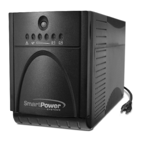
Smart power
Smart power SBP-TBF Series User manual
Smart power
Smart power Venus Series User manual
Smart power
Smart power Smart Sine Pro Series User manual
Smart power
Smart power DSS1500RT-TBF User manual
Smart power
Smart power SPV0400U-TBF User manual
Smart power
Smart power SBP1000TBF User manual
Smart power
Smart power SBP0400TBF-6U User manual


