Smart watch H20SWDVR4R User manual

SmartWatch Digital Video Recorder
H20SWDVR4R / H20SWDVR8 / H20SWDVR16
H20SWDVR16R / H20SWDVR32R
Quick Guide

SmartWatch DVR Operation Manual
1
The information in this quick guide is subject to change without notice. SmartWatch®
assumes no responsibility for any errors or omissions in this quick guide.
Regulatory information
FCC information
FCC compliance: This equipment has been tested and found to comply with the limits for a digital device,
pursuant to part 15 of the FCC Rules. These limits are designed to provide reasonable protection against
harmful interference when the equipment is operated in a commercial environment. This equipment generates,
uses, and can radiate radio frequency energy and, if not installed and used in accordance with the instruction
manual, may cause harmful interference to radio communications. Operation of this equipment in a residential
area is likely to cause harmful interference in which case the user will be required to correct the interference at
his own expense.
FCC conditions
This device complies with part 15 of the FCC Rules. Operation is subject to the following two conditions:
1. This device may not cause harmful interference.
2. This device must accept any interference received, including interference that may cause undesired
operation.
EU Conformity Statement
This product and - if applicable - the supplied accessories too are marked with "CE" and
comply therefore with the applicable harmonized European standards listed under the Low
Voltage Directive 2006/95/EC, the EMC Directive 2004/108/EC, the RoHS Directive
2011/65/EU.
2012/19/EU (WEEE directive): Products marked with this symbol cannot be disposed of as unsorted
municipal waste in the European Union. For proper recycling, return this product to your local supplier upon
the purchase of equivalent new equipment, or dispose of it at designated collection points. For more
information see: www.recyclethis.info.
2006/66/EC (battery directive): This product contains a battery that cannot be disposed of as unsorted
municipal waste in the European Union. See the product documentation for specific battery information. The
battery is marked with this symbol, which may include lettering to indicate cadmium (Cd), lead (Pb), or
mercury (Hg). For proper recycling, return the battery to your supplier or to a designated collection point. For
more information see: www.recyclethis.info.

SmartWatch DVR Operation Manual
2
Preventive and Cautionary Tips
Before connecting and operating your device, please be advised of the following tips:
•Ensure unit is installed in a well-ventilated, dust-free environment.
•Unit is designed for indoor use only.
•Keep all liquids away from the device.
•Ensure environmental conditions meet factory specifications.
•Ensure unit is properly secured to a rack or shelf. Major shocks or jolts to the unit as a result of dropping it
may cause damage to the sensitive electronics within the unit.
•Use the device in conjunction with a UPS if possible.
•Power down the unit before connecting and disconnecting accessories and peripherals.
•A factory recommended HDD should be used for this device.
•Improper use or replacement of the battery may result in explosion. Replace with the same or equivalent
type only. Dispose of used batteries according to the instructions provided by the battery manufacturer.
Default User Name: admin
Default Password: 12345

SmartWatch DVR Operation Manual
3
1. Front Panels
The front panel of the H20SWDVR4R, H20SWDVR8 & H20SWDVR16 are shown in Figure 1.1:
Figure 1.1 Front panel of H20SWDVR4R, H20SWDVR8 & H20SWDVR16
Table 1.1 Description of H20SWDVR4R, H20SWDVR8 & H20SWDVR16 Front Panel Features
No.
Name
Function Description
1
POWER
POWER indicator turns green when DVR is powered up.
2
STATUS
STATUS indicator lights in red when HDD is reading/writing.
3
Tx/Rx
Tx/Rx indictor blinks green when network connection is functioning
properly.
4
IR Receiver
Receiver for IR remote.
5
USB Interface
Connects USB mouse or USB flash memory devices.
The front panel of the H20SWDVR16R & H20SWDVR32R is shown below:
Figure 1.2 Front panel of H20SWDVR16R & H20SWDVR32R
Table 1.2 Description of H20SWDVR16R & H20SWDVR32R Front Panel Features
No.
Name
Function Description
1
POWER
ON/OFF
Power on/off switch.
2
IR Receiver
Receiver for IR remote control.
3
USB
Connect to USB mouse or USB flash memory devices.
4
DVD-ROM
Slot for DVD-ROM.
5
POWER
Power indicator lights in green when DVR is powered up.
READY
Ready indicator is normally green, indicating that the DVR is functioning
properly.
STATUS
Indicator turns green when DVR is controlled by an IR remote control with an
address within 1~254;
Indicator turns red when the SHIFT button is used;
Indicator does not light when the DVR is controlled by a keyboard or by the
IR remote control with an address of 255;
Indicator turns green when the DVR is controlled by an IR remote control
(with an address within 1~254) and keyboard at the same time , and the
SHIFT button is not used;
Indicator turns orange : (a) when the DVR is controlled by an IR remote

SmartWatch DVR Operation Manual
4
control (with an address within 1~254) and keyboard at the same time and the
SHIFT button is used as well; (b) when the DVR is controlled by an IR
remote control (with an address within 1~254) and the SHIFT button is used.
ALARM
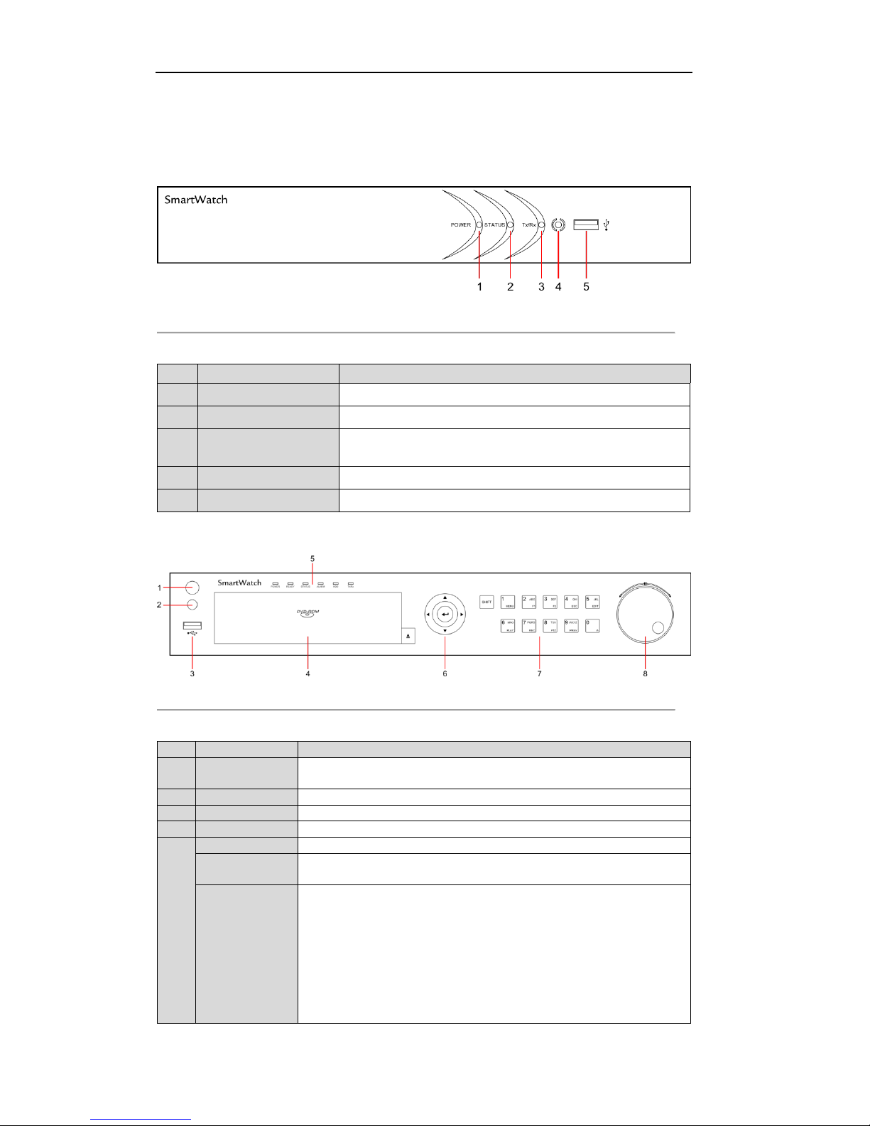
Alarm indicator turns red when a sensor alarm is detected.
HDD
HDD indicator blinks in red when data is being read from or written to HDD.
Tx/Rx
Tx/Rx indicator blinks in green when network connection is functioning
properly.
SHIFT
Switch of compound keys between the numeric/letter input and functional
control.
6
1/MENU
Enter numeral “1”;
Access the main menu interface.
2/ABC/F1
Enter numeral “2”;
Enter letters “ABC”;
The F1 button can be used to select all items on a list;
In PTZ Control mode, the F1 button can be used to zoom out on a PTZ
camera;
In live view or playback mode, the F1 button can be used to switch between
main and spot video output.
3/DEF/F2
Enter numeral “3”;
Enter letters “DEF”;
In PTZ Control mode, the F1 button can be used to zoom in on a PTZ camera;
The F2 button can be used to cycle through tab pages.
4/GHI/ESC
Enter numeral “4”;
Enter letters “GHI”;
Exit and return to the previous menu.
5/JKL/EDIT
Enter numeral “5”;
Enter letters “JKL”;
Delete characters before cursor;
Select a checkbox and ON/OFF switch;
Start/stop record clipping in playback.
6/MNO/PLAY
Enter numeral “6”;
Enter letters “MNO”;
In Playback mode, get direct access to playback interface.
7/PQRS/REC
Enter numeral “7”;
Enter letters “PQRS”;
Manual record, for direct access to manual record interface; manually
enable/disable record.
8/TUV/PTZ
Enter numeral “8”;
Enter letters “TUV”;
Access PTZ control interface.
9/WXYZ/PREV
Enter numeral “9”;
Enter letters “WXYZ”;
Multi-camera display in live view;
In Playback mode or MenuPlaybackTag playback interface, this button
can be used to delete the selected tag.
0/A
Enter numeral “0”;
Switch between input methods (upper and lowercase alphabet, symbols and
numeric input).
In Playback mode, this button can be used to add a default tag.
7
DIRECTION
The DIRECTION buttons are used to navigate between different fields and
items in menus.
In Playback mode, the Up and Down buttons are used to speed up and slow
down recorded video.
In All-day Playback mode, the Left and Right buttons can be used to select
the recorded video of the next/previous day; in Playback by Normal Video
Search, the Left and Right buttons can be used to select the next/previous
recorded file.
In Live View mode, the directional buttons can be used to cycle through
channels.

SmartWatch DVR Operation Manual
5
In PTZ control mode, the buttons can control the movement of the PTZ
camera.
ENTER
Confirm selection in any of the menu modes. It can also be used to tick
checkbox fields.
In Playback mode, it can be used to play or pause the video.
In Single-frame Playback mode, pressing the ENTER button will advance the
video by a single frame.
In Auto-switch mode, it can be used to stop /start auto switch.
8
JOG SHUTTLE
Control
Move the active selection in a menu. The inner ring will move the selection
up and down; the outer ring will move it left and right.
In Playback mode, the inner ring is used to jump 30s forward/backward in
video files. The outer ring can be used to speed up/slow down the video.
In Live View mode, it can be used to cycle through different channels.
In PTZ control mode, in can control the movement of the PTZ camera.
2. Rear Panels
The rear panels of the H20SWDVR4R, H20SWDVR8, H20SWDVR16 DVRs are shown in
Figure 2.1, Figure 2.2 & Figure 2.3.
Figure 2.1 Rear Panel of H20SWDVR4R
Figure 2.2 Rear Panel of H20SWDVR8
Figure 2.3 Rear Panel of H20SWDVR16

SmartWatch DVR Operation Manual
6
Table 2.1 Description of H20SWDVR4R, H20SWDVR8 & H20SWDVR16 Rear Panel
No.
Item
Description
1
VIDEO IN
BNC connector for analog video input.
2
VIDEO OUT
BNC connector for video output.
3
USB Interface
Connects USB mouse or USB flash memory devices.
4
HDMI
HDMI video output.
5
Alarm In/Out
Connector for alarm input/output.
6
VGA
DB15 connector for VGA output. Display local video output and menu.
7
AUDIO IN
RCA connector for audio input.
8
AUDIO OUT
RCA connector for audio output.
9
LAN Interface
Connector for LAN (Local Area Network).
10
RS-485 Interface
Connector for RS-485 devices. Connect the D+ and D- terminals to T+
and T- of PTZ receiver respectively.
11
12V
12VDC power supply.
12
POWER
Switch for turning on/off the device.
13
GND
Ground (needs to be connected when DVR starts up).
The rear panel of the H20SWDVR16R is shown in Figure 2.4
Figure 2.4 Rear Panel of H20SWDVR16R
Table 2.2 Description of H20SWDVR16R Rear Panel
No.
Item
Description
1
VIDEO IN
BNC connector for analog video input.
2
RS-232
Connector for RS-232 devices.
3
VGA
DB15 connector for VGAoutput. Display local video output and menu.
4
MAIN VIDEO OUT
BNC connector for video output.
SPOT VIDEO OUT
BNC connector for spot video output.
5
HDMI
HDMI video output.
6
AUDIO IN
RCA connector for audio input.
7
USB Interface
Connects USB mouse or USB flash memory devices.
8
AUDIO OUT
RCA connector for audio output.
9
LAN Interface
RJ45 10M / 100M / 1000M Ethernet interface.
10
RS-485 Interface
Connector for RS-485 devices. Connect the D+ and D- terminals to R+ and
R- terminals of PTZ receiver respectively.
11
Alarm In/Out
Connector for alarm input/output.
12
Loop Out
Connector for video loop output interface.

SmartWatch DVR Operation Manual
7
13
eSATA
Connects external SATA HDD, DVD-R/W.
14
GND
Ground (needs to be connected when DVR starts up)
15
110~240VAC
Power supply.
16
POWER
Switch for turning on/off the device.
The rear panel of the H20SWDVR32R is shown in Figure 2.5
Figure 2.5 Rear Panel of H20SWDVR32R
Table 2.3 Description of H20SWDVR32R Rear Panel
No.
Item
Description
1
VIDEO OUT
BNC connectors for video output.
2
AUDIO OUT
RCA connector for audio output.
3
LINE IN
RCA connector for audio input.
4
AUDIO IN
RCA connector for audio input.
5
VIDEO IN
BNC connector for analog video input.
6
VGA
DB15 connector for VGAoutput. Display local video output and menu.
7
HDMI
HDMI video output.
8
USB Interface
Connects USB mouse or USB flash memory devices.
9
LAN Interface
RJ45 10M / 100M / 1000M Ethernet interface.
10
RS-232
Connector for RS-232 devices.
11
RS-485 Interface
Connector for RS-485 devices. Connect the D+ and D- terminals to R+ and
R- terminals of PTZ receiver respectively.
12
Alarm In/Out
Connector for alarm input/output.
13
eSATA
Connects external SATA HDD, DVD-R/W.
14
GND
Ground (needs to be connected when DVR starts up)
15
110~240VAC
Power supply.
16
POWER
Switch for turning on/off the device.

SmartWatch DVR Operation Manual
8
3. Starting Up and Shutting Down the Device
Purpose:
Proper startup and shutdown procedures are crucial to extending the life of the device.
Before you start:
Check that the voltage of the power supply matches the device’s requirement, and the ground connection is
working properly.
Starting up the device:
Steps:
1. Check the power supply is plugged into an electrical outlet. It is HIGHLY recommended that an
Uninterruptible Power Supply (UPS) be used in conjunction with the device.
2. Press the POWER button on the rear panel. The Power indicator LED should turn green indicating that
the unit begins to start up.
Shutting down the device:
Steps:
1. Enter the Shutdown menu.
Menu > Shutdown
Figure 3.1 Shutdown Menu
2. Click the Shutdown button to enter the following dialog box:
Figure 3.2 Dialog Box for Shutdown
3. Click the Yes button.
4. Turn off the power switch on the rear panel of DVR.
Rebooting the device
In the Shutdown menu (Figure 3.1), you can also click Reboot to reboot the device.

SmartWatch DVR Operation Manual
9
4. Menu Structure
5. Network Settings
Default Network Values:
IPv4 Address
192.168.1.250
IPv4 Subnet Mask
255.255.255.0
IPv4 Default Gateway
192.168.1.254
Server Port
8000
HTTP Port
88
RTSP Port
554
To view the DVR via a web browser on a local network, enter the following address
in the browser address bar: http://192.168.1.250:88
5.1 General Network Settings
Purpose:
Network settings must be properly configured before you can operate the device over a network.
Steps:
1. Enter the Network Settings interface.
Menu > Configuration > Network

SmartWatch DVR Operation Manual
10
Figure 5.1.1 General Network Settings of H20SWDVR4R, H20SWDVR16 & H20SWDVR32
Figure 5.1.2 General Network Settings of H20SWDVR16R & H20SWDVR32R
2. Select the General tab.
3. In the General Settings interface:
You can configure the following settings: NIC Type, IPv4 Address, IPv4 Gateway, MTU and DNS
Server.
The H20SWDVR4R, H20SWDVR8 & H20SWDVR16 models provide one 10M/100Mbps self-
adaptive network interface, and the H20SWDVR16R & H20SWDVR32R models provide one
10M/100M/1000Mbps self-adaptive network interface.
If the DHCP server is available, you can click the checkbox of DHCP to automatically obtain an IP
address and other network settings from that server.
The valid value range of MTU is 500 ~ 1500.
4. After having configured the general settings, click the Apply button to save the settings.
5.2 Configuring RTSP
Purpose:
The RTSP (Real Time Streaming Protocol) is a network control protocol designed for use in entertainment and

SmartWatch DVR Operation Manual
11
communications systems to control streaming media servers.
Steps:
1. Enter the Network Settings menu by clicking Menu > Configuration > Network.
2. Select the More Settings tab to enter the More Settings menu.
Figure 5.2.1 RTSP Settings Interface
3. Enter the RTSP port in the text field of RTSP Service Port. The default RTSP port is 554, and you
can change it according to different requirements.
4. Click the Apply button to save and exit the menu.
5.3 Configuring Server and HTTP Ports
Purpose:
You can change the server and HTTP ports in the Network Settings menu. The default server port is 8000 and
the default HTTP port is 80.
Steps:
1. Enter the Network Settings interface.
Menu > Configuration > Network
2. Select the More Settings tab to enter the More Settings interface.
3. Enter new Server Port and HTTP Port.
Figure 5.3.1 Host/Others Settings Menu
4. Enter the Server Port and HTTP Port in the text fields. The default Server Port is 8000 and the HTTP
Port is 80, and you can change them according to different requirements.
5. Click the Apply button to save and exit the interface.
The Server Port should be set to the range of 2000-65535 and it is used for remote client software access.
The HTTP port is used for remote IE access.
Other manuals for H20SWDVR4R
1
This manual suits for next models
4
Table of contents
Other Smart watch DVR manuals

Smart watch
Smart watch SWE4 Series Operator's manual

Smart watch
Smart watch H20HVR4A4I User manual

Smart watch
Smart watch Eco Compact User manual

Smart watch
Smart watch H20HVR4A4I User manual

Smart watch
Smart watch Eco Instruction manual

Smart watch
Smart watch H20SWDVR4R User manual

Smart watch
Smart watch Eco User manual