Smart watch Eco User manual

Digital Video Recorders
SmartWatch® Eco/Eco Compact
Installation Manual
SmartWatch® Eco Compact
SmartWatch® Eco

2
This symbol is intended to
alert the user to the presence
of unprotected “Dangerous
voltage within the product's
enclosure that may be strong
enough to cause a risk of
electric shock.
This symbol is intended to
alert the user to the presence
of important operating and
mainte nanc e (se rvic ing )
instructions in the literature
accompanying the appliance.
WARNING
TO REDUCE THE RISK OF FIRE OR
ELECTRIC SHOCK, DO NOT EXPOSE
THIS APPLIANCE TO RAIN OR
MOISTURE.
NOTE: This equipment has been tested
and found to comply with the limits for a
class digital device, pursuant to part 15 of
the FCC Rules. These limits are designed
to provide reasonable protection against
harmful interference when the equipment is
operated in a commercial environment.
This equipment generates, uses, and can
radiate radio frequency energy and, if not
installed and used in accordance with the
instruction manual, may cause harmful
interference to radio communications.
Operation of this equipment in a residential
area is likely to cause harmful interference
in which case the user will be required to
correct the interference at his own
expense.
Disposal of Old Electrical & Electronic Equipment (Applicable in t e
European Union and ot er European countries wit separate collection
T is symbol on t e product or on its packaging indicates t at t is product s all not
be treated as ouse old waste. Instead it s all be anded over to t e applicable
collection point for t e recycling of electrical and electronic equipment. By
ensuring t is product is disposed of correctly, you will elp prevent potential
negative consequences for t e environment and uman ealt , w ic could
ot erwise be caused by inappropriate waste andling of t is product. T e recycling
of materials will elp to conserve natural resources. For more detailed information
about recycling of t is product, please contact your local city office, your
ouse old waste disposal service or t e s op w ere you purc ased t e product.

3
Index
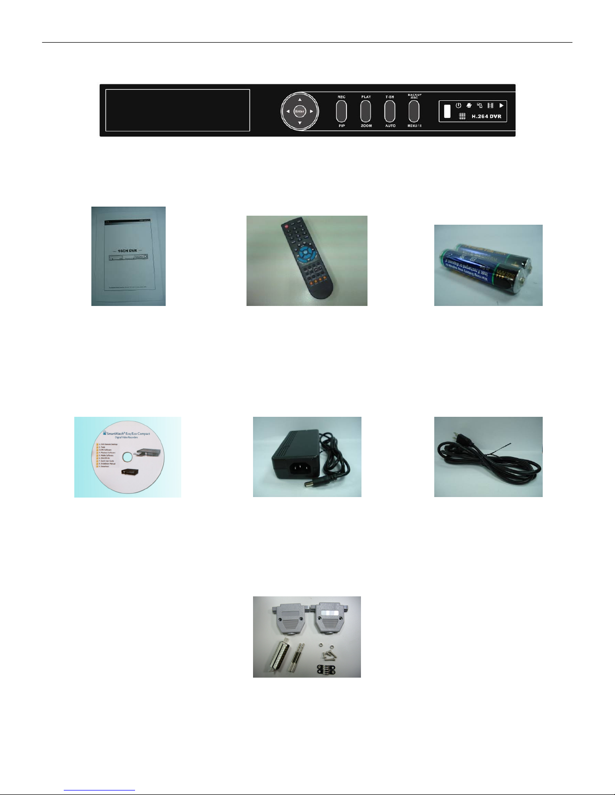
Box Contents.................................................................................................................................................................4
Front Panel Controls ...................................................................................................................................................5-6
SmartWatch Eco Compact..................................................................................................................................5
SmartWatch Eco................................................................................................................................................6
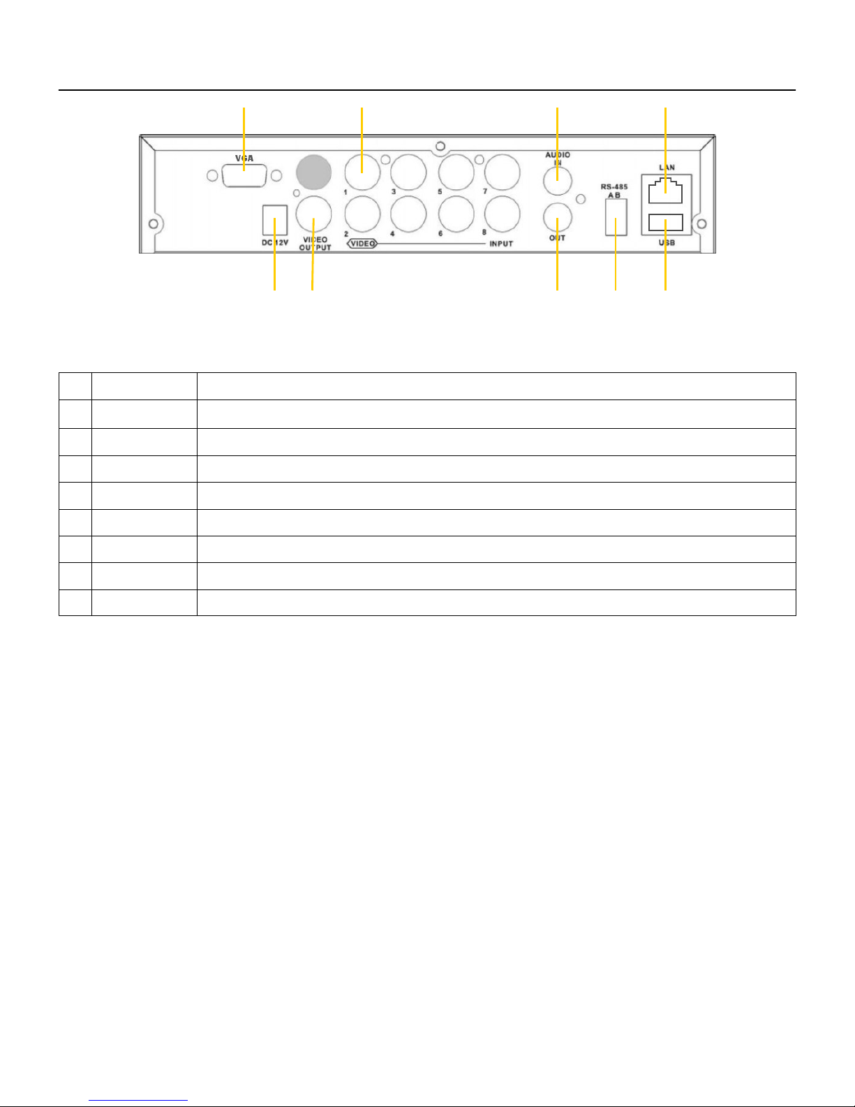
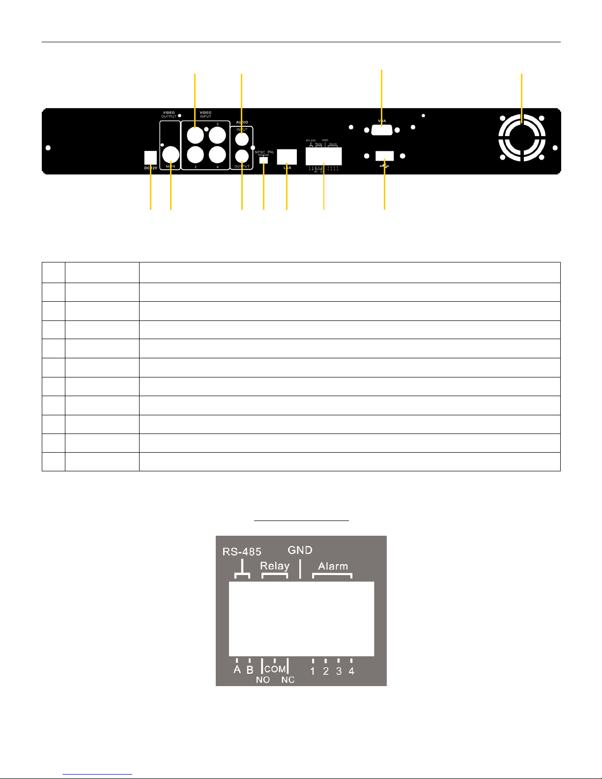
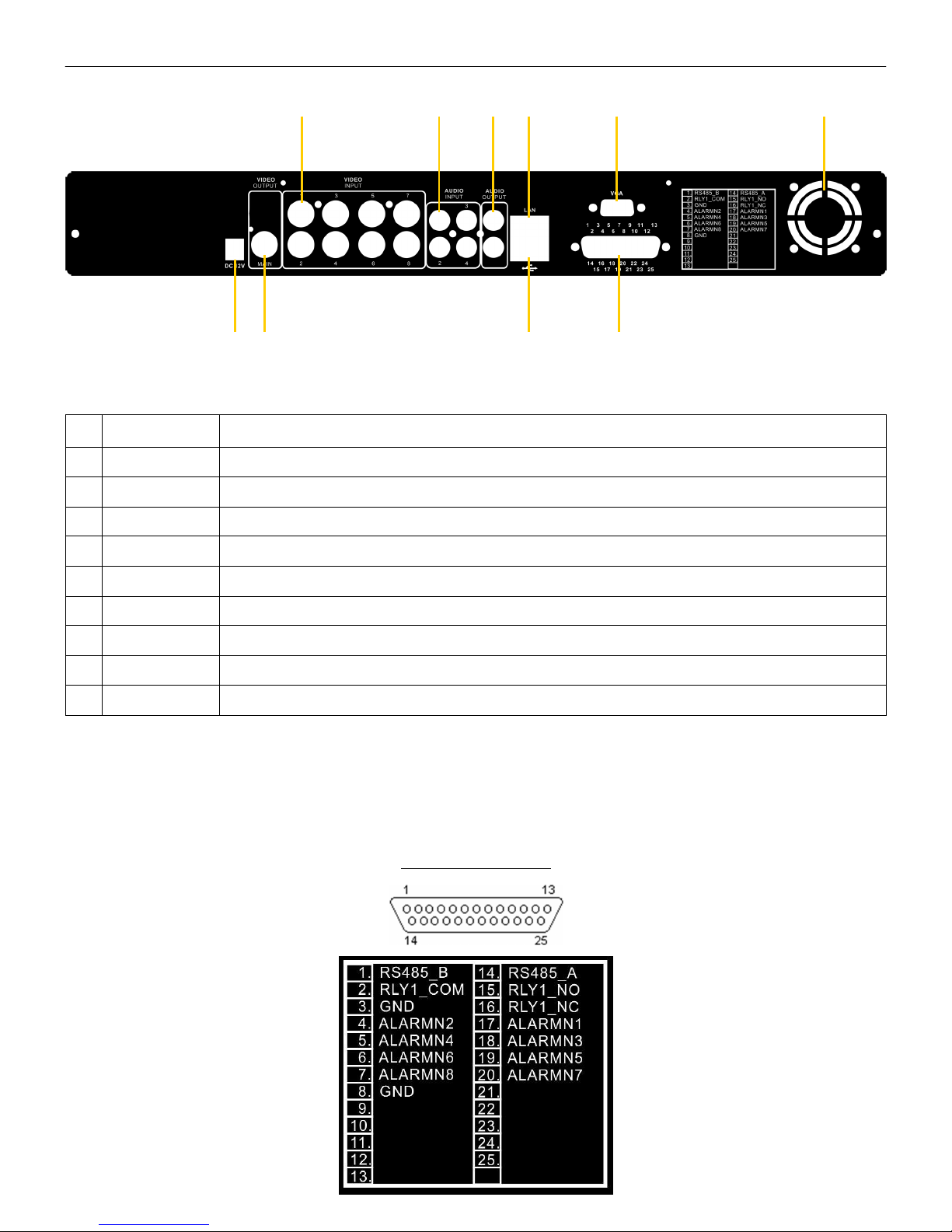
Rear Panel Connections..........................................................................................................................................7 - 11
SmartWatch Eco Compact (4 channel) ................................................................................................................7
SmartWatch Eco Compact (8 channel) ................................................................................................................8
SmartWatch Eco (4 channel) ..............................................................................................................................9
SmartWatch Eco (8 channel) ............................................................................................................................10
SmartWatch Eco (16 channel) ..........................................................................................................................11
Remote Control Functions In Live Mode ........................................................................................................................12
Mouse Functions In Live Mode......................................................................................................................................13
On-Screen Graphical Icons In Live Mode.......................................................................................................................14
On-Screen Graphical Icons In Live Mode When Connected Through ‘DVR Remote Desktop’ ...............................14
Playback Mode ............................................................................................................................................................15
Remote Control Functions In Playback Mode.....................................................................................................15
Mouse Functions In Playback Mode ..................................................................................................................15
PTZ Control.................................................................................................................................................................16
Remote Control Functions In PTZ Mode ............................................................................................................16
Mouse Functions in PTZ Mode..........................................................................................................................16
Main Menu Setup....................................................................................................................................................17-33
Record Setup...................................................................................................................................................18
Event Setup.....................................................................................................................................................19
Schedule Setup ...............................................................................................................................................21
Camera Setup .................................................................................................................................................22
Account Setup .................................................................................................................................................22
Networking Setup.............................................................................................................................................24
PTZ & RS485 Setup.........................................................................................................................................28
System Setup ..................................................................................................................................................29
Utility Setup .....................................................................................................................................................33
Diagnostic .......................................................................................................................................................33
Backup Mode...............................................................................................................................................................34
Search Mode ..........................................................................................................................................................35-36
Event Search...................................................................................................................................................35
Time Search ....................................................................................................................................................36
File Search ......................................................................................................................................................36
Remote Software Installation and Setup .................................................................................................................37 - 39
Software Installation.........................................................................................................................................37
How to Remotely Monitor, Playback, Backup and Configure via Internet Explorer.................................................38
System Requirements for DVR remote desktop .................................................................................................39
Specifications ..............................................................................................................................................................40
CMS Installation And Usage Guide ........................................................................................................................41 - 53
CMS Installation...............................................................................................................................................41
CMS Software .................................................................................................................................................42
DVRs, Groups & Events ...................................................................................................................................43
Local PC Information and Control......................................................................................................................44
Main Display ....................................................................................................................................................44
Operation Bar ..................................................................................................................................................47
Appendix 1: I-DVR.net Registration ........................................................................................................................54 - 55
Appendix 2: Remote Monitoring IE ActiveX Control Installation Instruction ................................................................56 - 59

4
Box Contents
2. Quick Reference Guide 3. IR Remote Control 4. Batteries x 2
5. CD 6. Power Adaptor 7. Power Cord
8. 25 Way Connector
(8 / 16 channel models only)
1. DVR

5
SmartWatch Eco Compact - Front Panel Controls
1 Power LED Power status
2 LAN LED Connected to the internet (green). Remote user logged in (red).
3 Play LED DVR is in playback mode
4 Record LED DVR is recording
5 IR Sensor Input sensor for the remote control
6 USB Port USB port
1 2 3 4 5 6

6
SmartWatch Eco - Front Panel Controls
1 DVD Writer DVD-RW backup device
2 ▼ / ■ In Setup mode, press to move cursor down. In Playback mode, press to stop.
▲ / SLOW In Setup mode, press to move cursor up. In Playback mode, press to slow down.
► / ►► In Setup mode, press to move cursor right. In Playback mode, press to fast forward.
◄ / ◄◄ In Setup mode, press to move cursor left. In Playback mode, press to rewind.
3 REC Start or stop recording (depending on schedule setup).
4 PLAY Start playback (from start of current hour).
5 T-SH Enter search menu.
6 BACKUP / ESC In Live mode, press to display the Backup menu. In Setup mode, press to return to previous page.
7 USB Port USB port
LED Display : Power status.
: Hard Drive status.
: Connected to the internet (green). Remote user logged in (red).
: DVR is recording.
: DVR is in playback mode.
9 ENTER In Setup mode, press to enter values. In Playback mode, press to switch between full screen quad, 9-
channel & 16-channel displays.
10 PIP In Live mode, press to display picture in picture.
11 ZOOM In Live or Playback modes, press to zoom in digitally on images.
12 AUTO Auto sequence display
13 MENU / II In Live mode, press to display menu. In Playback mode, press to pause playback.
14 IR Sensor Input sensor for the remote control.
1 2 3 4 5 6 7
9 10 11 12 13 14

7
SmartWatch Eco Compact (4 channel) - Rear Panel
Connections
1 DC 12V DC 12V input
2 VIDEO out Main/Spot monitor output (BNC)
3 VIDEO in Camera inputs
4 AUDIO in Audio input
5 AUDIO out Audio output
6 VGA Main monitor output (VGA)
7 USB USB port for connecting mouse
RS-485 RS-485 port for PTZ control
9 LAN Ethernet port
1 2 5 6 7 9
3 4

8
SmartWatch Eco Compact ( channel) - Rear Panel
Connections
1 VGA Main monitor output (VGA)
2 DC 12V DC 12V input
3 VIDEO out Main/Spot monitor output (BNC)
4 VIDEO in Camera inputs
5 AUDIO in Audio input
6 AUDIO out Audio output
7 RS-485 RS-485 port for PTZ control
LAN Ethernet port
9 USB USB port for connecting mouse
2 3 6 7 9
1 4 5

9
SmartWatch Eco (4 Channel) - Rear Panel Connections
1 VIDEO in Camera inputs
2 AUDIO in Audio input
3 VGA Main monitor output (VGA)
4 Fan Fan
5 DC 12V DC 12V input
6 Video output Main/Spot monitor output (BNC)
7 AUDIO out Audio output
NTSC/PAL Switch between NTSC and PAL format (make sure the switch is in the PAL position)
9 LAN Ethernet port
10 External I/O External I/O port (see below for pin layout)
11 USB USB port for mouse connection
5 6 7 9 10 11
1 2 3 4
External I/O Pin Layout
SPOT

10
SmartWatch Eco ( Channel) - Rear Panel Connections
1 VIDEO in Camera inputs
2 AUDIO in Audio inputs
3 AUDIO out Audio outputs
4 LAN Ethernet port
5 VGA Main monitor output (VGA)
6 Fan Fan
7 DC 12V DC 12V input
Video output Main/Spot monitor output (BNC)
9 USB USB port for mouse connection
10 External I/O External I/O port (see below for pin layout)
7 9 10
1 2 3 4 5 6
External I/O Pin Layout
SPOT

11
SmartWatch Eco (16 Channel) - Rear Panel Connections
1 Video output Main/Spot monitor output (BNC)
2 VIDEO in Camera inputs
3 AUDIO in Audio inputs
4 External I/O External I/O port (see below for pin layout)
5 Fan Fan
6 NTSC/PAL Switch between NTSC and PAL format (make sure the switch is in the PAL position)
7 AUDIO out Audio output
USB USB port for mouse connection
9 LAN Ethernet port
10 ON/OFF Power switch
11 DC 12V DC 12V input
12 e-SATA External SATA hard disks port for external storage
13 VGA Main monitor output (VGA)
6 7 9 10 11 12 13
1 2 3 4 5
External I/O Pin Layout
SPOT

12
Remote Control Functions In Live Mode
Button Description
REC Start or stop recording (depending on schedule setup).
PLAY Start playback (from start of current hour).
LOCK Lock DVR controls (password required).
1,2,3,4... Select channel.
FREEZE Freeze picture.
Displays quad division.
Displays 9-channel division (N/A on 4-channel DVR).
Displays 13-channel division (N/A on 4-channel or 8-channel DVR).
Displays 16-channel division (N/A on 4-channel or 8-channel DVR).
ENTER/MODE Toggle between cameras and quad mode.
MENU / II Enter setup menu.
BK-UP/ESC Enter backup menu.
SRH Enter search menu.
MUTE Mute live audio.
STATUS Display DVR status.
OSD Toggle the on-screen display.
ZOOM/ZOOM - Digital zoom.
PIP/ZOOM + Enter ‘picture in picture’ mode.
PTZ Enter PTZ mode (when PTZ cameras are connected).
AUTO Run camera sequence on main monitor.
DVR 1 / 2 / 3 / 4 Selects DVR to control when used on sites with multiple DVRs.
Press DVR1 on t e remote control to enable it

13
Mouse Functions In Live Mode
Description
Resting the cursor on this icon will bring up the following four menu icons.
Enter setup menu.
Enter search menu.
Enter backup menu.
Enter PTZ mode (when PTZ cameras are connected).
Start or stop recording (depending on schedule setup).
Start playback (from start of current hour).
Resting the cursor on this icon will bring up the following five display icons.
Freeze picture
Enter ‘picture in picture’ mode.
Digital zoom
Run camera sequence on main monitor.
Lock DVR controls (password required).
Full screen display.
Quad display.
9-channel display.
13-channel display.
16-channel display.
Icon
Rig t-clicking t e mouse anyw ere on t e screen will bring up t e following icons

14
On-Screen Graphical Icons In Live Mode
Icon Description
DVR is recording.
1~4 Live audio is on.
Live audio is off.
Motion is detected.
Sensor is triggered.
Video loss detected.
USB device detected.
DVD burner is detected.
Connected to the LAN cable.
Film: Normal recording.
Clock: Schedule recording.
Auto sequence is on.
2X - 8X Digital zoom level.
Live screen is paused.
DVR is locked.
PTZ.
HDD status (99% used).
Current time display (can be repositioned)
On-Screen Graphical Icons In Live Mode When
Connected Through ‘DVR Remote Desktop’
Icon Description
/ Transmit at high / low quality.
/ Full screen / half screen display.
Record locally.
Take snap shot.
Set up path for saving recordings and snapshots.
Enable / disable shortcut toolbar.

15
Playback Mode
Button Description
ENTER/MODE Switch between full screen, quad, 9-channel and 16-channel displays
MENU / II Pause playback
PLAY Play back at normal speed
▲ / SLOW Slows playback by 1/2, 1/4, 1/8 or 1/16
◄ / ◄◄ Rewind playback at 2X, 4X 8X, 16X, 32X and 64X speeds
► / ►► Fast forward playback at 2X, 4X 8X, 16X, 32X and 64X speeds
▼ / ■ Stop playback
Mouse Functions In Playback Mode
Icon Description
Rewind
Fast forward
/ Play / pause
Slow playback
Stop playback
Playback frame by frame
Full screen display
Quad display
Digital zoom in playback
To display a single camera on the full screen in playback mode, double left click it on the multi-camera display. To revert
back to the multi-camera display, double left click again.
To enter playback mode:
• Press PLAY on the front panel
• Press PLAY on the remote control
• Click when using the mouse
Remote Control Functions In Playback Mode

16
PTZ Control
Mouse Functions In PTZ Mode
To enter PTZ mode:
• Press PTZ on the remote control
• Click when using the mouse
When the PTZ icon is displayed in the upper left corner of the screen, the
function icons will be displayed in the lower right corner of the screen. These can be
dragged around the screen using the mouse.
Remote Control Functions In PTZ Mode
Button Description
▲ / SLOW Move PTZ up.
▼ / ■ Move PTZ down.
◄ / ◄◄ Move PTZ to the left.
► / ►► Move PTZ to the right.
ZOOM + PTZ zoom-in.
ZOOM - PTZ zoom-out.
FOCUS + PTZ focus-in.
FOCUS - PTZ focus-out.
IRIS + PTZ iris-open.
IRIS - PTZ iris-close.
TOUR Activate PTZ preset tour (when preset is programmed).
PRESET
To save a preset location, move the camera to the desired scene, press PRESET and a number key.
This will save this scene as the preset number selected e.g. to save a scene as Preset 1, press
‘PRESET’ and ‘1’.
PLAY + NUMBER To call a preset, press Play and the number of the desired preset.
Icon Description
Exit PTZ Mode and return to Live Mode.
Preset number N (1~64).
Go to preset number N.
Set current PTZ location at preset number N.
Move PTZ in 360°
PTZ zoom in; PTZ zoom out
PTZ focus in; PTZ focus out.
PTZ IRIS open; PTZ IRIS close.

17
Main Menu Setup
Item Description
Switch between capital and small letters.
/ Switch between numbers and letters.
Press to cancel the setup, and re-choose the login account.
Delete the last character.
Press to enter the password. If the password is correct, the required menu will open.
Space key.
Virtual Keyboard
To enter the DVR menus, a user name and password are required. The default password for the ‘Admin’ is ‘123456’.
Item Description
◄► Switch to different options under one item.
▲▼ Switch to different items.
MENU Save settings and return to LIVE mode.
ESC Back to upper level of menu without saving.
ENTER Enter the menu, or display virtual keyboard.
To navigate menus using remote control.

18
1. Record Setup
Item Description
HDD Full Stop - When the HDD is full the unit will stop recording.
Overwrite - The DVR will overwrite, when the HDD is full (default setting).
OSD position X X position for OSD.
OSD position Y Y position for OSD.
OSD position setup Set the position for time and date in playback.
Video Preservation Set up the video preservation period. Recorded video will be deleted automatically after the
selected preservation period (in hours).
Quality & Frame Rate Setup Set up the recording resolution, quality and frame rate per camera in normal and event
modes.
1.1. Quality & Frame Rate Setup
Note: 4c , 8c and 16c DVR will display differently.
Item Description
Normal setup / event setup Select mode to assign frame rate.
Resolution Select recording resolution: PAL:352X288,704X288,704X576.
No. Enable/disable selected channel.
Quality Select recording quality: Lowest/ Low/ Normal/ High/ Highest.
FPS Select recording frame rate.
Auto Automatically divides the maximum frame rate across cameras connected.

19
2. Event Setup
Item Description
Motion Setup Enter to set up motion detection.
Sensor Setup Enter to set up sensor detection.
2.1. Motion Setup
Item Description
Alarm Duration (Seconds) The alarm time in seconds when motion is detected (buzzer / relay).
Motion Popup Enable/Disable popup function all channels (across channels). When motion is detected in
LIVE mode, the detected channel image will pop up in full screen display.
Enable Check the box to Enable/Disable motion detection for each channel.
Sensitivity Set up Sensitivity value 1 to 10 for each channel. The lower value, the higher the sensitivity it
will be.
Motion Area Setup Enter to setup motion detection area.

20
2.1.1. Motion Area Setup
The screen is divided into 16x21 divisions: areas of detection are transparent, masked areas are in red. At default, all areas
are selected.
Item Description
Mask Mouse Selection Use mouse to select area.
All Area Detection Select the full screen.
Mask All Area Deselect all areas.
Continue Continue setup.
Exit & Save Save setup and exit.
Exit & Discard Cancel.
2.2. Sensor Setup
Item Description
Sensor Popup Check the box to Enable/Disable popup. When a Sensor is detected in LIVE mode, the detected
channel image will pop up in full screen.
All Off Disable all sensors.
All Low Set all sensor polarity low.
All High Set all sensor polarity high.
Sensor Polarity
Click or press ▼ to select between HIGH, LOW voltage for triggering sensor detection or OFF to turn
off polarity for each channel
Low Polarity: Sensor has not been triggered. When connected, sensor will be turned on.
Hig Polarity: Sensor has been triggered. When connected, sensor status will be turned off.
Off: Sensor is deactivated, and will not be turned on/off.
Note: 4CH DVR will display 4 c annels and 8CH DVR will display 8 c annels.
Other manuals for Eco
1
This manual suits for next models
1
Table of contents
Other Smart watch DVR manuals

Smart watch
Smart watch Eco Compact User manual

Smart watch
Smart watch H20HVR4A4I User manual

Smart watch
Smart watch H20SWDVR4R User manual

Smart watch
Smart watch H20SWDVR4R User manual

Smart watch
Smart watch Eco Instruction manual

Smart watch
Smart watch SWE4 Series Operator's manual

Smart watch
Smart watch H20HVR4A4I User manual