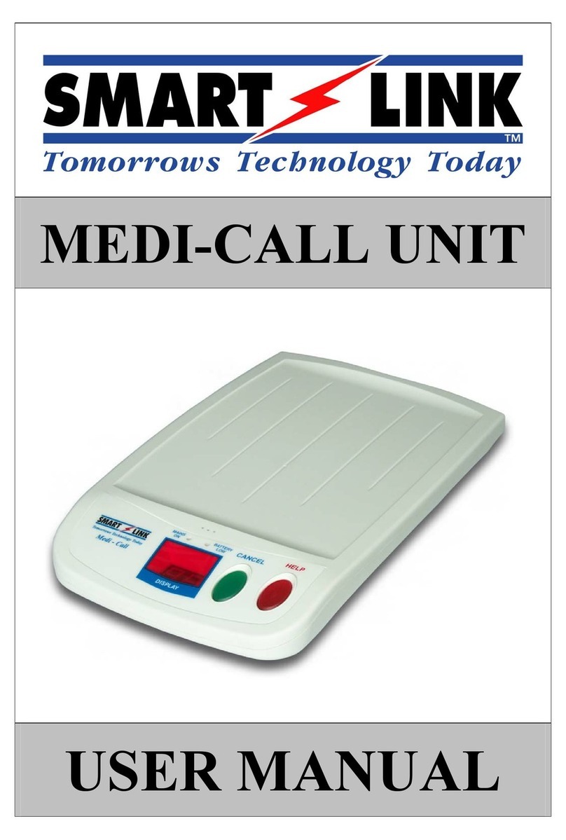
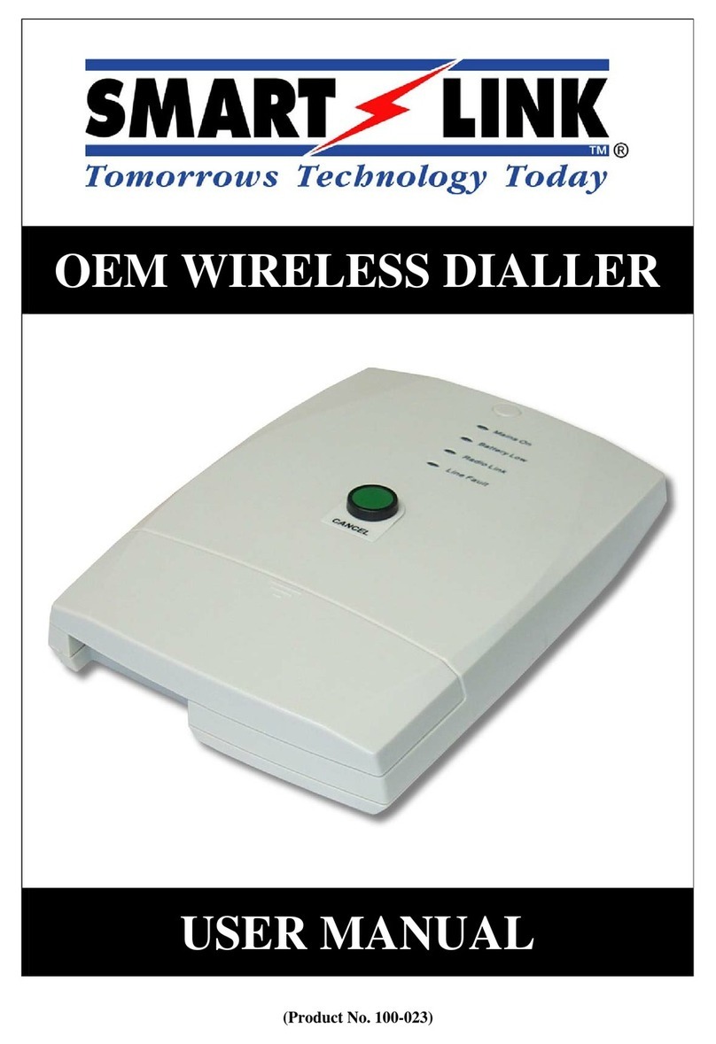
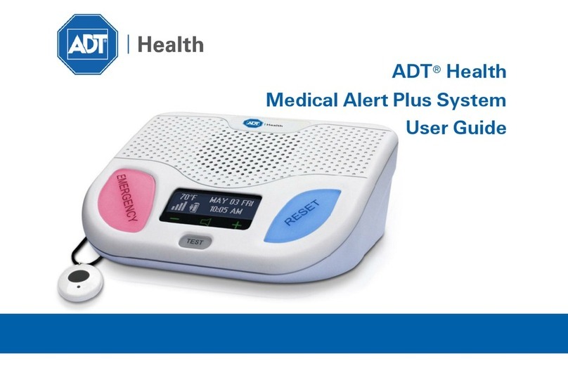
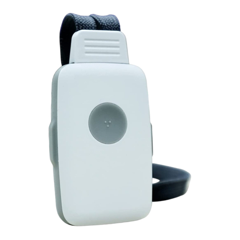
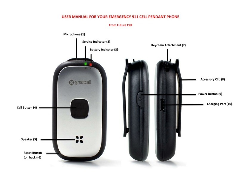
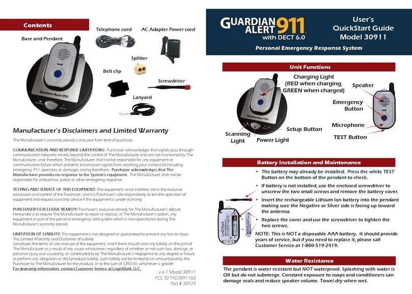
Smartlink MEDI-CALL UNIT User manual

MEDI-CALL UNIT
INSTALLATION MANUAL
Medi-Call V2.0 - V2.7 Installation Manual

Medi-Call V2.0 – V2.7 Installation Manual
1
© Copyright SmartLink International Pty Ltd
February 2006
475 Nepean Highway,
Brighton VIC 3186 Australia
Telephone: +61 3 9596 0770
Facsimile: +61 3 9596 8195
Web Site: www.smartlink.com.au
To the best of our knowledge, the information contained in this manual is correct at the time of print. SmartLink International Pty Ltd reserve
the right to make changes to the features and specifications at any time without prior notice in the course of product development.

Medi-Call V2.0 – V2.7 Installation Manual 2
1. TABLE OF CONTENTS
1. TABLE OF CONTENTS ..........................................................................................2
2. INTRODUCTION.....................................................................................................3
3. SMARTLINK FEATURES......................................................................................3
3. SMARTLINK FEATURES......................................................................................4
4. PROGRAM MODE...................................................................................................5
4.1 PRODUCT PROGRAMMING (DEFAULT =MEDI-CALL ADEMCO)........................................................................5
4.2 PROGRAMMING OPTIONS..................................................................................................................................5
4.3 PROGRAMMING RULES......................................................................................................................................5
5. PROGRAMMING OPTIONS..................................................................................6
5.1 PROGRAMMING MAIN MENU OPTIONS..........................................................................................................6
5.2 PROGRAMMING SUB MENU OPTIONS.............................................................................................................7
6. ALARMS..................................................................................................................23
6.1 DEVICE ALARMS................................................................................................................................................23
6.2 UNIT HELP BUTTON (U9) &INPUT ALARMS (DISPLAY I1-I4) .....................................................................24
6.3 MAINS FAIL (MAINS ON LIGHT FLASHING).........................................................................................................24
6.4 UNIT LOW BATTERY (BATTERY LOW LIGHT FLASHING) ..................................................................................24
6.5 SYSTEM ALARMS...............................................................................................................................................25
6.6 PRE-ALARM “PA”, ENTRY TIME “EN”AND EXIT TIME “EI”.........................................................................25
6.7 ALARM LOCKOUT “LC”.....................................................................................................................................25
6.8 INACTIVITY ALARM “IN”..................................................................................................................................25
6.9 TIME TILL FIRST TEST “1C” &TEST CALL TIME ‘2C” .................................................................................25
7. DIALLER.................................................................................................................26
7.1 REMOTE DTMF AUXILIARY OUTPUT CONTROL.........................................................................................26
7.2 PHONE NUMBERS “N1” TO “N4”........................................................................................................................27
7.3 ALARM REPORTING STATES...........................................................................................................................27
7.4 ALARMS REPORTED..........................................................................................................................................27
8. OPERATION MODE..............................................................................................28
8.1 NORMAL/DISARM MODE .................................................................................................................................28
8.2 ARM MODE..........................................................................................................................................................28
8.3 HOME MODE (NOTE:CONTACT ID VERSION ONLY) ...........................................................................................28
9. VOICE ANNUNCIATOR.......................................................................................29
9.1 “HANDS FREE” PHONE OPERATION...............................................................................................................29
9.2 AUTO ANSWER AND REMOTE VOICE CONTROL........................................................................................29
9.3 VOICE ONLY REPORTS “N3” AND “N4”.............................................................................................................30
9.4 BRITISH DTMF (UNIVERSAL MODE) VERSION ONLY................................................................................30
10.SPECIAL FUNCTIONS .........................................................................................30
10.1 OVER DUE TIMER (PILL TIMER)......................................................................................................................30
10.2 INACTIVITY MONITOR .....................................................................................................................................30
11.DIALLER REPORTING........................................................................................31
11.1 ADEMCO HIGH SPEED EXTENDED REPORTING..........................................................................................31
11.2 CONTACT ID REPORTING.................................................................................................................................32
11.3 BRITISH DTMF (UNIVERSAL )REPORTING...................................................................................................33
12.UP/DOWNLOAD REMOTE PROGRAMMING................................................34
13.USING SMARTLINK.............................................................................................35
13.1 NORMAL OPERATION.......................................................................................................................................35
13.2 TO CALL FOR HELP............................................................................................................................................35
14.DISPLAYS AND WARNINGS ..............................................................................36
15.SPECIFICATIONS.................................................................................................37
Medi-Call V2.0 – V2.7 Installation Manual
3
2. INTRODUCTION
Your SmartLink unit has been designed to provide you with the freedom and peace of mind in that, should you need
assistance or HELP, it is available to you 24 hours a day with the simple press of a Button.
The modern slim line design of the SmartLink unit allows it to be installed unobtrusively anywhere and is ready when you
need help. HELP can be summonsed by pressing a Button on your personal Pendant or Wristwatch, which you can wear
both inside your home or outside in the garden, ready for any emergency, giving you the freedom you enjoy for total
control at all times.
The SmartLink unit has been built to the highest of technical standards for the protection of people and property and
manufactured to Australian and International quality standards.
Your SmartLink unit can be supplied with additional fixed or portable Radio Key Pendants, which can be worn or placed
around the home as needed. Please contact your supplier for more information.
3. SMARTLINK FEATURES
RADIO KEY PENDANTS
Wristwatch, Neck Chain or
Fixed Waterproof Pendants
Dementia Proximity Key
(Blue Colour)
Button 1 = ARM or CALL
Button 2 = OFF or CANCEL
Button 3 = PANIC
Box Style Water Resistant
Pendant (Arthritis)
Wall Mounted
Call Points (Wireless)
Man-Down
Water Resistant Pendant
RADIO DETECTORS
Radio Smoke Detector
Radio PIR Detector
(Inactivity)
Radio Reed Switch
(Inactivity)

Medi-Call V2.0 – V2.7 Installation Manual 4
3. SMARTLINK FEATURES
TOP VIEW
BOTTOM VIEW

Medi-Call V2.0 – V2.7 Installation Manual
5
4. PROGRAM MODE
To enter one of the Programming Modes, the SmartLink unit must be turned Off by unplugging the Mains and the Battery
Switch must also be Off. There are two types of Programming Modes:
1. Product Programming - which programs SmartLink to a different Product Type.
2. Programming Options - which programs SmartLink Menu Options.
4.1 PRODUCT PROGRAMMING (Default = Medi-Call Ademco)
The Product Type is programmed by entering the Special Code on the SmartLink unit. This will reset all Programming
Options and will have to be completely reprogrammed again in the new mode. If the code is unknown then the SmartLink
unit will default to the previous Product Type and it’s Option Programming will be maintained. The SmartLink unit will
remain in this Mode for only 5 minutes if the code hasn’t been entered.
To enter Product Programming:
1. Hold down the CANCEL (Green) and HELP (Red) Buttons and Power up the SmartLink unit.
2. The SmartLink unit will beep once while “PP” will be displayed to indicate that it is in Product Programming.
3. Using the CANCEL (Green) and HELP (Red) Buttons, a Code may be entered as follows:
a. MEDI-CALL ADEMCO - Press CANCEL, CANCEL, CANCEL, HELP
b. MEDI-CALL BRITISH DTMF - Press CANCEL, CANCEL, HELP, HELP
c. MEDI-CALL CONTACT ID - Press CANCEL, HELP, HELP, HELP
4. Press the CANCEL (Green) and HELP (Red) Buttons at the same time to acknowledge end of Product
Programming. The SmartLink unit will beep twice while “u_” is displayed to indicate that it is now in Options
Programming.
4.2 PROGRAMMING OPTIONS
NOTE: If NO Buttons on the SmartLink unit or the Radio Key Pendants have been pressed within 5 minutes, the
SmartLink unit will revert back to NORMAL OPERATION MODE (NB: A Client Account Number and at least one
Phone Number must be programmed in for the SmartLink unit to Exit Program Mode and enter Normal Operation Mode).
To enter Options Programming:
1. Turn the Battery Switch to On and plug in the Mains.
2. The SmartLink unit will display the version number for 0.5 seconds and beep once.
3. “u_” is displayed to indicate that it is in Programming Options.
4.3 PROGRAMMING RULES
The easiest way to program the SmartLink unit is to use the large CANCEL (Green) Button and the HELP (Red)
Button on the SmartLink unit or using a programmed 3 Buttons Radio Key Pendant (ON, OFF & PANIC).
1
Press the CANCEL (Green) Button on the SmartLink unit to scroll through the Main
Menu Options or the Sub Menu Options.
2
Press the HELP (Red) Button on the SmartLink unit to view the programmed value for
that option. The values will be displayed flashing. To step through values, press the HELP
(Red) Button again.
3
To store an option selected, press the CANCEL (Green) and HELP (Red) Buttons at the
same time. The SmartLink unit will beep twice while flashing the display to acknowledge
that the option has been selected.

Medi-Call V2.0 – V2.7 Installation Manual 6
5. PROGRAMMING OPTIONS
5.1 PROGRAMMING MAIN MENU OPTIONS
Option Page Descriptions
7 KEYS (PENDANTS) PROGRAMMING OPTIONS
9 DETECTORS PROGRAMMING OPTIONS
11 HARDWIRED INPUTS PROGRAMMING OPTIONS
11 AUXILIARY OUTPUTS PROGRAMMING OPTIONS
12 PHONE NUMBERS PROGRAMMING OPTIONS
13 PREFERENCE PROGRAMMING OPTIONS
18 SYSTEM PROGRAMMING OPTIONS
20 REPORT PROGRAMMING OPTIONS
22 DOORBELL TUNE PROGRAMMING OPTIONS
(Note: V2.5 Onwards)
22 EXIT PROGRAM MODE
Note: The easiest way to program the SmartLink unit is to use the large CANCEL (Green) Button and the HELP
(Red) Button on the SmartLink unit or using a programmed 3 Button Radio Key Pendant (OFF, ON and PANIC).
1. “u_” is displayed on the SmartLink unit.
2. Press the CANCEL Button (or the OFF Button on a programmed Pendant) to scroll through the Main Menu Options.
3. The Sub Menu may be entered by pressing the HELP Button and the next CANCEL Button pressed (or the ON Button
and then OFF Button on a programmed Pendant) will scroll through the particular Sub Menu Options.
4. On the last Sub Menu Option, if the CANCEL Button (or the OFF Button on a programmed Pendant) is pressed, this
will revert back to the Main Menu Options.
5. Press the HELP Button (or the ON Button on a programmed Pendant) to scroll through the same Sub Menu Options.

Medi-Call V2.0 – V2.7 Installation Manual
7
5.2 PROGRAMMING SUB MENU OPTIONS
The Sub Menu Options are displayed for each particular Main Menu Option.
5.2.1 KEYS (PENDANTS) PROGRAMMING OPTIONS
Option Description (Note: ADEMCO and BRITISH DTMF Versions)
USER KEY 1 (PENDANT) PROGRAMMING
un-programmed No Radio Key Pendant has been programmed for User Key 1
Help Where ON = Call OFF = Call PANIC = Call
(V2.0 - V2.2) Call Where ON = Call OFF = Restore PANIC = Call
(V2.3 onwards) Call Where ON = Emergency OFF = Restore PANIC = Emergency
(V2.3 onwards) Help-Call Where ON = Call OFF = Restore PANIC = Emergency
(V2.3 onwards) Call-Help Where ON = Emergency OFF = Restore PANIC = Call
(V2.0 - V2.2) Restore Where ON = Restore OFF = Restore PANIC = Call
Security Where ON = Arm OFF = Disarm PANIC = Call
Answer 1 Button Key where PANIC-Initiates Call or if rings are detected will
answer the incoming phone call.
Dementia 1 Button Blue Radio Key initiates Call on inactivity.
(V2.5 onwards) Door Bell 1 1 Button Key where PANIC-Initiates Door Bell Tune 1.
(V2.5 onwards) Door Bell 2 1 Button Key where PANIC-Initiates Door Bell Tune 2.
(V2.5 onwards) Door Bell 3 1 Button Key where PANIC-Initiates Door Bell Tune 3.
Erase Remove previously Programmed Radio Key.
To Program a NEW Radio Key Pendant (User Key):
1. “u1” is displayed on the SmartLink unit. Press the HELP Button on the SmartLink unit.
2. The SmartLink unit must display “- ” (unprogrammed). Press any Button on a NEW Radio Key Pendant 3
times. The SmartLink unit will beep with each Button press and on the third Button press, beep twice to
acknowledge the Radio Key Pendant is programmed. The status display will also display and flash “Hl”
(Help) to indicate that the Radio Key Pendant is programmed.
NOTE: If the SmartLink unit gives a long beep on Button presses and displays “- ” it indicates that the
Radio Key Pendant has already been programmed into the SmartLink unit.
3. Then, using the HELP Button to select an option for the Radio Key Pendant.
4. To store an option selected, press the CANCEL and HELP Buttons at the same time. The SmartLink unit
will beep twice while flashing the display to acknowledge that the option has been selected.
5. Press the CANCEL Button to move to the next Program Option.
To Erase a Radio Key Pendant (User Key):
1. Go to the Pendant Option you wish to erase “u1” to “u8”.
2. Then, using the HELP Button to select an option “Er” (Erase).
3. Press the CANCEL and HELP Buttons at the same time. The SmartLink unit will beep twice while
flashing the display “- ” to indicate that a Radio Key Pendant has been erased.
4. Press the CANCEL Button to move to the next Program Option.
USER KEYS (PENDANTS) 2 – 8 PROGRAMMING
DEFAULT VALUES – Erases all Programmed User Keys (Pendants) u1 to u8
To Erase all Programmed User Keys (Pendants) u1 to u8:
1. “dF” is displayed on the SmartLink unit.
2. Press the HELP Button. The SmartLink unit will beep twice while flashing the display “- ” to indicate
that ALL Radio Key Pendants (User Keys u1 to u8) have been Erased.
3. Press CANCEL Button to move to the next Program Option.

Medi-Call V2.0 – V2.7 Installation Manual 8
Option Description (Note: CONTACT ID Version only)
USER KEY 1 (PENDANT) PROGRAMMING
un-programmed No Radio Key Pendant has been programmed for User Key 1
Panic Where ON = Arm OFF = Disarm PANIC = Emergency
Duress Where ON = Arm OFF = Disarm PANIC = Silent Emergency
Delay Panic Where ON = Arm OFF = Disarm PANIC = Delay Emergency
Answer 1 Button Key where PANIC-Initiates Emergency or if rings are detected
will answer the Phone Call.
Dementia 1 Button Blue Radio Key initiates Call on inactivity.
(V2.5 onwards) Door Bell 1 1 Button Key where PANIC-Initiates Door Bell Tune 1.
(V2.5 onwards) Door Bell 2 1 Button Key where PANIC-Initiates Door Bell Tune 2.
(V2.5 onwards) Door Bell 3 1 Button Key where PANIC-Initiates Door Bell Tune 3.
Erase Remove previously Programmed Key.
To Program a NEW Radio Key Pendant (User Key):
1. “u1” is displayed on the SmartLink unit. Press the HELP Button on the SmartLink unit.
2. The SmartLink unit must display “- ” (unprogrammed). Press any Button on a NEW Radio Key Pendant 3
times. The SmartLink unit will beep with each Button press and on the third Button press, beep twice to
acknowledge the Radio Key Pendant is programmed. The status display will also display and flash “Pn”
(Panic for Contact ID) to indicate that the Radio Key Pendant is programmed.
NOTE: If the SmartLink unit gives a long beep on Button presses and displays “- ” it indicates that the
Radio Key Pendant has already been programmed into the SmartLink unit.
3. Then, using the HELP Button to select an option for the Radio Key Pendant.
4. To store an option selected, press the CANCEL and HELP Buttons at the same time. The SmartLink unit
will beep twice while flashing the display to acknowledge that the option has been selected.
5. Press the CANCEL Button to move to the next Program Option.
To Erase a Radio Key Pendant (User Key):
1. Go to the Pendant Option you wish to erase “u1” to “u8”.
2. Then, using the HELP Button to select an option “Er” (Erase).
3. Press the CANCEL and HELP Buttons at the same time. The SmartLink unit will beep twice while
flashing the display “- ” to indicate that a Radio Key Pendant has been erased.
4. Press the CANCEL Button to move to the next Program Option.
USER KEY (PENDANT) 2 PROGRAMMING
USER KEY (PENDANT) 3 PROGRAMMING
USER KEY (PENDANT) 4 PROGRAMMING
USER KEY (PENDANT) 5 PROGRAMMING
USER KEY (PENDANT) 6 PROGRAMMING
USER KEY (PENDANT) 7 PROGRAMMING
USER KEY (PENDANT) 8 PROGRAMMING
DEFAULT VALUES – Erases all Programmed User Keys (Pendants) u1 to u8
To Erase all Programmed User Keys (Pendants) u1 to u8:
1. “dF” is displayed on the SmartLink unit.
2. Press the HELP Button. The SmartLink unit will beep twice while flashing the display “- ” to indicate
that ALL Radio Key Pendants (User Keys u1 to u8) have been Erased.
3. Press CANCEL Button to move to the next Program Option.

Medi-Call V2.0 – V2.7 Installation Manual
9
5.2.2 DETECTORS PROGRAMMING OPTIONS
Option Description (Note: ADEMCO and BRITISH DTMF Versions)
DETECTOR 1 PROGRAMMING
unprogrammed No Detector has been programmed for Detector 1.
Fire 24 hour Alarm, always Active (initiates Emergency).
Alarm In-active when DISARMED, Active when ARMED (initiates Emergency).
Inactivity Alarms if un-active when DISARMED (initiates Emergency on Channel 7
only), In-active when ARMED.
(V2.5 onwards) Door Bell 1 Sounds the programmed Door Bell tune when in DISARMED Mode, acts
like a Alarm Detector when in ARMED Mode (initiates Emergency).
(V2.5 onwards) Door Bell 2 Sounds the programmed Door Bell tune when in DISARMED Mode, acts
like a Alarm Detector when in ARMED Mode (initiates Emergency).
(V2.5 onwards) Door Bell 3 Sounds the programmed Door Bell tune when in DISARMED Mode, acts
like a Alarm Detector when in ARMED Mode (initiates Emergency).
Erase Remove previously Programmed Detector.
RESTORING OPTION (Radio Reed Switch) - A restoring Radio Device (eg Radio Reed Switch) transmits
restores as well as alarms. To program a restoring device, the device must be activated when sending a restore.
The SmartLink unit will recognise the transmitted restore and turn on the HELP (Red) Button steady to
indicate a restoring Radio Device. Restoring Devices will turn on Open Collector Output at the end of EXIT
TIME to indicate an unsealed device.
To Program a NEW Detector:
1. “d1” is displayed on the SmartLink unit. Press the HELP Button on the SmartLink unit.
2. The SmartLink unit must display “- ” (unprogrammed). Trigger a NEW Detector (3 transmissions must
be detected). The SmartLink unit will beep with each transmission and on the third transmission beep
twice to acknowledge the Detector is programmed. The status display will also display and flash “Fi”
(Fire) to indicate that the Detector is programmed.
NOTE: If the SmartLink unit gives a long beep on the first transmission and displays “- ” it indicates that
the Detectors has already been programmed into the SmartLink unit.
3. Then, using the HELP Button to select an option for the Detector.
4. To store an option selected, press the CANCEL and HELP Buttons at the same time. The SmartLink unit
will beep twice while flashing the display to acknowledge that the option has been selected.
5. Press the CANCEL Button to move to the next Program Option.
To Erase a Detector:
1. Go to the Detector Option you wish to erase “d1” to “d8”.
2. Then, using the HELP Button to select an option “Er” (Erase).
3. Press the CANCEL and HELP Buttons at the same time. The SmartLink will beep twice while flashing
the display “- ” to indicate that a Detector has been erased.
4. Press the CANCEL Button to move to the next Program Option.
DETECTORS 2 – 8 PROGRAMMING
DEFAULT VALUES – Erases all Programmed Detectors d1 to d8
To Erase all Programmed Detectors d1 to d8:
1. “dF” is displayed on the SmartLink unit.
2. Press the HELP Button. The SmartLink unit will beep twice while flashing the display “- ” to indicate
that ALL Detectors (Detectors d1 to d8) have been Erased.
3. Press the CANCEL Button to move to the next Program Option.

Medi-Call V2.0 – V2.7 Installation Manual 10
Option Description (Note: CONTACT ID Version only)
DETECTOR 1 PROGRAMMING
unprogrammed No Detector has been programmed for Detector 1.
Fire 24 hour Alarm, always Active.
Alarm In-active when DISARMED, Active when ARMED.
(V2.0 – V2.5 only) Home In-active when DISARMED, Active when ARMED & in HOME Mode.
Silent In-active when DISARMED, Active when ARMED (Silent Alarm).
Inactivity Alarms if un-active when DISARMED (initiates Emergency on Channel
7 only), In-active when ARMED.
(V2.5 onwards) Door Bell 1 Sounds the programmed Door Bell tune when in DISARMED or in
HOME Mode, acts like an Alarm Detector when ARMED.
(V2.5 onwards) Door Bell 2 Sounds the programmed Door Bell tune when in DISARMED or in
HOME Mode, acts like an Alarm Detector when ARMED.
(V2.5 onwards) Door Bell 3 Sounds the programmed Door Bell tune when in DISARMED or in
HOME Mode, acts like an Alarm Detector when ARMED.
Erase Remove previously Programmed Detector.
RESTORING OPTION (Radio Reed Switch) - A restoring Radio Device (eg Radio Reed Switch) transmits
restores as well as alarms. To program a restoring device, the device must be activated when sending a restore.
The SmartLink unit will recognise the transmitted restore and turn on the HELP (Red) Button steady to
indicate a restoring Radio Device. Restoring Devices will turn on Open Collector Output at the end of EXIT
TIME to indicate an unsealed device.
To Program a NEW Detector:
1. “d1” is displayed on the SmartLink unit. Press the HELP Button on the SmartLink unit.
2. The SmartLink unit must display “- ” (unprogrammed). Trigger a NEW Detector (3 transmissions must
be detected). The SmartLink unit will beep with each transmission and on the third transmission beep
twice to acknowledge the Detector is programmed. The status display will also display and flash “Fi”
(Fire) to indicate that the Detector is programmed.
NOTE: If the SmartLink unit gives a long beep on the first transmission and displays “- ” it indicates that
the Detectors has already been programmed into the SmartLink unit.
3. Then, using the HELP Button to select an option for the Detector.
4. To store an option selected, press the CANCEL and HELP Buttons at the same time. The SmartLink unit
will beep twice while flashing the display to acknowledge that the option has been selected.
5. Press the CANCEL Button to move to the next Program Option.
To Erase a Detector:
1. Go to the Detector Option you wish to erase “d1” to “d8”.
2. Then, using the HELP Button to select an option “Er” (Erase).
3. Press the CANCEL and HELP Buttons at the same time. The SmartLink will beep twice while flashing
the display “- ” to indicate that a Detector has been erased.
4. Press the CANCEL Button to move to the next Program Option.
DETECTORS 2 – 8 PROGRAMMING
DEFAULT VALUES – Erases all Programmed Detectors d1 to d8
To Erase all Programmed Detectors d1 to d8:
1. “dF” is displayed on the SmartLink unit.
2. Press the HELP Button. The SmartLink unit will beep twice while flashing the display “- ” to indicate
that ALL Detectors (Detectors d1 to d8) have been Erased.
3. Press the CANCEL Button to move to the next Program Option.

Medi-Call V2.0 – V2.7 Installation Manual
11
5.2.3 HARDWIRED INPUTS PROGRAMMING OPTIONS
Option Description
INPUT 1 PROGRAM (Default d = Disabled) - Reports to Channel 5
Disabled - Normally Open hardwired connection between Common and Inputs
Enabled – Initiates Emergency when Closed
(V2.3 Ademco onwards) Enabled – Initiates Emergency when Closed
(V2.3 Ademco onwards) Enabled – Initiates Call when Closed
1. “i1” is displayed on the SmartLink unit.
2. Press the HELP Button to view programmed option.
3. Pressing the HELP Button again toggles between d, E or d, E1 & E7.
4. To store an option selected, press the CANCEL and HELP Buttons at the same time. The SmartLink unit
will beep twice while flashing the display to acknowledge that the option has been selected.
5. Press the CANCEL Button to move to the next Program Option.
INPUT 2 PROGRAM (Default d = Disabled) - Reports to Channel 6
INPUT 3 PROGRAM (Default d = Disabled) - Reports to Channel 7
INPUT 4 PROGRAM (Default d = Disabled) - Reports to Channel 8
DEFAULT VALUES – Sets all the Input Programming Options to Default Values
To Set all the Input Programming Options to Default Values:
1. “dF” is displayed on the SmartLink unit.
2. Press the HELP Button. The SmartLink unit will beep twice while flashing the display “- ” to indicate
that ALL Inputs (Inputs i1 to i4) have been Disabled.
3. Press the CANCEL Button to move to the next Program Option.
5.2.4 AUXILIARY OUTPUTS PROGRAMMING OPTIONS
Option Description (Open Collector output to ground when activated)
AUXILIARY OUTPUT 1 PROGRAM – Output 1 (Default 0 = OFF)
OFF (Output Disabled)
Enabled Output for 1 to 9 minutes & if Alarm Restored then Output is switched Off
Toggles Output On when in Alarm & if Alarm Restored then Output is switched Off
1. “o1” is displayed on the SmartLink unit.
2. Press the HELP Button to view programmed option.
3. Pressing the HELP Button again to step through the digits.
4. To store an option selected, press the CANCEL and HELP Buttons at the same time. The SmartLink unit
will beep twice while flashing the display to acknowledge that the option has been selected.
5. Press the CANCEL Button to move to the next Program Option.
AUXILIARY OUTPUT 2 PROGRAM – Output 2 (Default O = OFF)
AUXILIARY OUTPUT 3 PROGRAM – Output 3 (Default O = OFF)
DEFAULT VALUES – Sets all Output Programming Options to Default Values
To Set all the Output Programming Options to Default Values:
1. “dF” is displayed on the SmartLink unit.
2. Press the HELP Button. The SmartLink unit will beep twice while flashing the display “- ” to indicate
that ALL Outputs (Outputs o1 to o3) have been Disabled.
3. Press the CANCEL Button to move to the next Program Option.

Medi-Call V2.0 – V2.7 Installation Manual 12
5.2.5 PHONE NUMBERS PROGRAMMING OPTIONS
There are 4 Phone Numbers, a PRIMARY NUMBER “n1”, a SECONDARY NUMBER “n2” and another two PHONE
NUMBERS “n3” and “n4”.
This reporting is used to transmit alarms from a subscriber’s site to a Control Centre via the telephone. The SmartLink unit
will dial initially 10 times alternating between phone numbers as described below. These initial dials are only 5.5 seconds
apart if dialling two different numbers, and 30 seconds apart if dialling the same number. After this another dial will be
performed 5 minutes later and then every hour until 20 dials have been reached in total. The SmartLink unit will attempt to
dial again only if there is a new alarm to transmit.
If the “Ph” PHONE OPTION is Disabled, then the SmartLink unit will and alternate between the programmed numbers
until it has successfully passed the message to one of the first two Phone Numbers “n1” or “n2” (Control Centre), and also
successfully passed the message to one of the last two Phone Numbers “n3” or “n4” (if programmed in).
If the “Ph” PHONE OPTION is Enabled, then the first six attempts will alternate between the first two programmed Phone
Numbers “n1” or “n2”. If within these six attempts one message succeeds then the remainder of the attempts will be made
to the last two programmed Phone Numbers “n3” or “n4” until one message succeeds. If within the first six attempts the
message does not get through successfully then the remainder of the calls will alternate between the programmed phone
numbers until one message is successful on one of the first two numbers and one of the last two numbers.
Voice Reporting only (“n3” and “n4”) - When an alarm is to be sent, the SmartLink unit will dial the programmed Phone
Numbers “n3” and “n4” eg: Mobile Phone etc. Beeps will be heard on the receiving phone every 5 seconds. The person
receiving the call must answer the phone and press the # (Hash) Key on their phone within 2 minutes to acknowledge the
call. Direct voice contact will be Enabled after acknowledging the call. If the # (Hash) Key is not pressed, the SmartLink
unit will hang up and then try to ring the next number in sequence until it successfully rings a voice only report number.
The call can continue in three minute packets whereby every two minutes and thirty seconds, the SmartLink unit outputs a
tone so that the person who receives the call has to press the # (Hash) Key to continue the call for another three minutes.
To Hang Up, press the * (Star) Key twice on their telephone to terminate the call.
Option Description – (V2.0 to V2.6 = 20 Digits) and (V2.7 Onwards = 30 Digits)
PRIMARY PHONE NUMBER - Control Centre Phone Number 1
Pause (Note: V2.0 to V2.4 Programmed as the first digit will delete the phone number.)
Digits 0 - 9
Star
Hash
1. “n1” is displayed on the SmartLink unit.
2. Press the HELP Button to view programmed Phone Number. The programmed Phone Number will be
flashed on status display. If you wish to view the Phone Number again, press the CANCEL and then
HELP Button. “ -” is displayed and flashes on the SmartLink unit.
3. Pressing the HELP Button again to step through the digits (1,2,3,4,5,6,7,8,9,0,t,H and -). Press the
CANCEL and HELP Buttons at the same time to store each digit. The SmartLink unit will beep twice and
display the next digit to be programmed. Repeat this process until all digits are programmed.
4. Press the CANCEL Button to display the programmed Phone Number stored. The SmartLink unit will be
flashed on status display for each digit and beeps twice at the end of the Phone Number stored.
5. Press the CANCEL Button to move to the next Program Option.
SECONDARY PHONE NUMBER – Control Centre Phone Number 2
MOBILE PHONE NUMBER 1 – Voice Only Reporting Number 1
MOBILE PHONE NUMBER 2 – Voice Only Reporting Number 2
DEFAULT VALUES – Sets all the Phone Programming to Default Values
To Set all the Phone Programming Options to Default Values:
1. “dF” is displayed on the SmartLink unit.
2. Press the HELP Button. The SmartLink unit will beep twice while flashing the display “- ” to indicate
that ALL Phone Numbers (n1 to n4) have been Erased.
3. Press the CANCEL Button to move to the next Program Option.

Medi-Call V2.0 – V2.7 Installation Manual
13
5.2.6 PREFERENCE PROGRAMMING OPTIONS
Option Description
CLIENT ACCOUNT NUMBER (Default - unprogrammed)
Note - ADEMCO & CONTACT ID Versions - up to 4 Digits maximum.
Note - BRITISH DTMF Version only - up to 12 Digits maximum.
Digits 0 – 9
1. “CA” is displayed on the SmartLink unit.
2. Press the HELP Button to view programmed Client Account Number. The programmed Client Account
Number will flash on status display. If you wish to view the Client Account Number again, press the
CANCEL and then HELP Button. “ -” is displayed and flashes on the SmartLink unit.
3. Pressing the HELP Button again to step through the digits (1,2,3,4,5,6,7,8,9 and 0). Press the CANCEL
and HELP Buttons at the same time to store each digit. The SmartLink unit will beep twice and display
the next digit to be programmed. Repeat this process until all digits are programmed.
4. Press the CANCEL Button to display the programmed Phone Number stored. The SmartLink unit will
flash on status display for each digit and beep twice at the end of the Client Account Number stored.
5. Press the CANCEL Button to move to the next Program Option.
CALL OPTION AVAILABLE ON KEYS (Default d = Disabled)
Note: ADEMCO and BRITISH DTMF Version (V2.0 – V2.2)
Disabled - Keys programmed with the Call Option will only generate Call alarms.
Enabled - Particular Key may generate Help or Call alarms.
1. “CL” is displayed on the SmartLink unit.
2. Press the HELP Button to view programmed option.
3. Pressing the HELP Button again toggles between Disabled and Enabled.
4. To store an option selected, press the CANCEL and HELP Buttons at the same time. The SmartLink unit
will beep twice while flashing the display to acknowledge that the option has been selected.
5. Press the CANCEL Button to move to the next Program Option.
SMARTLINK CANCEL (GREEN) BUTTON (Default d = Disabled)
Note: CONTACT ID Version Only
Disabled – CANCEL (Green) Button will Answer Calls, Initialise Inactivity and Over Due Timer.
Enabled – CANCEL (Green) Button will Answer Calls, Initialise Inactivity and Over Due Timer and
Restore any outstanding Alarms.
1. “Cb” is displayed on the SmartLink unit.
2. Press the HELP Button to view programmed option.
3. Pressing the HELP Button again toggles between Disabled and Enabled.
4. To store an option selected, press the CANCEL and HELP Buttons at the same time. The SmartLink unit
will beep twice while flashing the display to acknowledge that the option has been selected.
5. Press the CANCEL Button to move to the next Program Option.
EXIT TIME (Default 60 = 60 Seconds)
Seconds - The time requesting Arm Mode and SmartLink unit being in that Mode.
1. “E1” is displayed on the SmartLink unit.
2. Press the HELP Button to view programmed time.
3. Pressing the HELP Button again to step through times (10, 20, 30, 40, 50 and 60 in 10 second steps).
4. To store an option selected, press the CANCEL and HELP Buttons at the same time. The SmartLink unit
will beep twice while flashing the display to acknowledge that the option has been selected.
5. Press the CANCEL Button to move to the next Program Option.

Medi-Call V2.0 – V2.7 Installation Manual 14
Option Description
ENTRY TIME (Default 10 = 10 Seconds)Note: CONTACT ID Version Only
Seconds - Time between a Detector triggering and SmartLink unit alarming.
1. “En” is displayed on the SmartLink unit.
2. Press the HELP Button to view programmed time.
3. Pressing the HELP Button again to step through times (0, 10, 20, 30, 40, 50 and 60 in 10 second steps).
4. To store an option selected, press the CANCEL and HELP Buttons at the same time. The SmartLink unit
will beep twice while flashing the display to acknowledge that the option has been selected.
5. Press the CANCEL Button to move to the next Program Option.
PRE-ALARM TIME (Default 10 Sec) Note: ADEMCO & BRITISH DTMF Versions
Seconds - Time between a Key or Detector triggering and SmartLink alarming.
1. “PA” is displayed on the SmartLink unit. Press the HELP to view programmed time.
2. Pressing the HELP Button again to step through times (0, 10, 20, 30, 40, 50 and 60 in 10 second steps).
3. To store an option selected, press the CANCEL and HELP Buttons at the same time. The SmartLink unit
will beep twice while flashing the display to acknowledge that the option has been selected.
4. Press the CANCEL Button to move to the next Program Option.
LOCKOUT (Default E = Enabled)
Disable.
Enabled - SmartLink unit will Lockout any Detector (excluding those programmed with FIRE option)
alarms that have alarmed more than 2 times in Arm Mode.
1. “Lc” is displayed on the SmartLink unit. Press the HELP Button to view programmed option.
2. Pressing the HELP Button again toggles between Enabled and Disabled.
3. To store an option selected, press the CANCEL and HELP Buttons at the same time. The SmartLink unit
will beep twice while flashing the display to acknowledge that the option has been selected.
4. Press the CANCEL Button to move to the next Program Option.
SUPERVISION OF DETECTORS (Default 0 = Disabled)
0 – 24 Hours - Interval where at least one Supervision signal is expected from each Detector.
If a number greater than 24 is programmed, the SmartLink unit will sound a long beep.
1. “Su” is displayed on the SmartLink unit. Press the HELP Button to view programmed time. The
programmed time will flash on status display. If you wish to view the programmed time again, press
CANCEL and then HELP Button. “ -” is displayed and flashes on the SmartLink unit.
2. Pressing the HELP Button again to step through the digits (1,2,3,4,5,6,7,8,9 and 0). Press the CANCEL
and HELP Buttons at the same time to store each digit. The SmartLink unit will beep twice and display
the next digit to be programmed. Repeat this process for the 2nd digit.
3. Press the CANCEL Button to display the programmed time. The SmartLink unit will flash on status
display for each digit and beep twice at the end of the programmed time stored.
4. Press the CANCEL Button to move to the next Program Option.
OVER DUE TIMER (Default 0 = Disabled)
0 – 255 Hours – Interval between Over Due Alarms.
If a number greater than 255 is programmed, the SmartLink will sound a long beep.
1. “Od” is displayed on the SmartLink unit. Press the HELP Button to view programmed time. The
programmed time will flash on status display. If you wish to view the programmed time again, press the
CANCEL and then HELP Button “ -” is displayed and flashes on the SmartLink unit.
2. Pressing the HELP Button again to step through the digits (1,2,3,4,5,6,7,8,9 and 0). Press the CANCEL
and HELP Buttons at the same time to store each digit. The SmartLink unit will beep twice and display
the next digit to be programmed. Repeat this process until all digits are programmed.
3. Press CANCEL Button to display the programmed time. The SmartLink unit will flash on status display
for each digit and beep twice at the end of the programmed time stored.
4. Press the CANCEL Button to move to the next Program Option.

Medi-Call V2.0 – V2.7 Installation Manual
15
Option Description
INACTIVITY TIMER (Default 0 = Disabled)
0 – 200 = 0 – 200 Hours or 201 – 255 = 1 – 55 Minutes
Note: Interval where at least one activity signal is expected from each individual Dementia Key or any
Inactivity Detector. If a number greater than 255 is programmed, the unit will sound a long beep.
1. “In” is displayed on the SmartLink unit.
2. Press the HELP Button to view programmed time. The programmed time will flash on status display. If
you wish to view the programmed time again, press CANCEL and then HELP Button. “ -” is displayed
and flashes on the SmartLink unit.
3. Pressing the HELP Button again to step through the digits (1,2,3,4,5,6,7,8,9 and 0). Press the CANCEL
and HELP Buttons at the same time to store each digit. The SmartLink unit will beep twice and display
the next digit to be programmed. Repeat this process until all digits are programmed.
4. Press the CANCEL Button to display the programmed time. The SmartLink unit will flash on status
display for each digit and beep twice at the end of the programmed time stored.
5. Press the CANCEL Button to move to the next Program Option.
INACTIVITY RESTORE (Default d = Disabled)
Disabled - Restores only by the SmartLink unit CANCEL (Green) Button.
Enabled - Restores if it receives an activity message from the particular Device or by the SmartLink
unit CANCEL (Green) Button.
1. “Ir” is displayed on the SmartLink unit.
2. Press the HELP Button to view programmed option.
3. Pressing the HELP Button again toggles between Disabled and Enabled.
4. To store an option selected, press the CANCEL and HELP Buttons at the same time. The SmartLink unit
will beep twice while flashing the display to acknowledge that the option has been selected.
5. Press the CANCEL Button to move to the next Program Option.
QUIET (Default d = Disabled) Note: ADEMCO and BRITISH DTMF Versions
Disabled - SmartLink unit beeps on all Key presses and Alarms.
Enabled - SmartLink unit beeps are suppressed. SmartLink unit will answer in LISTEN ONLY
MODE. This does not effect the Hands Free Operation.
1. “SH” is displayed on the SmartLink unit.
2. Press the HELP Button to view programmed option.
3. Pressing the HELP Button again toggles between Disabled and Enabled.
4. To store an option selected, press the CANCEL and HELP Buttons at the same time. The SmartLink unit
will beep twice while flashing the display to acknowledge that the option has been selected.
5. Press the CANCEL Button to move to the next Program Option.
PHONE OPTION (Default d = Disabled)
Disabled - Alternates between the programmed Phone Number (ie. n1->n2->n3->n4->n1->n2->etc).
Enabled - Priority to Control Centre, refer to section Phone Numbers Programming.
(V2.5 onwards) - Alternates between the programmed Phone Number (ie. n1->n2 to 4->n1->n4->etc).
(V2.5 onwards) - Priority to Control Centre, refer to section Phone Numbers Programming.
(V2.5 onwards) – ADSL (not yet available - refer SmartLink)
1. “Ph” is displayed on the SmartLink unit.
2. Press the HELP Button to view programmed option.
3. Pressing the HELP Button again toggles between d & E or 0, 1 & 2.
4. To store an option selected, press the CANCEL and HELP Buttons at the same time The SmartLink unit
will beep twice while flashing the display to acknowledge that the option has been selected.
5. Press the CANCEL Button to move to the next Program Option.

Medi-Call V2.0 – V2.7 Installation Manual 16
Option Description
ANSWER CALL (Default 6 = 6 Minutes)
3 Minutes
6 Minutes
9 Minutes
Time after an alarm, the voice circuits are enabled for any incoming calls to be automatically answered.
1. “Ac” is displayed on the SmartLink unit.
2. Press the HELP Button to view programmed time.
3. Pressing the HELP Button again to step through times (3, 6 or 9 minutes).
4. To store an option selected, press the CANCEL and HELP Buttons at the same time. The SmartLink unit
will beep twice while flashing the display to acknowledge that the option has been selected.
5. Press the CANCEL Button to move to the next Program Option.
CALL BACK ON CHANNEL 1 (Default E = Enabled)
Disabled - Does not answer a call after an alarm event.
Enabled – Automatically answers a call after an alarm event.
1. “C1” is displayed on the SmartLink unit.
2. Press the HELP Button to view programmed option.
3. Pressing the HELP again toggles between Enabled and Disabled.
4. To store an option selected, press the CANCEL and HELP Buttons at the same time. The SmartLink unit
will beep twice while flashing the display to acknowledge that the option has been selected.
5. Press the CANCEL Button to move to the next Program Option.
CALL BACK ON CHANNEL 2 (Default E = Enabled)
CALL BACK ON CHANNEL 3 (Default E = Enabled)
CALL BACK ON CHANNEL 4 (Default E = Enabled)
CALL BACK ON CHANNEL 5 (Default E = Enabled)
CALL BACK ON CHANNEL 6 (Default E = Enabled)
CALL BACK ON CHANNEL 7 (Default E = Enabled)
CALL BACK ON CHANNEL 8 (Default E = Enabled)
PABX TONES (Default E = Enabled)
Disabled - SmartLink unit will not detect a hang up so call needs to be either, manually terminated
(Pressing the * Key twice), pressing the SmartLink unit CANCEL (Green) Button (or the OFF Button
on any 3 Button Pendant), or by waiting for the SmartLink unit to time out.
NB: “IF RUNNING ON A PABX SYSTEM, THIS OPTION SHOULD ALWAYS BE DISABLED.”
Enabled - SmartLink unit will automatically hang up if it detects a specific hang up signal (ie. short
beep, long gap).
1. “Pb” is displayed on the SmartLink unit.
2. Press the HELP Button to view programmed option.
3. Pressing the HELP Button again toggles between Enabled and Disabled.
4. To store an option selected, press the CANCEL and HELP Buttons at the same time. The SmartLink unit
will beep twice while flashing the display to acknowledge that the option has been selected.
5. Press the CANCEL Button to move to the next Program Option.

Medi-Call V2.0 – V2.7 Installation Manual
17
Option Description
RINGS DETECTED (Default 2 = 2 Rings)
2 – 9 Rings to detect before automatically answering after an alarm event.
1. “rd” is displayed on the SmartLink unit.
2. Press the HELP Button to view programmed Number of Rings.
3. Pressing the HELP Button again to step through Number of Rings (2, 3, 4, 5, 6, 7, 8, or 9 Rings).
4. To store an option selected, press the CANCEL and HELP Buttons at the same time. The SmartLink unit
will beep twice while flashing the display to acknowledge that the option has been selected.
5. Press the CANCEL Button to move to the next Program Option.
COUNTRY - (Note: V2.0 to V2.6 only – Default According to Country)
(Note: V2.7 onwards – Default to Country “c5”)
AUSTRALIA (or AU)
NEW ZEALAND (or NZ)
SINGAPORE, USA & CANADA
UK & EUROPE
To be advised (Refer SmartLink)
1. “Co” is displayed on the SmartLink unit.
2. Press the HELP to view programmed option.
3. Pressing the HELP Button again toggles between AU & NZ or c1, c2, c3, c4 & c5.
4. To store an option selected, press the CANCEL and HELP Buttons at the same time. The SmartLink unit
will beep twice while flashing the display to acknowledge that the option has been selected.
5. Press the CANCEL Button to move to the next Program Option.
UP/DOWNLOAD & Remote DTMF Control (Default 1 = Enabled)
(V2.0 to V2.2 only) Enabled only in Program Mode and DTMF Enabled
(V2.0 to V2.2 only) Enabled all the time and DTMF Enabled
(V2.3 onwards) Enabled only in Program Mode and DTMF Disabled
(V2.3 onwards) Enabled all the time and DTMF Enabled
(V2.3 onwards) Enabled only in Program Mode and DTMF Enabled
(V2.3 onwards) Enabled all the time and DTMF Disabled
1. “ud” is displayed on the SmartLink unit.
2. Press the HELP Button to view programmed option.
3. Pressing the HELP again toggles between 0 & 1 or 0, 1, 2 & 3.
4. To store an option selected, press the CANCEL and HELP Buttons at the same time. The SmartLink unit
will beep twice while flashing the display to acknowledge that the option has been selected.
5. Press the CANCEL Button to move to the next Program Option.
DEFAULT VALUES – Sets all Preference Programming Options to Default Values
To Set all the Preference Programming Options to Default Values:
1. “dF” is displayed on the SmartLink unit.
2. Press the HELP Button. The SmartLink unit will beep twice while flashing the display “- ” to indicate
that ALL Preference Programming Options have been defaulted.
3. Press the CANCEL Button to move to the next Program Option.

Medi-Call V2.0 – V2.7 Installation Manual 18
5.2.7 SYSTEM PROGRAMMING OPTIONS
Option Description
SYSTEM CHECK (Check signal strength of Pendants and Detectors)
NO Pendants or Detectors Received
1 to 9 Signal Strength
1. “SC” is displayed on the SmartLink unit.
2. Press the HELP Button. SmartLink Unit must display “ -” to indicate that it is now ready to receive Test
Signal Strength from Radio Keys and Detectors.
3. To Test a Pendant or Detector, press any Button on a Radio Key Pendant or Trigger a Detector. The
SmartLink unit will beep twice while flashing the display digit (1, 2, 3, 4, 5, 6, 7, 8 or 9).
4. Then, using the CANCEL Button to revert back to the Sub Menu Option. The SmartLink unit should now
display “SC”.
5. Press the CANCEL Button to move to the next Program Option.
SMARTLINK CANCEL (GREEN) LIGHT BRIGHTNESS (Default 2)
OFF
DIMMED
BRIGHT
1. “Lb” is displayed on the SmartLink unit.
2. Press the HELP Button to view programmed option.
3. Pressing the HELP Button again to select (0, 1 or 2).
4. To store an option selected, press the CANCEL and HELP Buttons at the same time. The SmartLink unit
will beep twice while flashing the display to acknowledge that the option has been selected.
5. Press the CANCEL to move to the next Program Option.
LISTEN PIN (Default d = Disabled)
Disabled.
Enabled for listening to Control Centre communication. Warning! To be use for testing only.
Note: V2.7 onwards – Alarms only on first attempt “n1” Primary Phone Number (refer SmartLink)
1. “LP” is displayed on the SmartLink unit.
2. Press the HELP Button to view programmed option.
3. Pressing the HELP Button again toggles between Disabled and Enabled.
4. To store an option selected, press the CANCEL and HELP Buttons at the same time. The SmartLink unit
will beep twice while flashing the display to acknowledge that the option has been selected.
5. Press the CANCEL Button to move to the next Program Option.
MICROPHONE SENSITIVITY (Default 2 = Sensitive 2)
Insensitive (Low)
Sensitive 1 (Medium)
Sensitive 2 (Normal)
Sensitive 3 (High)
1. “uP” is displayed on the SmartLink unit.
2. Press the HELP Button to view programmed Microphone.
3. Pressing the HELP Button again to step through Microphone Sensitivity (0, 1, 2 or 3).
4. To store an option selected, press the CANCEL and HELP Buttons at the same time. The SmartLink unit
will beep twice while flashing the display to acknowledge that the option has been selected.
5. Press the CANCEL Button to move to the next Program Option.

Medi-Call V2.0 – V2.7 Installation Manual
19
Option Description
SPEAKER VOLUME (Default 3 = Loudest)
Quietest
Quiet
Loud
Loudest
1. “SP” is displayed on the SmartLink unit.
2. Press HELP Button to view programmed Speaker Volume.
3. Pressing HELP again to step through Speaker Volume (0, 1, 2 or 3).
4. To store an option selected, press the CANCEL and HELP Buttons at the same time. The SmartLink unit
will beep twice while flashing the display to acknowledge that the option has been selected.
5. Press the CANCEL Button to move to the next Program Option.
LINE BALANCE ATTENUTATION (Default = 111) refer SmartLink
LINE TONE (DTMF) OUTPUT LEVEL (Default = 5) refer SmartLink
DEFAULT VALUES – Sets all System Programming Options to Default Values
To Set all the System Programming Options to Default Values:
1. “dF” is displayed on the SmartLink unit.
2. Press the HELP Button. The SmartLink unit will beep twice while flashing the display “- ” to indicate
that ALL System Programming Options have been defaulted.
3. Press the CANCEL Button to move to the next Program Option.
Other manuals for MEDI-CALL UNIT
1
Table of contents
Other Smartlink Emergency Phone manuals
Popular Emergency Phone manuals by other brands

EmerCom Technologies
EmerCom Technologies EMCS-OEM user guide

JNY Safetycare
JNY Safetycare FDC user guide

Viking
Viking E-1600A series Technical practice

Guardian Safety Pendants
Guardian Safety Pendants MediFone Quick start user guide

Baldwin Boxall
Baldwin Boxall C2CFPE installation instructions

Viking
Viking E-1600-02A Technical practice