SmartPool NC71AU Operating instructions

www.smartpool.com
SMARTPOOL ROBOTIC POOL CLEANER
REPAIR MANUAL

2
NC71AU
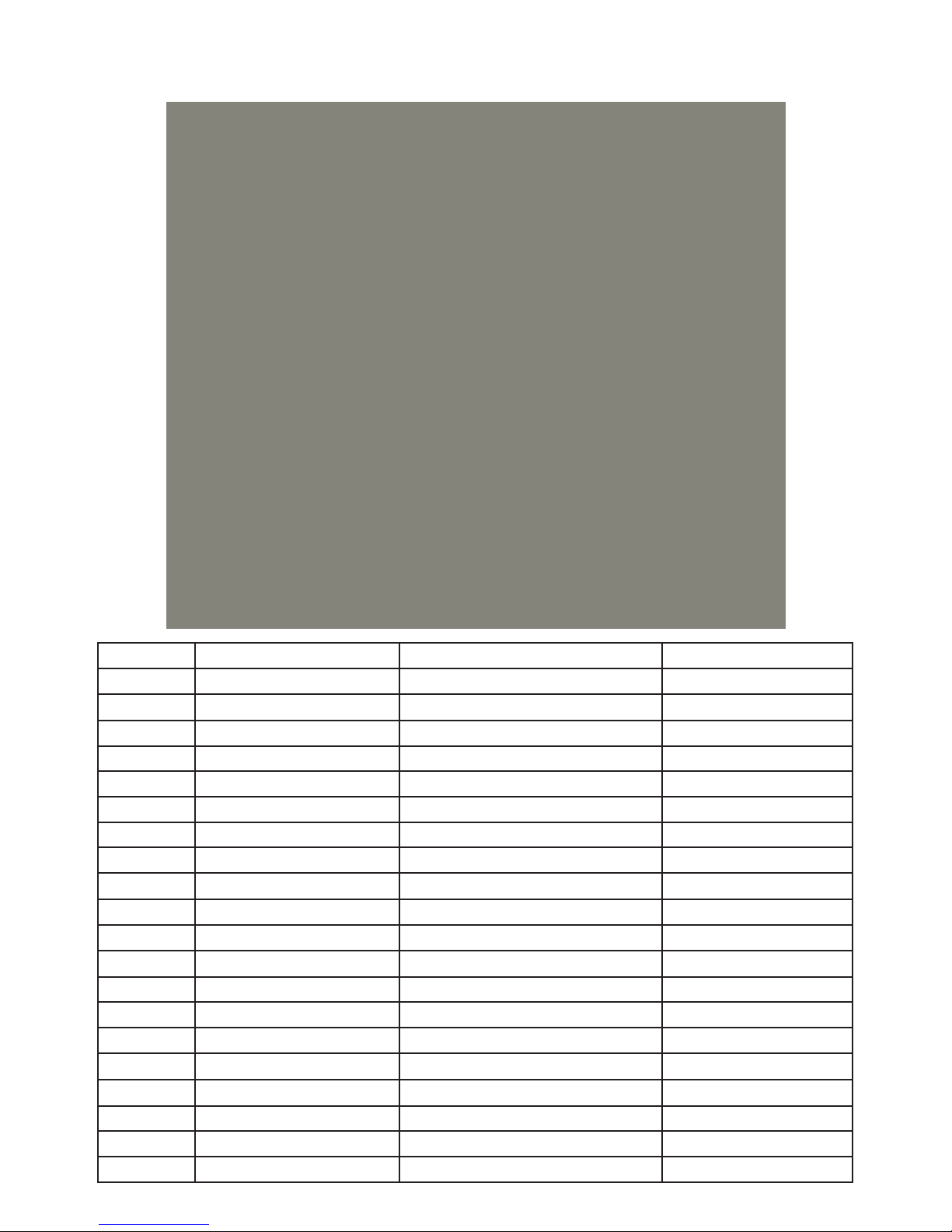
CLEANER PARTS
A
A
A
22
ADMIRAL ULTRA (NC71AU)
LOCATION PRODUCT # DESCRIPTION
1 NC7115 TOP HELL
2 NC7106 LOWER CHA I
3 NC7122AU POWER UPPLY
4 NC7123 CABLE
5 NC7107 DRIVE MOTOR
6 NC7113 PUMP MOTOR
7 NC1004 DRIVE BRU H
8 NC7108 DRIVE WHEEL TUBE
9 NC7112 NON DRIVE WHEEL TUBE
10 NC7104 BRU H MOUNT WITH BEARING (L/R IDE )
11 NC7116 TRACK ( ET OF 2)
12 NC7117 TRACK WHEEL ( ET OF 6)
13 NC7105 CABLE TRAIN RELIEF
14 NC7118 TRACK WHEEL COVER (L/R IDE )
15 NC7109 HANDLE
16 NC7110 IMPELLER COVER
17 NC7103 BRU H CENTER BRACKET
18 NC7119 UPPER/LOWER GA KET EAL
19 NC7111 INNER DRAIN FLAP
20 NC7120 FILTER BAG
21 NC7102 BOTTOM LID
22 NC7101 BOTTOM LID DOOR
23 NC7114 QUICK DRAIN FLAP
3
NC32AU & NC52AU
CLEANER PARTS
ADMIRAL (NC32AU) ADMIRAL PLUS (NC52AU)
LOCATION PRODUCT # PRODUCT # DESCRIPTION
1 NC1001:02 CHA I
2 and 2A NC1009:02 NC1024:02 PUMP MOTOR
3 and 3A NC1013AU NC1023AU POWER UPPLY
4 NC1012:02 FLOATING CORD
5 NC1006:02 DRIVE MOTOR
6 NC1010 DRIVE TUBE MOUNT
7 NC1011 CHA I BUMPER
8 NC1002 EN OR WHEEL TIRE
9 NC1005 QUICK DRAIN FLAP
10 NC1017 FILTER BAG
11 NC1003 IMPELLER COVER
12 NC1008 HANDLE
13 NC1004 DRIVE BRU H
14 NC1014 FOAM RING
15 NC1007 DRIVE WHEEL TUBE
16 NC1016 BOTTOM LID
17 NC1018 FRONT INTAKE
18 NC1019 REAR INTAKE
19 NC1015 IMPELLER

4
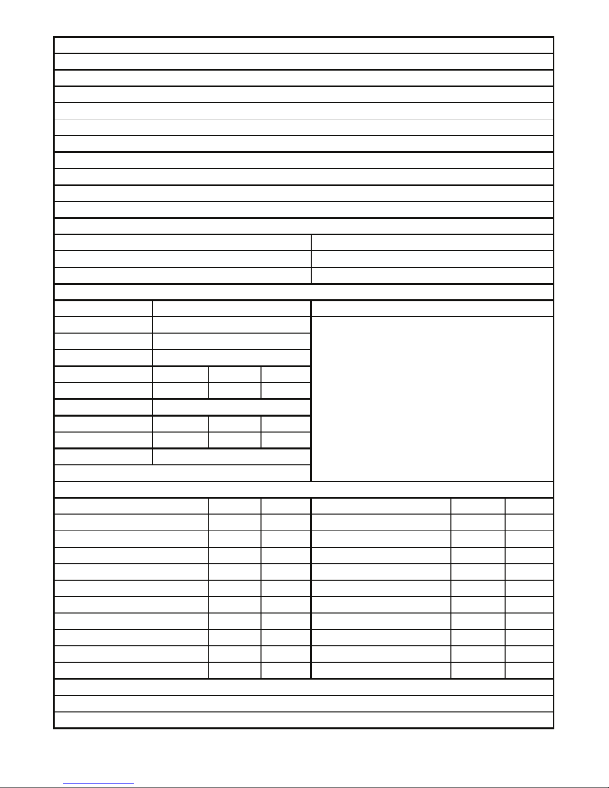
RA: Received:
Service Center Location:
Customer:
Phone: Email: Date of Purchase:
Y N Partial Authorized By:
Serial Number:
Used Misuse ------------
------------
Water Entry Motor Programming
Other:
Part # Qty Part # Qty
NC7102 Non Drive Wheel Tube NC7112
NC7103 Pump Motor NC7113
NC7104 Top Return Flap NC7114
NC7105 Top Shell NC7115
NC7106 Tracks NC7116
NC7107 Track Wheels NC7117
NC7108 Track Wheel Covers NC7118
NC7109 NC7120
NC7110 NC7122AU
NC7111 Cable NC7123
Test 1 Tank Number: Time In: Time Out: Pass Fail
Test 2 Tank Number: Time In: Time Out: Pass Fail
Sensor Wheel
Parts
Power Supply
Pump Motor
(select one)
Handle
Cable Strain Relief
Chasis
Cable
Drive Motor
Filter Bag (Installation)
NFF
Warranty Approval:
Description
Description
Items Received
Fault (mark all that apply)
Technician:
Date of Evaluation:
Power Supply Filter Bag Bottom Lid Caddy (Complete: Y N)
Comments
(select one)
Wall Scrubber/Scrubber 60/Admiral Ultra
Please complete and fax or email this form (Along with Proof of Purchase) to: 732-719-9146/[email protected]
Address: City: State: Zip:
Power Supply
Part
Defective
Filter Bag
Bottom Lid
Brush Center Bracket
Smartpool Use Only
Water Test
Voltage from Power Supply: Vdc
Voltage to Pump Motor: Vdc
Voltage to Drive Motor: Vdc
Voltage through Cable: Vdc
Impeller Cover
Brush Mount with Bering
Drive Motor
Drive Wheel Tube
Inner Quick Drain Flap
5
RA: Received:
Service Center Location:
Customer:
Phone: Email: Date of Purchase:
Y N Partial Authorized By:
Serial Number:
Used Misuse ------------
------------
Water Entry Motor Programming
Other:
Part # Qty Part # Qty
NC1001:02 Foam Ring NC1014
NC1003 Impeller NC1015
NC1004 Bottom Lid NC1016
Drive Motor Version 2 NC1006:02 Filter Bag NC1017
Drive Wheel Tube NC1007 Front Intake NC1018
NC1008 Rear Intake NC1019
NC1009:02 Power Supply (Wall Climber) NC1023AU
NC1010 Pump Motor (Wall Climber) NC1024:02
Floating Cord 50' Version 2 NC1012:02 Other
Power Supply (Wall To Wall) NC1013AU Other
Test 1 Tank Number: Time In: Time Out: Pass Fail
Test 2 Tank Number: Time In: Time Out: Pass Fail
Defective
Drive Motor
Pump Motor
Sensor Wheel
(select one)
(select one)
Filter Bag (Installation)
Water Test
Voltage from Power Supply: Vdc
Voltage to Pump Motor: Vdc
Voltage to Drive Motor: Vdc
Voltage through Cable: Vdc
Drive Brush
Pump Motor (Wall to Wall) Version 2
Drive Motor Mount
Cable
Comments
Chassis
Impeller Cover
Handle
Nitro/Admiral/Admiral Plus
Please complete and fax or email this form (Along with Proof of Purchase) to: 732-719-9146/[email protected]
Address: City: State: Zip:
Power Supply Filter Bag Bottom Lid
Warranty Approval:
Smartpool Use Only
Cleaner/Items Received
Fault (mark all that apply)
Technician:
Date of Evaluation:
Description
Description
Part
Parts
NFF
Power Supply
6
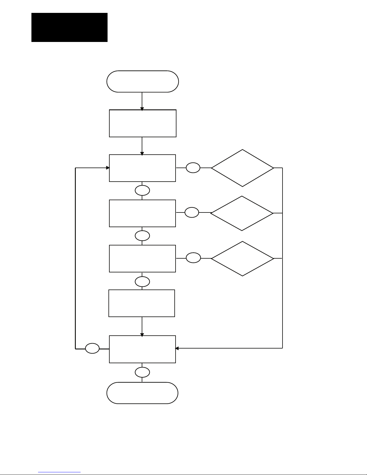
NC71AU Troubleshooting Guide
Model:
Scrubber/Admiral Ultra
Tes t
Cable
(26-29Vdc)
Tes t
Power Supply
(29-32Vdc)
Replace
Drive Motor
Replace
Cable
Replace Pump Motor
Remove any debris from
impeller or tracks and
check for damage.
Tes t
Drive Motor with Test
Cable (OK)
Replace
Power
Supply
Water Test
(OK)
Return to Customer
N
Y
Y
N
Y
N
Y
N

7
Smartpool Robotic Cleaner Troubleshooting Guide
Models:
Nitro/Admiral/Admiral Plus
Test
Cable
(25-28Vdc)
Test
Power Supply
(28-32Vdc)
Self Test
(OK)
Filter Bag Properly
Installed
Replace
Power
Supply
Water Test
(OK)
Replace
Cable
Return to Customer
Test
Pump Motor
(25-28Vdc)
Replace
Pump Motor
Test Drive Motor
(18-23Vdc)
Remove any debris from
impeller or tracks and
check for damage.
Install Filter
Bag
correctly
Replace
Drive Motor
Y
N
Y
Y
N
Y
N
N
N
Y
Y
Y
N
If Necessary:
Test
Sensor Wheels
(Circuit Open/Close)
Replace
Chassis
N
Water Test
(OK)
Y
N
Y

www.smartpool.com
8
SCRUBBER SERIES EVALUATION
Model Number:
NC71AU

www.smartpool.com
9
1) Place the cleaner on the bench and
examine for physical damage and for any
debris caught in the impeller or drive
brushes (remove debris if found).
2) Place the cleaner upside down on bench
and remove the Bottom id by pushing in
on the red tabs.
3) Perform a Self Test: Plug Cable into the
Power Supply and turn to the ON position.
Important: The Pump Motor will engage
but the Drive Motor will not (An Air Flow
Sensor in the Pump Motor prevents the
Drive Motor from operating out of water).

www.smartpool.com
10
• If the cleaner is “Dead In ater” or has “No Suction/Does Not Pick Up Debris” then the
unit should not move at all during the self test.
• If the cleaner is “Spinning in Circles” or “Does Not Move” then the impeller should operate
during the self test.
RESULTS
Table of contents
Other SmartPool Swimming Pool Cleaner manuals


