Instructions for the installer
7
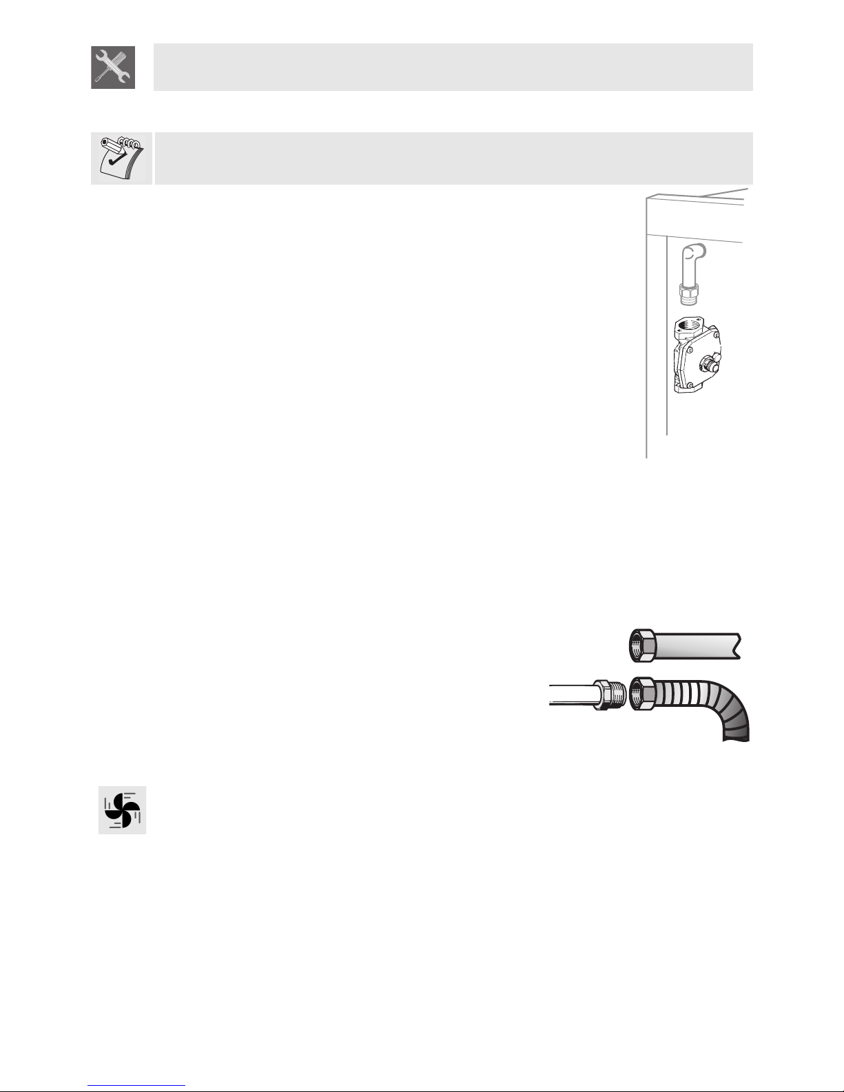
2.3 Gas connection
Always use a suitable sealing substance (such as teflon tape) between the gas connection.
This appliance is suitable for installation with Natural Gas or ULPG (propane). Refer
to page 13 for the relevant burner pressure and appropriate injector sizes. When the
appliance is to be connected to Natural Gas then the pressure regulator supplied
must be fitted to the gas inlet. A test point (for checking the gas pressure) is supplied
either with the regulator or as a separate fitting in the case of LPG (propane)
appliances.
Connection of the appliance to the gas supply must be in accordance with the
requirements of AS5601. A ½” BSP connector at the inlet is recommended and the
gas supply line to the appliance must be of adequate length to allow sufficient
withdrawal of appliance for service or disconnection and be:
1 annealed copper pipe or;
2 Flexible hose according to AS/NZ1869 & be at least Class “B”, 10 mm diameter,
max length 1000 mm.
The cooker must be installed with provision to allow the gas to be turned off and
disconnected for servicing and removal of the appliance as required from the gas
supply.
Before the cooker is operated make certain all relevant parts are placed in the correct
position.
When the installation is completed the installation connections of cooker will require
to be leak tested, the burner operating pressure and flame checked and adjusted.
Warranty service calls do not cover these adjustments!
To check the operating pressure of the appliance it is recommended at least 2 large
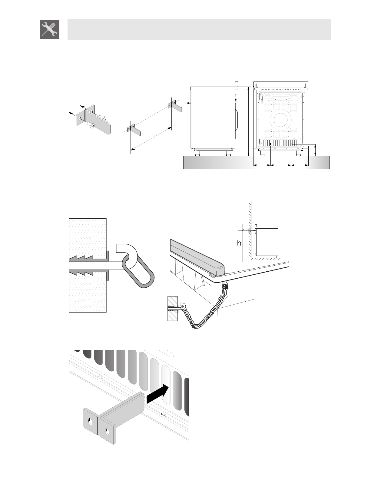
size burners are used. Ensure appliance is secured to wall when installation is
completed.
N.G. A regulator must be fitted to the ½ BSP thread at the rear of the appliance. An
approved manual shut-off valve must be installed. The N.G. regulator must be
checked and adjusted to 1.0kPa after installation.
U.L.P.G. Can be connected to the inlet fitting directly. The pressure
must be checked to ensure it is operating at 2.75kPa. A separate
test point fitting must be installed between the piping & the
appliance for the pressure to be checked to ensure it is operating at
2.75kPa.
2.4 Ventilation requirements
Caution – This cooker may only be installed and operated in rooms permanently ventilated in
accordance with current regulations. For proper operation of a gas appliance it is essential for the air
necessary for combustion of the gas to be able to flow naturally into the room. Air must flow directly into
the room through openings in its outside walls. This (these) opening (s) must have a free passage cross-
section of at least 100 cm2, or 200 cm2 for appliances not equipped with gas safety device. These
openings must be constructed so that they cannot be obstructed indoors or outdoors, and should
preferably be close to the floor on the side opposite to the combustion gas discharge point. If it is not
possible to make the openings in the room where the cooker is installed, the necessary air may be taken
from an adjoining room, proveded it is not a bedroom or a room with fire risk.