EEWH311C 9
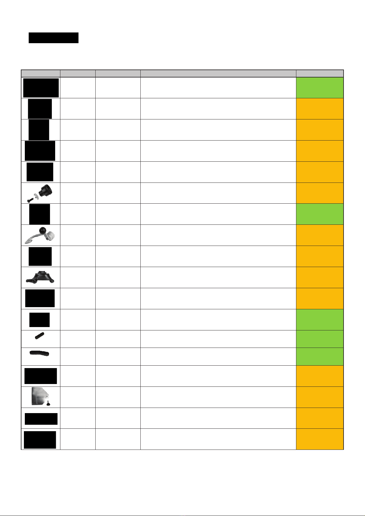
1.2.1 TURNTABLE & CABINET FEATURES
EEWH311C
INTEGRATED BEAD SEATING JETS - Air in!ation jets are integrated into
the turntable clamping jaws to insure full bead seating force directly into the
tire cavity regardless of tire diameter.
3-position Bead Breaker
Position one covers the range of popular tires (3.5” to 13”). Position two
covers many tailer sidewall light truck and SUV tires (4” to 14.5”). Position
three covers the larger wheel diameters with low pro"le performance tires
(4.5” to 15”).
Turntable with Reverse
Forward speed of 7 RPM providing precise control and minimizes tear-
ing of tires. In the event the bead becomes jammed up on lower pro"le
performance tires, the 7 RPM reverse mode quickly relieves the mount/
dismount head to minimize wheel damage from using a prybar.
TWIN CYLINDER CLAMPING POWER - Two 3” clamping cylinders provide
uniform clamping pressure throughout the stroke (regardless of rim sizes)
as well as providing 25% more clamping power than most single clamping
cylinder tire changers. Additionally these two smaller cylinders reduce the
critical turntable to cabinet distance, reducing the stress on the transmission.
WHEEL CLAMPS
UNIQUE FIFTEEN POINT CONTACT CLAMPS
Provide better gripping capability regardless of dirt and moisture.
REDUCED ANGLE CLAMPS
Increases clamping contact area with rim insuring no slippage.
NYLON INSERT SOFT TOUCH CLAMPS
The two front and rear insert in the clamping jaws provides Nonmetal touch
in critical customer visible areas.
VALVE CORE/TIRE TOOL STORAGE CABINET
On tire changer storage area for valves, tools, caulk, etc.
INCOMING AIR PRESSURE GAUGE
Ergonomically located air gauge allows easy operator monitoring of incoming
air pressure.
INTEGRATED PRESSURE LIMITER
Integrated safety pressure limiter stops air !ow once tire pressure has
reached approximately. 55 PSI preventing accidental tire over-in!ation.
MOUNT/DEMOUNT ARM ASSEMBLY
ADJUSTABLE SLIDEWAY - Unique adjustable vertical mount/demount hex
shaft slideway allows for easy operator adjustment to compensate for any
cumulative wear in the slideway causing mount/demount head movement.
NON-SCRATCH NYLON INSERT - Integrated into the mount/demount head
is a replaceable scratch resistant nylon insert protecting against accidental
rim contact.
CONSTRUCTION DESIGNED FOR DURABILITY
RUST PROOF VALVES AND CYLINDERS - Critical bead breaking cylinder
is lined with rustproof poly"ber liner for years of rust free operation. Non-lined
cylinders will pit causing bead breaker power loss.
LIFETIME LUBRICATED POLYMER VALVES - Critical foot valves fabricated
from glass/"ber self-lubricating material providing years of maintenance
free operation.
WATER SEPARATOR AND AUTOMATIC OILER - Lubricates all air used
for machine operation, does not lubricate air used for tire in!ation, as do
some competitive models.
HIGH TORQUE 1HP MOTOR - Industrial strength high torque turntable drive
motor eliminates tire remount stalling on low pro"le high performance tires.
TRANSMISSION - Designed for extremely heavy use, the critical motor to
turntable transmission linkage carries a full two (2) year replacement warranty.
PNEUMATIC BEAD ASSIST ARM
Up/Down Control Switch - Toggle switch allows single "nger operation of
all pneumatic PBA functions, with or without gloves.
Top Bead Roller - Provides easily controlled pneumatic power to drive
upper beads down into the wheel drop center (while tire is turning) for easy
lubrication prior to dismounting. Also provides pneumatic power assistance
for safely remounting second bead on extremely low pro"le and Run Flat
design tires.
Bead Depressor - Provides easily controlled pneumatic power to depress
the tires sidewall during the remount cycle. This will prevent premature bead
seating before the entire bead has been reinstalled on the wheel. Provides
an added level of safety by keeping the technicians hands away from the
bead area during this potential pinch point procedure. Additionally the Bead
Depressor “follows” the tire around while turning to guarantee successful
remount "rst time every time.
Bottom Bead Roller - Provides easily controlled pneumatic power to unseat
stubborn lower beads which may have accidentally reseated after the original
bead breaking procedure. Also allows a technician to raise and hold wider
tires up, to assist in safely and easily getting the second bead up onto the
mount/demount head.
Wheel Centering Depressor - Provides downward pressure on a rim when
working to clamp a low pro"le tire/rim combination. Will assist the technician in
correctly seating the rim clamps between the tire and the rim when clamping
from outside in where it is dif"cult to depress the tire sidewall enough to expose
the rim edge.
SAFETY RESTRAINT ARM (OPTIONAL)
TIRE/RIM ASSEMBLY RESTRAINT - Safety Restraint Arm restrains tire
and rim assembly to the tire machine during the in!ation process reducing
potential for injury caused by the unlikely event of catastrophic tire or rim
failure.
SIMPLE SWING ARM DESIGN - SRA arm easily swings to the left when
not in use, allowing the technician to quickly and safely perform the in!ation
process without disrupting the tire changing procedure.
GRAVITY LOCK - SRA lock mechanism operates without any mechanical
cam system eliminating the possibility of system deterioration or mis-
adjustment from mechanical wear.
POSITIONING SAFETY INTERLOCK SWITCH - Integrated switch insures
that SRA arm is centered on the tire/rim assembly before the in!ation process
can begin.
ANTI-ROTATION LOCK - Prevents SRA from rotating horizontally during
in!ation process.