Snell IQMDA00 User manual

IQMDA00 SECTION N1
IQMDA00OPS 090305 www.snellwilcox.com Version 1 Issue 2 N1.1
IQMDA00 HD/SD-SDI distribution amplifier and
HD-SDI monitoring downconverter
Module Description
The IQMDA00 is an HD/SD-SDI distribution
amplifier and HD-SDI monitoring downconverter.
This module takes HD-SDI streams and produces
four re-clocked HD-SDI outputs. It also converts
the input signal to same frame-rate SD-SDI
outputs for monitoring. Output options include 4 x
HD-SDI and 3 x SD-SDI. One group of audio can
also be carried through from the HD inputs to the
SD outputs. This module can also be used to
distribute SD-SDI signals to SMPTE 259M-C,
providing 7 outputs from one input.
Rear Panel View
SD-SERIAL OUT
2
1
4
3
2
1
HD-SERIAL OUT
IQMDA
0026-1A
SERIAL IN
3
Versions of the module cards available are:
IQMDA0026-1A HD/SD-SDI DA and HD-SDI Monitoring Down-converter. 4 HD-SDI and 3 SD-SDI outputs
Note that this module can only be fitted into the ‘A’ Style Enclosure shown below.
(Enclosure order codes IQH3A-E-0, IQH3A-E-P, IQH3A-0-0, IQH3A-0-P)
C
C
IQMDA00 SECTION N1
IQMDA00OPS 090305 www.snellwilcox.com Version 1 Issue 2 N1.2
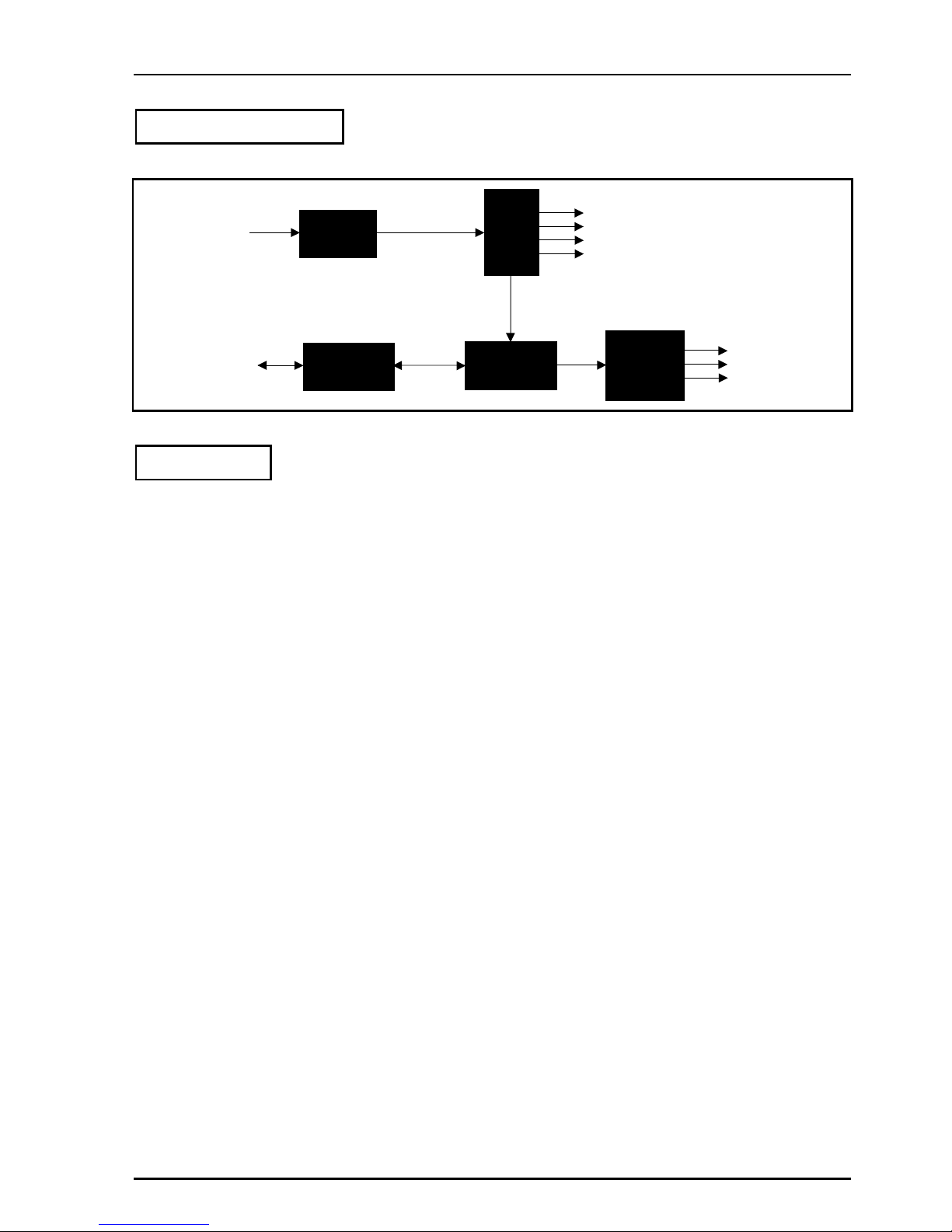
Block Diagram
Reclock
and
Output
Drivers
Serial
Outputs
Input
Equalizer
Serial
Input
Deserialize
CRC/EDH
Check
Processor
RollCall
Monitoring
Down
Conversion
Serial
Outputs
Features
•An HD-SDI monitoring down-converter to allow compact low-cost, low-power monitoring solutions for HD
environments
•Standards supported:
♦HD-SDI to SMPTE292M
♦SD-SDI to SMPTE259M-C
•A distribution amplifier for HD-SDI signals with SD-SDI monitoring capability
•A distribution amplifier for SD-SDI signals with 7 x SD-SDI outputs
•Audio capability means that a complete Audio/Video monitoring solution is possible
•Supports one output group of embedded audio channels with input audio group selection
•Monitoring output aspect ratio may be set to letterbox, anamorphic or center cut out picture modes
•Signal loss detection
•Maintains the input frame-rate for the output signal
•RollCall remote control and monitoring compatible

IQMDA00 SECTION N1
IQMDA00OPS 090305 www.snellwilcox.com Version 1 Issue 2 N1.3
Technical Profile
Features
Signal Input
Electrical ........................... 1.5 Gbit/s HD-SDI, SMPTE 292M
270 Mbit/s SDI, SMPTE 259M-C
Connector / Format ............ BNC/ 75 Ohm panel jack on
standard S&W connector panel
Input Cable Length............. Up to 140 m Belden 1694A @
1.5 Gbit/s
Up to 350 m Belden 1694A @
270 Mbit/s
Return loss......................... > -15 dB
Distribution Outputs
Electrical ........................... 1.5 Gbit/s HD-SDI, SMPTE 292M
270 Mbit/s SDI, SMPTE 259M-C
Connector / Format ............ BNC/ 75 Ohm panel jack on
standard S&W connector panel
Outputs .............................. 4
Return loss ............................. > -15 dB
Downconverter Outputs
Electrical ............................ 270 Mb/s SD-SDI SMPTE 259M-C
including one group of embedded
audio, delayed to match the HD/SD
video processing delay
Connector / Format ............ BNC/ 75ohm panel jack on
standard S&W connector panel
Outputs .............................. 3
Output Return Loss............ > -15 dB
Indicators
Power ................................ OK
CPU................................... OK
Status ................................ OK (Green)
Warning (Yellow)
Error (Red)
Available Conversions
Input Output
1125(1080)/29.97i or sF 525(483)/29.97i
1125(1080)/25i or sF 625(576)/25i
750(720)/59.94P 525(483)/29.97i
750(720)/50P 625(576)/25i
625(576)/25i 625(576)/25i
525(483)/29.97i 525(483)/29.97i
RollCall Control
1. Control
2. Aspect ratio for monitoring outputs
letterbox, anamorphic, center cut out
User Memories................... 16 x Save / Recall / Rename
Input audio group selection Groups 1 to 4
Reporting ........................... Input format(including unknown),
input loss, CRC error
Logging .............................. Input Status
Input Standard
Convert
CRC/EDH
CRC/EDH total
RollTrack Controls.............. On/Off, Index, Source, Address,
Command, Status, Sending.
RollTrack Outputs .............. Unused
SD Output Video Delay
Input Present
Input Loss
Specifications
Processing......................... 10 bit
Under/over shoot ............... <10%
Linearity ............................. ±1 LSB
S/N .................................... > 65 dB
Color Space ....................... Transmission matrix conversion
from SMPTE274 to ITUR-601
Y/C delay ........................... < 10 ns
SD Output Delay................ 1 output Frame
625(576)/25i = 40 ms
525(483)/29.97i = 33 ms
No conversion = 0 ms
With SD inputs = 1.2 µs
Horizontal Response (anamorphic)
±0.2 dB to 5.4 MHz, > 45 dB stop
band attenuation
Vertical Response.............. > 40 dB stop band attenuation
Power Consumption
Module Power Consumption
8.5 W Max
IQMDA00 SECTION N1
IQMDA00OPS 090305 www.snellwilcox.com Version 1 Issue 2 N1.4
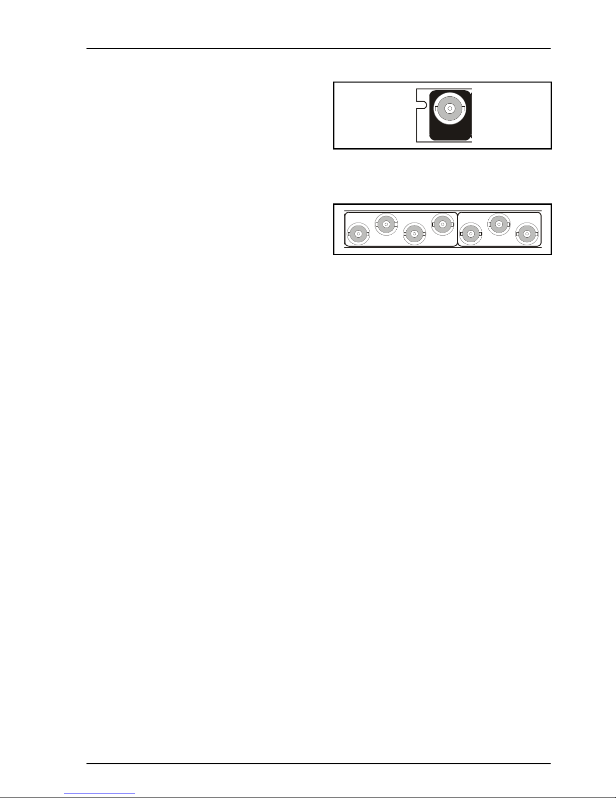
INPUTS
Serial Digital Video Input
The serial digital input to the unit is made via this
BNC connector which terminates in 75 Ohms.
OUTPUTS
HD-Serial Out
These are the four HD distribution serial digital
outputs of the unit via 75 Ohm BNC connectors.
Note that for SD serial inputs these connectors will
provide four SD distribution serial digital outputs.
SD-Serial Out
These are the three downconverted HD serial
digital outputs of the unit via 75 Ohm BNC
connectors. These outputs also include one group
of embedded audio (if present in the source
signal), automatically delayed to match the HD/SD
processing delay
Note that for SD serial inputs these connectors will
provide three SD distribution serial digital outputs.
IQMDA
0026-1A
SERIAL IN
SD-SERIAL OUT
2
1
4
3
2
1
HD-SERIAL OUT
3

IQMDA00 SECTION N1
IQMDA00OPS 090305 www.snellwilcox.com Version 1 Issue 2 N1.5
CARD EDGE CONTROL
Power OK
CPU OK
OK
Warning
Erro
r
LED INDICATORS
Power OK (Green)
This indicator is illuminated when the positive
supply is present.
CPU OK (Green)
This LED will flash to indicate that the CPU is
running.
Error (Red)
This will only become illuminated when CRC/EDH
errors are being detected on the input or with no
input present.
Warning (Yellow)
This will only become illuminated when the unit
cannot convert the HD input to a SD output.
OK (Green)
When illuminated this will indicate that the module
is locked to the input signal.
Power OK
CPU OK
OK
Warning
Erro
r

IQMDA00 SECTION N1
IQMDA00OPS 090305 www.snellwilcox.com Version 1 Issue 2 N1.6
RollCall PC Control Panel Screens for the IQMDA00
Input & Output
This screen allows the input and output settings to
be selected.
Output (Standard)
This allows the standard of the monitoring output to
be selected.
Auto
When Auto is selected the standard of the SD
monitoring output will be at the same frame-rate as
the HD input signal if the conversion is valid (see
the Valid Conversions table).
Note that if the conversion is not valid then
OUT: Can't Convert will appear in the Unit Status
line.
625/25i
The standard of the SD monitoring output will be
forced to 625/25i. (See the Valid Conversions
table).
525/29i
The standard of the SD monitoring output will be
forced to 525/29i. (See the Valid Conversions
table).
Valid Conversions
Input Output
1125(1080)/29.97I or sF 525(483)/29.97i
1125(1080)/25I or sF 625(576)/25i
750(720)/59.94P 525(483)/29.97i
750(720)/50P 625(576)/25i
625(576)/25i 625(576)/25i
525(483)/29.97i 525(483)/29.97i
On Input Loss
This controls the system response to a loss of
input signal.
Input
The incoming signal will be displayed whenever
possible.
Black
When an input loss is detected the output picture
will cut to black.
75% Color bars
When an input loss is detected the output picture
will become a 75% color bars pattern.

IQMDA00 SECTION N1
IQMDA00OPS 090305 www.snellwilcox.com Version 1 Issue 2 N1.7
Input & Output (continued)
Output Format
This allows the aspect ratio of the output picture to
be selected from the list as follows:
•Letterbox Center
To maintain the correct shape of objects on the
16:9 input, this displays the 16:9 picture as a strip
across the center of the 4:3 display.
•Anamorphic
This setting retains all picture information from the
input and passes it to fill the output image
regardless of the aspect ratio conversion. This
means that 16:9 to 4:3 conversions will appear
squeezed horizontally.
•Center Cut-out
To maintain the correct shape of objects on the
16:9 input, this setting retains all vertical detail but
crops the left and right edges of the image.
•Letterbox Top
To maintain the correct shape of objects on the
16:9 input, this displays the 16:9 picture as a strip
at the top of the 4:3 display.
•Letterbox Bottom
To maintain the correct shape of objects on the
16:9 input, this displays the 16:9 picture as a strip
at the bottom of the 4:3 display.
•L-Box Screen Saver
In this mode the picture, in letterbox format, will
slowly move up and down on the screen.
Input 16:9 Transformation Output 4:3
Center Cutout Image is side
cropped
Anamorphic Image is squeezed
horizontally
Letterbox Center
Letterbox Top
Letterbox Bottom
Letterbox Screen
Saver

IQMDA00 SECTION N1
IQMDA00OPS 090305 www.snellwilcox.com Version 1 Issue 2 N1.8
Input & Output (continued)
Output Pattern
ON
When checked the output will become the pattern
selected from the Pattern Type item.
Pattern Type
This allows will allow either Black or 75% Color
Bars to be used as the output signal when the ON
item has been checked.
Audio Output Group 1
One group of audio can be carried through from
the HD input to the SD outputs.
This item allows one of the input groups to be
selected.
CRC/EDH
This item provides information about the Cyclic
Redundancy Checksum errors or EDH errors
within the input.
CRC/EDH
This will display the current CRC/EDH Error Rate.
CRC/EDH Total
This will display the total CRC/EDH Error Count
since the last reset.
This will reset the CRC/EDH error counter to zero.
IQMDA00 SECTION N1
IQMDA00OPS 090305 www.snellwilcox.com Version 1 Issue 2 N1.9
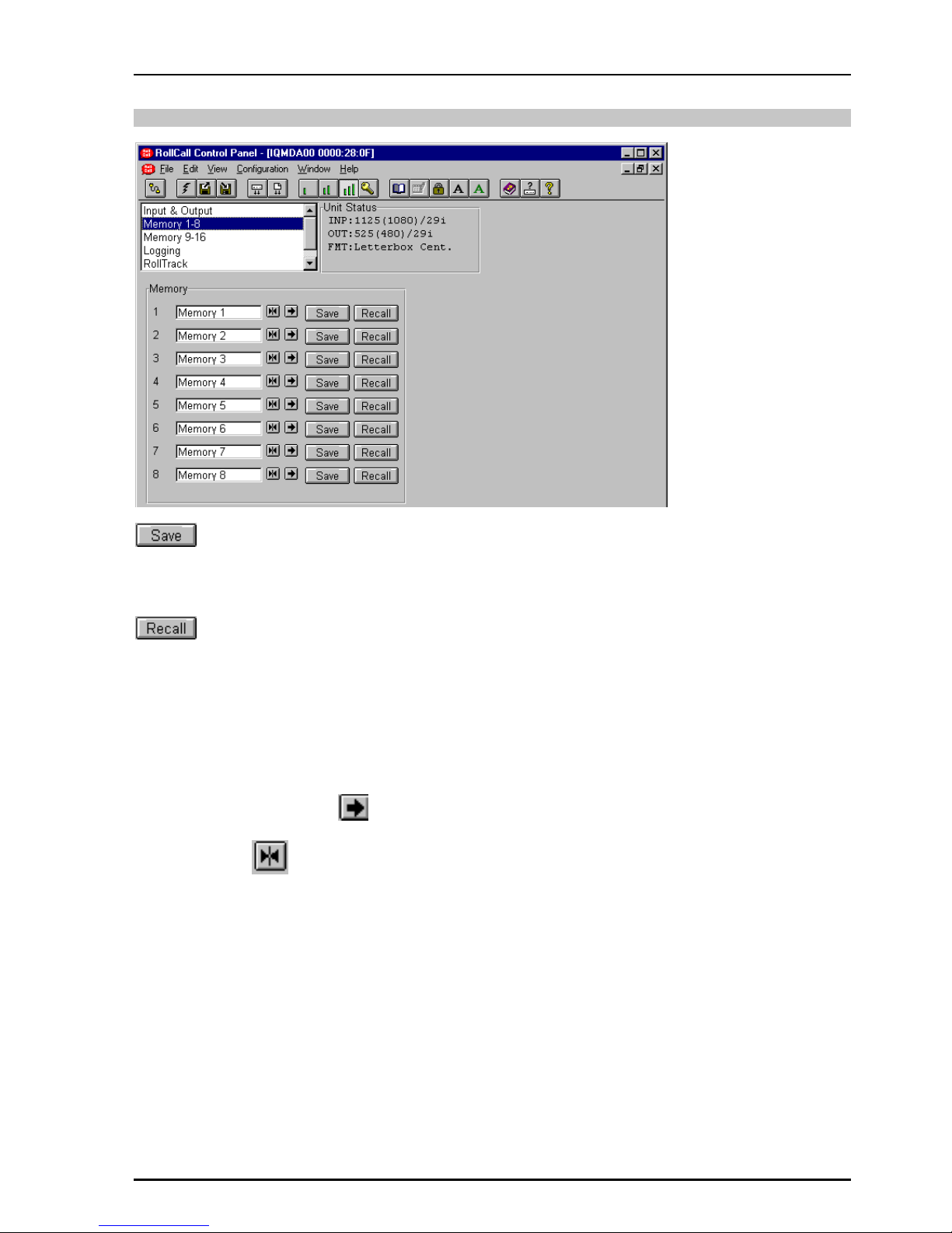
Memory 1-8 and 9-16
(Memory 1-8 and 9-16)
This item will store the settings in the selected
memory location.
(Memory 1 to 8 and 9-16)
This item will recall the settings from the selected
memory location.
Memory 1 to 8 and 9-16
The memory location name may be renamed.
To change the memory name, type the new name
in the text area and then select (return).
Selecting Preset will return the text to the
default name (Memory 1-8 and 9-16).

IQMDA00 SECTION N1
IQMDA00OPS 090305 www.snellwilcox.com Version 1 Issue 2 N1.10
Logging
Information about various parameters can be
made available to a logging device that is attached
to the RollCall™ network by checking the
appropriate box.
The status is shown to the right of the item.
Any of the items may be selected from the list.
ROLLCALL LOG FIELDS
Log Field Log Value Description
INPUT LOST No input present.
OK Input present is OK.
STD <string> Input standard description.
CONVERT OK Valid conversion available.
NONE No valid conversion available.
CRC_ERR <number> A number stating the current CRC/EDH error rate.
CRC_ERR_TOTAL <number> A number stating the total number of CRC/EDH errors that
have been received since the last reset.
SN <string> Serial Number of unit.

IQMDA00 SECTION N1
IQMDA00OPS 090305 www.snellwilcox.com Version 1 Issue 2 N1.11
RollTrack
This function allows information about the status of
the module to be communicated to other RollTrack
compatible units connected to the network. This
message can then be used to cause another unit
to perform a specific action. For example, it can be
used to control the switching of a router or
changeover module on loss of input.
Disable All
When this item is checked all RollTrack items will
be disabled.
Index
There are 16 (1 to 16) RollTrack destinations
available. This item is used to select which
RollTrack Index is set up using the RollTrack
Source, RollTrack Address and RollTrack
Command functions.
Source
This selects the source of information that triggers
the transmission of the RollTrack data.
Options are:
Unused (off &Preset)
SD O/P Video Delay
Input Present Input signal is present
Input Loss Input signal is lost
The destination for the information is set by the
network code address as follows:
Address:ID
This item allows the address of the destination unit
to be set.
To change the address, type the new destination in
the text area and then select (return)
(Preset) returns to the default destination
The full RollTrack address has four sets of
numbers. For example: 0000:10:01*99
The first set (0000) is the network segment code
number.
The second set (10) is the number identifying the
enclosure/mainframe.
The third set (01) is the slot number in the
enclosure.
The fourth set (99) specifies which type of unit will
respond to the command. For example setting to
158 will ensure only an IQDRT8 will respond. This
feature can be used to protect against a different
type of unit responding incorrectly.
Setting to 00 allows any type of unit to respond to
the command.
For a list of unit IDs, please contact your local Snell
& Wilcox agent.
Command Value
The full RollTrack command has two sets of
numbers. For example: 84:156
The first set (84) is the RollTrack command number.
The second set (156) is the value sent with the
RollTrack command number.

IQMDA00 SECTION N1
IQMDA00OPS 090305 www.snellwilcox.com Version 1 Issue 2 N1.12
RollTrack (continued)
RollTrack Sending
This item shows when the unit is actively sending
the RollTrack command.
This may show:
String A string value is always being sent.
Number A number value is always being sent.
No The message is not being sent.
Yes The message is being sent.
Internal Type Error
Inconsistent behavior; please contact your local
Snell & Wilcox agent.
RollTrack Status
This item will show the status of the RollTrack
system.
For details of the RollCall command values for
specific units please contact your local Snell &
Wilcox agent.

IQMDA00 SECTION N1
IQMDA00OPS 090305 www.snellwilcox.com Version 1 Issue 2 N1.13
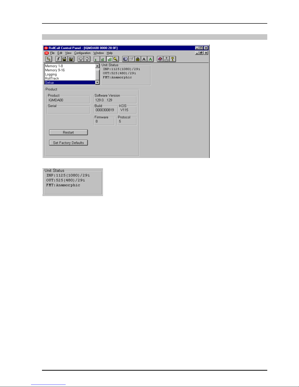
Setup
Product
This shows the name of the unit.
Serial
This will show the serial number of the unit.
Software Version
This shows the software release version number.
Build
This will indicate the factory build number. This
number defines all parameters of the unit (software
versions, build level etc.) for identification
purposes.
Firmware
This shows the version of the firmware system.
Protocol
This shows the protocol identification number.
This will reboot the unit simulating a power-down
power-up cycle restoring power-up settings.
Selecting this item returns all adjustment functions
that include a preset facility, to their factory default
values.
IMPORTANT NOTICE
This function will also clear all the saved
memory settings and return them to the
factory values.
IQMDA00 SECTION N1
IQMDA00OPS 090305 www.snellwilcox.com Version 1 Issue 2 N1.14
Setup (continued)
The Information Window
This will show the status of the unit on four lines of
text.
Line 1
This will show the status of the input signal. It may
show:
INP:<Input Loss!> Loss of input signal
INP:1125(1080)/29i The Input standard
Line 2
This will show the output signal standard e.g.
OUT: 525(480)/29i
Line 3
FMT:Anamorphic
This will show the output format settings i.e. aspect
ratio.
IQMDA00 SECTION N1
IQMDA00OPS 090305 www.snellwilcox.com Version 1 Issue 2 N1.15
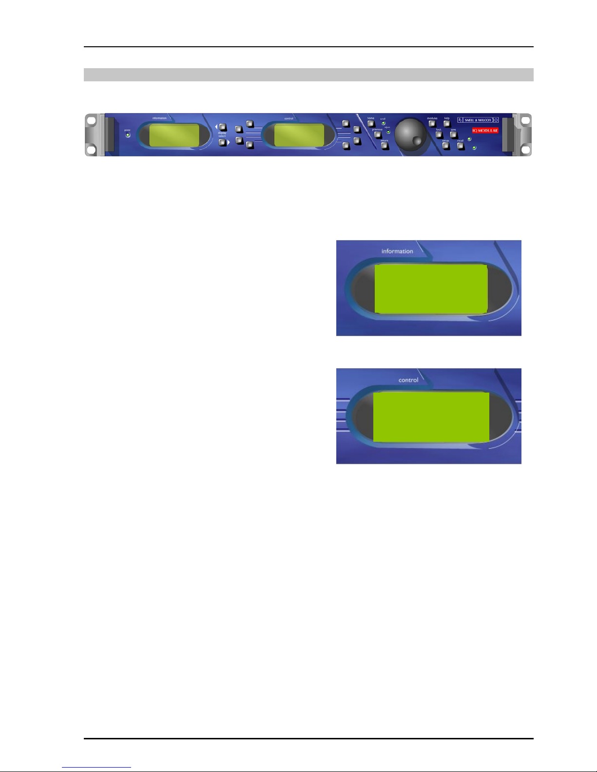
Operation from an Active Control Panel
The card may be operated from an active control panel via the RollCall™ network.
All operational parameters and selections are
made using a system of menus displayed in two
LCD windows.
Operational details for the remote control panel
can be found in the Modular System Operator's
Manual.
Information Window
The Information window has four lines of text
indicating the current state of the unit.
For details of the abbreviations used please see
page 10.
Control Window
The Control window displays all Selection Menus
and sub-menus.
The selection is made by pressing the button
adjacent to the required item.
The menu structure is detailed in the following
pages.
03:IQMDA0
INP: OK CRC:OK
STD:1125(1080)/30i
MAN HD-SDI
◀
◀◀
◀I/P+O/P Memories… ▶
▶▶
▶
◀
◀◀
◀RollCall… Setup… ▶
▶▶
▶
IQMDA00 SECTION N1
IQMDA00OPS 090305 www.snellwilcox.com Version 1 Issue 2 N1.16
IQMDA00 MENU
I/P + O/P...
RollCall...
Memories...
Setup...
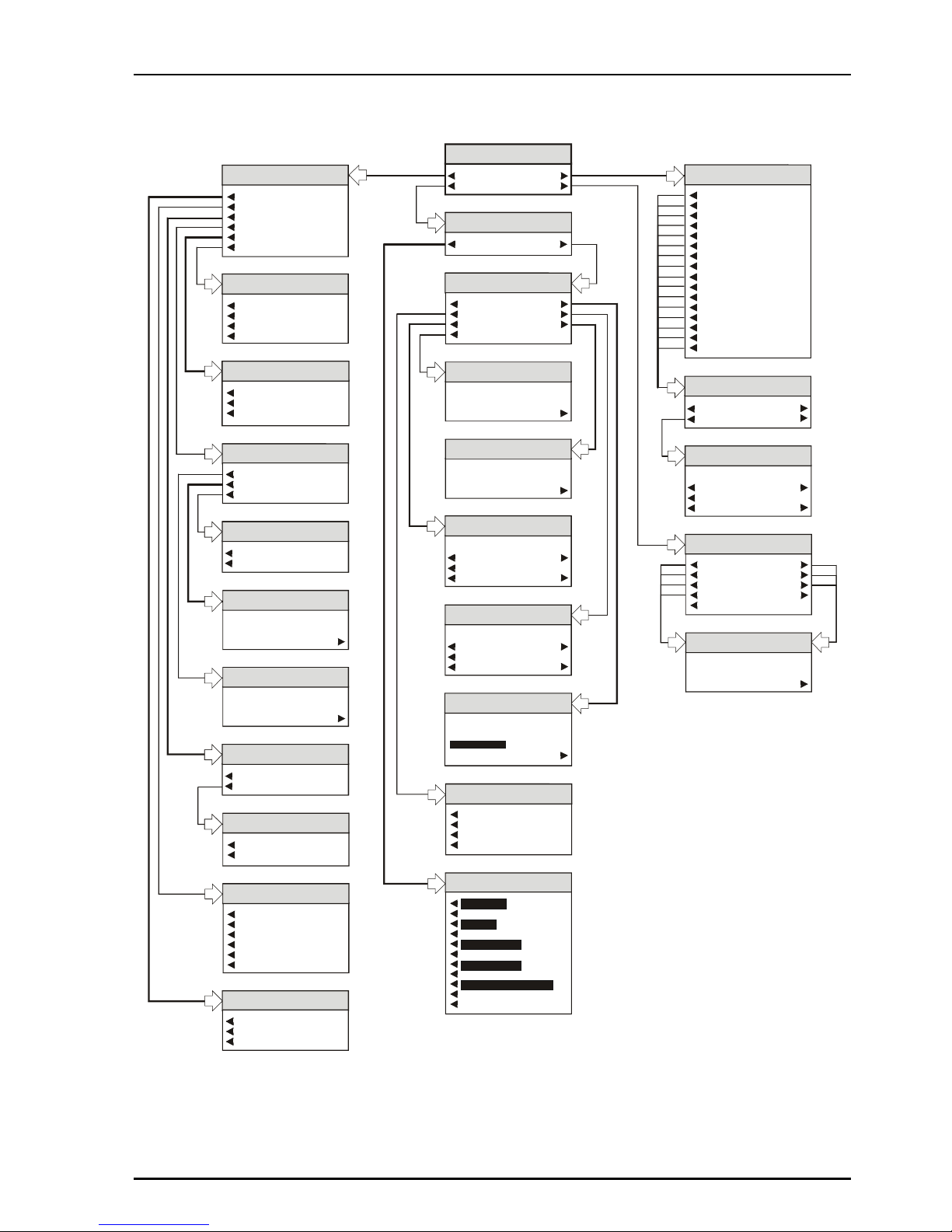
IQMDA00
Menu System
Input
Black
75% Bars
On I/P Loss
Chroma_B/WOutput Format
Letterbox Center
Anamorphic
Center Cut-out
LetterboxTop
Letterbox Bottom
L-Box Screen Saver
Chroma_B/WMemories
Memory 1...
Memory 2...
Memory 3...
Memory 4...
Memory 5..
Memory 6..
Memory 7..
Memory 8...
Memory 9...
Memory 10..
Memory 11...
Memory 12...
Memory 13...
Memory 14...
Memory 15...
Memory 16...
Name Memory 1-16
Name Memory 1-16
Clear
Preset
memory_name
OK
Memory 1 to 16
Save 1-16
Name 1-16
Recall 1-16
CRC/EDH Reset
No
Yes
CRC/EDH Reset
No
Yes
CRC/EDH Reset
No
Yes
Patterns
O/P Pattern
Pattern Type...
Chroma_B/WCRC/EDH
CRC/EDH
CRC/EDH Total
CRC/EDH Reset...
Chroma_B/WOutput Standard
Auto
625/25i
525/29i
CRC/EDH Total Errors
xxxxxxx
OK
CRC/EDH Total (Errors)
CRC/EDH Errors
xxxxxxx
OK
CRC/EDH (Errors)
I/P + O/P
Output Standard...
Output Format...
Patterns...
CRC/EDH...
On I/P Loss...
Audio Grp1...
Pattern Type
Color Black
75% Color Bars
Audio Grp1
Audio Input Grp 1
Audio Input Grp 2
Audio Input Grp 3
Audio Input Grp 4
Index
0
Index
OK
++++++++++++++++++++++++++++++++ +
Chroma_B/WSource
Unused
Video Delay
Input Present
Input Loss
RollCall
Logging... RollTrack...
Sending
xxxxxxx
OK
Sending
Status
xxxxxxx
OK
Status
Chroma_B/WRollTrack
Disable All
Source...
Command
Sending
Index
Address
Status
Command
Command
Clear
Preset
0
OK
Address
Address
Clear
Preset
0
OK Setup Items
xxxxxxx
OK
Setup Items
Setup
Product
SWVersion
Firmware
KOS
Restart
Serial
Build
Protocol
Factory Default
Logging
Log INPUT
Log STD
Log CONVERT
Log CRC_ERR
Lo
g
CRC_ERR_TOTAL
INPUT
STD
CONVERT
CRC ERR
CRC ERR TOTAL
SN
IQMDA00 SECTION N1
IQMDA00OPS 090305 www.snellwilcox.com Version 1 Issue 2 N1.17
MENU DETAILS
(see IQMDA0 Menu System on previous page)
MAIN MENU
The main or top level menu allows various sub-
menus to be selected by pressing the button
adjacent to the required text line.
Note that where a menu item is followed by three
dots (...) this indicates that a further sub-menu may
be selected.
Whenever a menu item is selected the parameters
of that selection will be displayed in the Information
window of the front panel. Where the selection is
purely a mode selection and does not enable a
sub-menu, the text will become reversed (white-on-
black) indicating that the mode is active. If the
mode is not available for selection the text will
remain normal.
Also refer to the block diagram on page 3 for more
information.
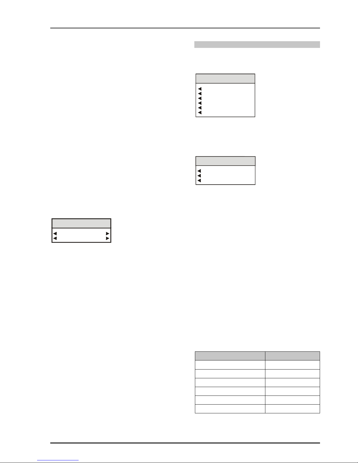
MAIN MENU
IQMDA00 MENU
I/P + O/P...
RollCall...
Memories...
Setup...
◀
◀◀
◀I/P + O/P
This item allows the input and output settings to be
selected.
I/P + O/P
Output Standard...
Output Format...
Patterns...
CRC/EDH...
On I/P Loss...
Audio Grp1...
◀
◀◀
◀Output Standard
This allows the standard of the monitoring output to
be selected.
Chroma_B/WOutput Standard
Auto
625/25i
525/29i
◀Auto
When Auto is selected the standard of the SD
monitoring output will be at the same frame-rate as
the HD input signal if the conversion is valid (see
the Valid Conversions table below).
Note that if the conversion is not valid then
OUT: Can't Convert will appear in the Unit Status
line.
◀
◀◀
◀625/25i
The standard of the SD monitoring output will be
forced to 625/25i. (See the Valid Conversions
table below).
◀
◀◀
◀525/29i
The standard of the SD monitoring output will be
forced to 525/29i. (See the Valid Conversions
table below).
Valid Conversions
Input Output
1125(1080)/29.97I or sF 525(483)/29.97i
1125(1080)/25I or sF 625(576)/25i
750(720)/59.94P 525(483)/29.97i
750(720)/50P 625(576)/25i
625(576)/25i 625(576)/25i
525(483)/29.97i 525(483)/29.97i
IQMDA00 SECTION N1
IQMDA00OPS 090305 www.snellwilcox.com Version 1 Issue 2 N1.18
◀
◀◀
◀Output Format
This allows the aspect ratio of the output picture to
be selected from the list.
Chroma_B/WOutput Format
Letterbox Center
Anamorphic
Center Cut-out
LetterboxTop
Letterbox Bottom
L-Box Screen Saver
◀
◀◀
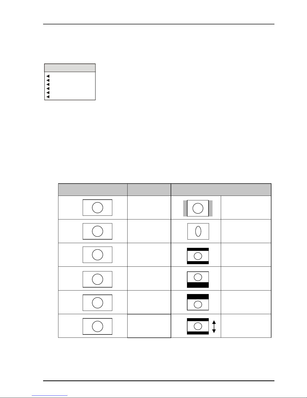
◀Letterbox Center
To maintain the correct shape of objects on the
16:9 input, this displays the 16:9 picture as a strip
across the center of the 4:3 display.
◀
◀◀
◀Anamorphic
This setting retains all picture information from the
input and passes it to fill the output image
regardless of the aspect ratio conversion. This
means that 16:9 to 4:3 conversions will appear
squeezed horizontally.
◀
◀◀
◀Center Cut-out
To maintain the correct shape of objects on the
16:9 input, this setting retains all vertical detail but
crops the left and right edges of the image.
◀
◀◀
◀Letterbox Top
To maintain the correct shape of objects on the
16:9 input, this displays the 16:9 picture as a strip
at the top of the 4:3 display.
◀
◀◀
◀Letterbox Bottom
To maintain the correct shape of objects on the
16:9 input, this displays the 16:9 picture as a strip
at the bottom of the 4:3 display.
◀
◀◀
◀L-Box Screen Saver
In this mode the picture, in letterbox format, will
slowly move up and down on the screen.
Input 16:9 Transformation Output 4:3
Center Cutout Image is side
cropped
Anamorphic Image is squeezed
horizontally
Letterbox Center
Letterbox Top
Letterbox Bottom
Letterbox Screen
Saver

IQMDA00 SECTION N1
IQMDA00OPS 090305 www.snellwilcox.com Version 1 Issue 2 N1.19
◀
◀◀
◀Patterns
This allows a pattern to chosen for the output.
CRC/EDH Reset
No
Ye s
Patterns
O/P Pattern
Pattern Type...
◀
◀◀
◀O/P Pattern
When selected the output will become the pattern
selected from the Pattern Type list.
◀
◀◀
◀Pattern Type
Pattern Type
Color Black
75% Color Bars
This allows will allow either Black or 75% Color
Bars to be used as the output signal when the O/P
Pattern item has been selected.
◀CRC/EDH
This menu provides information about the Cyclic
Redundancy Checksum errors or EDH errors
within the input.
Chroma_B/WCRC/EDH
CRC/EDH
CRC/EDH Total
CRC/EDH Reset...
◀
◀◀
◀CRC/EDH
CRC/EDH Errors
xxxxxxx
OK
CRC/EDH (Errors)
This will display the current CRC/EDH Error Rate.
◀
◀◀
◀CRC/EDH Total
CRC/EDH Total Errors
xxxxxxx
OK
CRC/EDH Total (Errors)
This will display the total CRC/EDH Error Count
since the last reset.
◀
◀◀
◀CRC/EDH Reset
CRC/EDH Reset
No
Ye s
Selecting Yes will reset the CRC/EDH error
counter to zero.
◀
◀◀
◀On I/P (Input) Loss
This controls the system response to a loss of
input signal.
Input
Black
75% Bars
On I/P Loss
◀
◀◀
◀Input
The incoming signal will be displayed whenever
possible.
◀
◀◀
◀Black
When an input loss is detected the output picture
will cut to black.
◀
◀◀
◀75% Color bars
When an input loss is detected the output picture
will become a 75% color bars pattern.
◀
◀◀
◀Audio Grp (Group) 1
One group of audio can be carried through from
the HD inputs to the SD outputs.
Audio Grp1
Audio Input Grp 1
Audio Input Grp 2
Audio Input Grp 3
Audio Input Grp 4
This item allows one of the groups to be selected.

IQMDA00 SECTION N1
IQMDA00OPS 090305 www.snellwilcox.com Version 1 Issue 2 N1.20
Memories ▶
▶▶
▶
This function allows a number of particular setups
of the IQMDA00 to be saved and recalled. There
are 16 memory locations available.
This item allows any of the 16 memory locations to
be selected.
Chroma_B/WMemories
Memory 1...
Memory 2...
Memory 3...
Memory 4...
Memory 5..
Memory 6..
Memory 7..
Memory 8...
Memory 9...
Memory 10..
Memory 11...
Memory 12...
Memory 13...
Memory 14...
Memory 15...
Memory 16...
◀
◀◀
◀Memory 1 to 16
Memory 1 to 16
Save 1-16
Name 1-16
Recall 1-16
When a memory location has been selected this
item allows it to be saved, recalled or renamed.
◀
◀◀
◀Save 1-16
When selected the current settings will be saved at
this location.
Recall 1-16 ▶
When selected the settings will be recalled from
this location and applied to the unit.
◀
◀◀
◀Name 1-16
The selected memory location may be renamed
with this function.
Name Memory 1-16
Name Memory 1-16
Clear
Preset
memory_name
OK
The ◀Clear function blanks the selected
character.
The ◀Preset function loads the default text, for
example, Memory 1.
O.K. ▶saves the memory name text and returns
to the main menu.
Table of contents
Other Snell Media Converter manuals

Snell
Snell IQMDMO User manual

Snell
Snell CVR700 User manual

Snell
Snell IQDEC0218-2A User manual

Snell
Snell IQQMD00 Operator's manual

Snell
Snell IQGBE4000-1A Operator's manual

Snell
Snell Sirius 600 User manual

Snell
Snell Kudos LC300 User manual

Snell
Snell Kudos LC300 User manual

Snell
Snell CVR800 User manual

Snell
Snell Mach HD User manual


