Snell IQDEC0218-2A User manual

IQDEC02 N24
IQDEC02OPS 23/04/09 www.snellgroup.com Version 1 Issue 7 N24.1
IQDEC02
Golden Gate Decoder, Synchronizer, Audio Embedder with
Noise Reduction and Auxiliary SDI Input – 12 bit
Table of Contents
IQDEC02 ............................................................... 1
Module Description ............................................. 2
Rear Panel View................................................... 2
Product Comparison.................................... 3
Block Diagram...................................................... 5
Features................................................................ 5
Technical Profile.................................................. 6
INPUT CONNECTIONS ........................................ 9
SERIAL IN................................................... 9
COMP IN A and B (-2 version)....................9
COMPOSITE A and B (-2A version)........... 9
COMPOSITE (-1A version)......................... 9
Separated Y C (-2 and -2A versions only)..9
ANALOG AUDIO IN .................................... 9
REFERENCE (not 15-1A version) ............ 10
GPI (-2A only)............................................10
OUTPUTS............................................................ 11
Serial Digital Video Outputs ...................... 11
AES OUT (-2 version) ............................... 11
AES OUT (-2A version)............................. 11
25 Way D Type Connection Details..........12
CARD EDGE INDICATORS................................ 14
RollCall PC Control Panel Screens.................. 15
Video ......................................................... 15
ProcAmp.................................................... 17
Decoder..................................................... 19
De-embed Pair 1-4 and 5-8....................... 21
Analog Audio Pair 1-2 ............................... 22
Mixer 1, 2, 3 and 4..................................... 23
Audio Bus A and B.................................... 24
Audio Outputs............................................25
Audio Delay Setup.....................................26
Audio Setup...............................................27
Genlock .....................................................30
VBI & HANC Blank(ing).............................32
Caption & Pattern......................................34
GPI.............................................................36
RollTrack ...................................................38
Memories...................................................40
Logging......................................................41
ROLLCALL LOG FIELDS..........................42
Setup .........................................................44
Operation from an Active Control Panel.........47
MAIN MENU..............................................51
Video .........................................................51
Decoder… .................................................55
Freeze .......................................................56
Audio .........................................................57
Genlock…..................................................63
Setup…......................................................65
Pattern.............................................65
Caption............................................66
VBI & HANC Blank(ing)...................67
GPI I/O ............................................70
RollTrack.........................................72
Logging............................................74
ROLLCALL LOG FIELDS................75
Default Output.................................77
Information Window ........................77
User Mem(ories)........................................79
IQDEC02 RollCall Commands ..........................80
RollTrack Audio Delay Tracking ......................87
Appendix 1 The Firewall ................................92
Manual Revision Record...................................94
C

IQDEC02 N24
IQDEC02OPS 23/04/09 www.snellgroup.com Version 1 Issue 7 N24.2
Module Description
The IQDEC02 provides a complete analog front-
end with 12-bit composite decoding,
synchronization and analog audio ingest in one
compact module. It is ideal for providing the bridge
between analog legacy operations and digital
environments. When paired with an upconverter
this module completes the bridge between analog
and HD domains. What makes the IQDEC02 so
powerful for these applications are its advanced 3-
D decoding algorithms employing updated
patented Golden Gate technology. These will
extract more original information from the analog
picture source than other decoders. This makes it
ideal for the transition from analog to digital or from
analog to HD. The IQDEC02 handles most
composite analog signal formats including PAL,
NTSC-M, NTSC-J, PALN, N4.43, PAL60, PALM
and SECAM. The full frame synchronizer with
horizontal and vertical phasing controls allows the
output to be timed to your house or studio
reference. In addition to its awesome video
performance, the IQDEC02 can digitize up to 4
channels of analog audio for both embedding into
the SDI stream and outputting as two AES
streams. What is more, an auxiliary SDI input is
included so that the IQDEC02 can be easily
integrated into mixed analog/digital environments.
Proc. amp controls and a powerful built-in noise
reducer complete the specification. The noise
reduction is targeted at preserving the original
content while eliminating the objectionable artifacts
of analog working. The noise reduction algorithms
are tuned to ensure optimum quality and lowest
bit-rates if the signal is subsequently compressed.
Rear Panel View
IQDEC0218-2A
AB
SERIAL IN
A
ES OUT
1
2
SERIAL OUT
IQDEC0
2/318-2A
21
COMPOSITE YC
A
NALOG AUDIO IN / AES OUT
IQDEC0216-2
COMP IN B/C
ANALOG AUDIO IN / AES OUT
12
COMP IN A/Y
SERIAL OUT
IQDEC02/316-2
SERIAL IN
IQDEC0215-1A
IQDEC0
215-1A
ANALOG AUDIO IN / AES OUT
SERIAL
OUT
1
2
COMP
IN
SERIAL IN

IQDEC02 N24
IQDEC02OPS 23/04/09 www.snellgroup.com Version 1 Issue 7 N24.3
This manual covers the following products:
IQDEC0218-2A 12 bit golden gate
decoder with synchronizer, analog audio
embedder and noise reduction. 2 composite, 1 Y/C
and 1 SDI inputs, 2 SDI outputs, 4 analog audio
inputs, 2 AES outputs (balanced, on 25D, and
unbalanced on 25D and BNC)
IQDEC0216-2 12 bit golden gate decoder with
synchronizer, analog audio embedder and noise
reduction. 2 composite, 1 Y/C and 1 SDI inputs, 2
SDI outputs, 4 analog audio inputs, 2 AES outputs
(balanced and unbalanced on 25D)
IQDEC0215-1A 12 bit golden gate decoder,
analog audio embedder with noise reduction.
single composite and SDI inputs, 2 SDI outputs, 4
analog audio inputs, 2 AES outputs (balanced and
unbalanced on 25D)
Product Comparison
Product CVBS
Inputs Y/C
Inputs SDI
Inputs Analog
Inputs AES
Outputs SDI
Outputs GPI Genlock Width &
Style
IQDEC0218-2A 2 1 1 4 BAL 2
2+2 BAL
U/B 2 1
Loop-
through Double A
IQDEC0216-2 2 1 1 4 BAL 2
2 BAL
U/B 2 1
Loop-
through Double 0
IQDEC0215-1A 1 No 1 4 BAL 2
2 BAL
U/B 2 No No Single A

IQDEC02 N24
IQDEC02OPS 23/04/09 www.snellgroup.com Version 1 Issue 7 N24.4
Note that there are two styles of rear panels available. They are not interchangeable between the two
styles of enclosures. However, the cards may be fitted into any style of enclosure.
‘A’ Style Enclosure
Rear panels with the suffix A may only be fitted
into the ‘A’ style enclosure shown below.
(Enclosure order codes IQH3A-E-0, IQH3A-E-P,
IQH3A-0-0, IQH3A-0-P)
(Enclosure order codes IQH3A-S-0, IQH3A-S-P)
(Enclosure order code IQH1A-S-P)
‘0’ Style Enclosures
Rear panels without the suffix A may only be fitted
into the ‘0’ style enclosures shown below.
setu p
lo ck save
recall
modules help
adju st
scrol l
power previous
return
home
control
information
display
select
(Enclosure order codes IQH1S-RC-0, IQH1S-RC-
AP, IQH1U-RC-0, IQH1U-RC-AP, Kudos Plus
Products)
power
OPEN
(Enclosure order codes IQH3N-0, IQH3N-P)
(Enclosure order codes IQH3U-RC-0, IQH3U-RC-P)

IQDEC02 N24
IQDEC02OPS 23/04/09 www.snellgroup.com Version 1 Issue 7 N24.5
Block
Diagram
SDI TX
Adaptive
1
2
Simple
Filter
Spatial
Comb
Filter
Minimum
Delay
Temporal
Comb
(Frame)
Filter
Additional
Filters
Noise
Reduction Horizontal
and
Vertical
Enhance
Audio
Embed
and Ancillary
Writer
SDI RX
and EQ Ancillary
Reader
Audio
De-embed Proc. Amp
Tracking
Delay
Analog
Input Stage
Analog to
Digital
Converter
Channel
Router
Proc. Amp
Proc. Amp
AES TX 1
AES TX 2
Analog
Input Stage
Analog to
Digital
Converter
Analog
Input Stage
Analog to
Digital
Converter
Analog
Input Stage
Analog to
Digital
Converter
Adjustable
Delay
Adjustable
Delay
Adjustable
Delay
network control monitoringintelligence, and
Assignable
Audio
Mixers
Assignable
Audio
Mixers
Assignable
Audio
Mixers
Assignable
Audio
Mixers
Synchronizer
Proc. Amp
Proc. Amp
Proc. Amp
Proc. Amp Proc. Amp
VHS
Decode
12-bit A-D
converter
12-bit A-D
converter
composite/Y
C
Adjustable
Delay
I/O
GPI control
and
TTL pulse I/O
Built-in
intelligence
1 X GPI
Features
•12-bit multi-standard decoder with frame
synchronizer and analog audio embedder
•Adaptive Golden Gate spatio-temporal frame
comb decoding
•Input standards – PAL*, NTSC*, NTSC-J,
N4.43, PAL60, PALN*, PALM* or SECAM*
•*Auto detection of input standards
•Minimal delay through the unit - < 7 lines (lock
to input, decoder and noise reducer in
minimum delay mode)
•Firewall for video and processed PCM audio to
provide a continuous valid output
•Motion adaptive recursive noise reducer with
automatic noise floor measurement
•Horizontal and vertical enhancer
•VHS mode: Rugged sync and clock recovery
ensures reliable operation for VHS playback
and other noisy or unstable inputs
•Y/C input (Not 15-1A), composite and SDI
inputs available
•SECAM adaptive notch and chroma median
filters
•Selectable default output on loss of input -
Frame freeze, pattern or input pass
•Selectable VBI pass through (pass flat or
blank for each VITS line)
•Adjustment of video gain, black level, chroma
gain, NTSC hue, horizontal Y/C timing and
picture position
•A total of 4 channels of embedded audio can
be processed, 2 pairs selectable from any of
the four groups
•4 x assignable 8 channel audio mixers
•Flexible audio delay features including tracking
delay to keep audio and video in perfect sync
•Full audio proc-amp including - gain, mute,
polarity invert, and channel routing
•

IQDEC02 N24
IQDEC02OPS 23/04/09 www.snellgroup.com Version 1 Issue 7 N24.6
Technical
Profile
Signal Inputs
Composite Video.................2 via BNC connectors, isolated
Y-C......................................1 via BNC connectors (Double
width versions only)
Serial Digital........................1 via BNC connectors
Analog Audio ......................4 Channels (2 Stereo Pairs) via
25D connector
Standards............................PAL/NTSC//NTSC-J/PAL-M
/PAL-N/SECAM/N4.43
Reference............................1 analog loop through via BNC
connectors (Double width versions
only)
Signal Outputs
Serial Digital........................2 x SDI via BNC connectors
AES Audio...........................2 pairs (4 channels) balanced and
unbalanced via 25D and
unbalanced via BNC connectors
(Note: Compatible with PCM
embedded audio sources only)
Standards............................SMPTE 259M-C–1997, SMPTE
272M-A-1994, AES3-1992
Control Interface
GPI/O..................................Closing contact input/output via
BNC connector (Not 15-1A)
Card Edge Controls
None
Card Edge Indicators
CPU running/Power ............Flashing = OK
Analog Video Present.........Lost = Off, Good = On (Green)
SDI Present.........................Lost = Off, Good = On (Green)
Analog Video Error .............Good = Off, Error = On (Yellow)
SDI Error ............................Good = Off, Error = On (Yellow)
Reference Present .............Lost = Off, Good = On (Green)
Reference Error .................Good = Off, Error = On (Yellow)
Functions Available via RollCall Only
Audio Controls
Line Up Tone Level.............-24 dBu to +10 dBu in 0.5 dB steps
Headroom ...........................+4 to +24 dB in 0.5 dB steps
(subject to a max input level of +24
dBu)
Set Audio Monitor Thresholds
High and low levels, time delay
External Input Audio Delay .Up to 1.5 s additional delay in 1ms
steps
Input Side Control Proc.......Independent Gain, Mute, Polarity &
Mono control over de-embedded
and analog input channels
Digital Input Gain ................±18 dB
Analog Input Gain ...............±34 dB (subject to Line up and
Headroom levels)
Channel Routing ................Output channels routed from
analog pair 1, analog pair 2, test
tone, SDI and audio mixers
Channel Mixing ...................Mixer channels routed from analog
pair 1, analog pair 2, test tone and
SDI
Output Side Control Proc....Independent Gain, Mute, Polarity &
Mono control over embedded and
AES output channels.
Digital Output Gain..............±18 dB
Global Delay Offset.............Up to +2.5 s in 1ms steps, common
to all processed audio.
Variable Audio Delay Control Source
Up to 1 s from RollTrack + GPI +
video synchronizer
Audio Level Slew Rate........Instant, fast, medium, slow
Validity Bit ...........................Clear or set
Tone Frequency, Amplitude & Ident
2-channel tone generator.
Tone Frequency..................100 Hz to 15 kHz in 100 Hz steps
Tone Channel Ident.............0.5 s interruption every 2 s
Video Controls
Input Select.........................Composite A / B, YC, SDI
Composite Input Standard ..Auto [PAL, NTSC, PALM, PALN,
SECAM] / Manual [PAL, NTSC,
NTSC-J, PALM, PALN, SECAM,
N4.43]
SDI Input Standard..............Auto / Manual [525 / 625]
Freeze.................................Off / On
Luma Gain...........................±6 dB
Chroma Gain.......................±6 dB
Black Level..........................±120 mV
NTSC Hue...........................±45°
Y/C Timing .........................+592 ns in 148 ns steps
Picture Position...................±592 ns in 148 ns steps

IQDEC02 N24
IQDEC02OPS 23/04/09 www.snellgroup.com Version 1 Issue 7 N24.7
Blanking ..............................Left, right, top, bottom, color
Noise Reducer Mode & Noise Measurement
Auto / Manual noise measurement
Normal / Minimum delay
Noise Threshold..................Auto Bias [±7] / Manual [0 to 15]
Noise Reducer Strength......Luma [0 to 31], Chroma [0 to 31]
H Enhance ..........................Off / [On – low, medium, high]
H Enhance Frequency ........2.25 MHz or 3.375 MHz
V Enhance...........................Off / [On – low, medium, high]
Decoder Mode ....................Simple, Studio, VHS/Unstable
SECAM Notch.....................Adaptive/Controllable
SECAM Luma Bandwidth ...Wide/Medium/Narrow
SECAM Bottles ...................Auto/On/Off
Color Killer...........................Chroma ON / Chroma OFF / Auto
[QAM standards: Chroma off =
chroma mute + Y notch
SECAM: Chroma off = chroma
mute only]
Genlock H Phase................± ½line in 1 pixel steps
Genlock V Phase ................±262/312 lines in 1 line steps
Genlock Mode.....................Free-run / Lock to reference / Lock
to input (minimum delay)
H Delay ...............................1 line in 1 pixel steps
V Delay................................524/624 lines in 1 line steps
Additional Video Delay........0, 1 or 2 frames of delay
NTSC lines 11 to 20 and 274 to 282
Blank, pass as VBI, decode VBI
NTSC line 22, 283 and 285 Blank, pass as data, pass as
picture
NTSC line 21 and 284 Blank, pass as data, pass as
picture, pass as closed captions
PAL lines 7 to22 & 320 to 335
Blank, pass as VBI, decode VBI
PAL line 23 Blank, pass as WSS, pass as
picture
Horizontal Ancillary Blank ...Off / On
Other Controls
Pattern Enable ....................Off / On
Pattern Select......................Black / EBU Color Bars / 100%
Color Bars / Ramp / Multi-Burst /
Pulse & Bar / Animated Bar
Caption Enable ..................Off / On
Caption Generator...............Programmable up to 19 characters
GPI Action...........................Memories 1 to 8 / Pattern / Freeze /
Audio delay
GPI Polarity.........................High / Low
GPO Action.........................Input loss / Standard / Video delay
GPO Polarity.......................High / Low
User Memories....................Name, clear, save and recall 8 user
memories
Default Video Output...........Pass Video / Freeze / Pattern /
Pattern and Caption
Default Audio Output...........Silence
Preset Unit ..........................Returns all settings to default
Reporting * also Logged
Input Status ........................*Input present, *Input line standard,
*Composite color standard
Input Error...........................One or more inputs have
unselected line standard
Reference Status ................*Ref present, *Ref standard
Reference Error...................Standard different to selected input
EDH.....................................*Presence / *Error-Minute / *Error-
Hour
Input Ancillary Error.............Bad checksums, invalid formatting
of HANC
Embedded Audio Status .....*Input audio pair present, *Input
audio pair non-PCM
Audio Bus Monitor...............*Silence, *High Level, *Low Level,
*Overflow for processed audio
channels
Analog Audio Input Monitor.*Silence, *High Level, *Low Level,
*Overflow for analog audio input
channels
RollTrack Input
Delay...................................Audio delay – Fixed, RollTrack +
Fixed, Internal Sync + Fixed
RollTrack Output
Delay...................................Current video / audio delay
Input State...........................Present / line standard
Reference State..................Present / error
Embedded Audio Status .....Input audio pair present

IQDEC02 N24
IQDEC02OPS 23/04/09 www.snellgroup.com Version 1 Issue 7 N24.8
Specifications
Video Specifications
Video Internal Processing...4:2:2 with 10 bit data paths
Frequency Response (Studio Mode)
Y..........................................5.75 MHz ±0.1dB
PbPr....................................1.5 MHz -3dB
Frequency Response (VHS Mode)
Y..........................................5 MHz +0.2 dB, -0.5 dB
PbPr....................................1.5MHz -3dB typ
Composite Input Return Loss
Better than 35 dB to 5 MHz
Composite level/impedance1 V pk-pk typ. Into 75 Ohm
Serial Input Return Loss .....Better than 15 dB from 100 kHz to
270 MHz
Maximum Serial Input Cable Length
> 200 m (PSF1/2 or equiv. cable)
Serial Output Level .............800 mV ±5%
Output Overshoot................< 70 mV
Output Return Loss.............Better than 15 dB to 270 MHz
Output Jitter.........................< 0.2 UI (with 10 Hz High pass filter
selected on 601 monitor)
Reference Return Loss.......Better than 35 dB to 5.8 MHz
Reference Input Level.........1 Vp-p ± 3 dB
Sync Level...........................0.3 V ± 6 dB into 10k Ohms
Delay through the unit
Decoder Delay ....................<2 lines (Line Comb)
<1 frame + 1 line (Frame Comb)
Synchronizer Delay.............16 µs (Lock to Input)
1 frame + 16 µs (Lock to
Reference)
Additional Processing Delay<100 µs
Noise Reducer Delay..........<1 frame (Normal)
<3 lines (Minimum Delay)
Total Minimum Delay ..........<7 lines
Total Maximum Delay ........>5 frames (including optional video
delay)
Audio Specifications
Input Impedance .................>30 K Ohms, balanced, line to line
>15 K Ohms line to earth (600 Ohm
link selectable)
Max Input Level...................+24 dBu, balanced
Frequency Response..........+0.1/-0.25 dB, 20 Hz – 20 kHz wrt
1 kHz
THD+N................................<-94 dB typical at –1 dBFS, 1 kHz,
22 Hz - 20 kHz, 'A' weighted, unity
gain
Sampling.............................24 bits @ 48 kHz,
Dynamic Range...................>100 dB wrt –1 dBFS, 20 Hz to 20
kHz, ‘A’ weighted
CMMR.................................>50 dB typical at 60 Hz
Cross Talk...........................< -100 dB, 20-20 kHz, +24 dBu,
channel to channel
Channel Gain Mismatch......< ±0.2 dB
Max Output Level................0 dBFS
Output Sampling .................48 kHz
Power Consumption
Module Power Consumption13 W
Technical Profile (continued)

IQDEC02 N24
IQDEC02OPS 23/04/09 www.snellgroup.com Version 1 Issue 7 N24.9
INPUT CONNECTIONS
SERIAL IN
The serial digital input is made to the unit via a
BNC connector which terminates in 75 Ohms.
COMP IN A and B (-2 version)
These are the two composite video inputs to the
module via BNC connectors. Nominal input level is
1 V p-p terminated in 75 Ohms.
COMPOSITE A and B (-2A version)
These are the two composite video inputs to the
module via BNC connectors. Nominal input level is
1 V p-p terminated in 75 Ohms.
COMPOSITE (-1A version)
This is the composite video input to the module via
a BNC connector. Nominal input level is 1 V p-p
terminated in 75 Ohms.
Separated Y C (-2 and -2A versions only)
A Y-C (S-VHS, Hi-8 etc.) input signal may be
connected to the unit via two BNC connectors
marked Y and C.
Y input level is a nominal 1V p-p into 75 Ohms.
C input is nominal color burst level into 75 Ohms.
ANALOG AUDIO IN
Four balanced analog inputs are made to the unit
via a 25 way D Type connector.
For connection details please see pages 11 & 12.
The input Impedance is >30 k Ohms (line to line).
This may be changed to 600 Ohms using the
on-board link as shown below.
These Links should be
left in the position shown
>30k Ohms Position
600 Ohms Position
Audio Input Terminator
Link Settings
High Impedance
75 Ohm Termination
Reference Input
Terminator Link Setting
SERIAL IN
SERIAL IN
AB
COMPOSITE
Y
C
COMP
IN
COMP IN B/C
COMP IN A/Y
SERIAL IN
A
NALOG AUDIO IN / AES OUT
A
NALOG AUDIO IN / AES OUT
IQDEC02/31

IQDEC02 N24
IQDEC02OPS 23/04/09 www.snellgroup.com Version 1 Issue 7 N24.10
REFERENCE (not 15-1A version)
The analog reference input to the unit is made via
the passive loop-through BNC connectors for 75
Ohms.
The signal may be black burst or composite video
at standard levels.
Note that if the loop-through facility is not used the
unused BNC socket must be fitted with a 75 Ohm
terminator or the Reference Input Termination link
on the card set to the 75 ohm position as shown
below.
These Links should be
left in the position shown
>30k Ohms Position
600 Ohms Position
Audio Input Terminator
Link Settings
High Impedance
75 Ohm Termination
Reference Input
Terminator Link Setting
GPI (-2A only)
This connector is used for accepting GPI
information (from mechanical switch contacts,
relay contacts etc.) The resulting action that the
unit takes may be programmed via RollCall.
It may also be configured as an output.
GPI Signal
Return
+5V
GPI Port
as an input
B
COMPOSITE
C
IQDEC0
2/318-2A
GPI Signal
Return
+5V
GPI Port
as an output
+VDD

IQDEC02 N24
IQDEC02OPS 23/04/09 www.snellgroup.com Version 1 Issue 7 N24.11
OUTPUTS
Serial Digital Video Outputs
These are the two Serial Digital outputs of the unit
via BNC connectors for 75 Ohms.
AES OUT (-2 version)
Balanced and unbalanced AES outputs are
available via the 25 way D type connector.
For connection details please see pages 12 & 13.
AES OUT (-2A version)
Balanced and unbalanced AES outputs are
available via the 25 way D type connector; two
unbalanced AES outputs are also available via
BNC connectors for 75 Ohms.
For connection details please see pages 12 & 13.
SERIAL OUT
21
12
SERIAL OUT
1
6-2
A
NALOG AUDIO IN / AES OUT
IQDEC02/31
A
NALOG AUDIO IN / AES OUT
AES OUT
1
2

IQDEC02 N24
IQDEC02OPS 23/04/09 www.snellgroup.com Version 1 Issue 7 N24.12
25 Way D Type Connection Details
By Pin Number
Pin No Description Connection
1 Chassis Ground Ground
2 Channel 1 + Analog Audio In 1L +
3 Channel 2 + Analog Audio In 1R +
4 Ground (2) Ground
5 Channel 3 + Analog Audio In 2L +
6 Channel 4 + Analog Audio In 2R +
7 Ground (4) Ground
8 Channel 5 + AES 1 Out (Unbalanced) +
9 Channel 6 + AES 1 Out (Balanced) +
10 Ground (6) Ground
11 Channel 7 + AES 2 Out (Balanced) +
12 Channel 8 + AES 2 Out (Unbalanced) +
13 Ground (8) Ground
14 Ground (1) Ground
15 Channel 1 – Analog Audio In 1L –
16 Channel 2 – Analog Audio In 1R –
17 Ground (3) Ground
18 Channel 3 – Analog Audio In 2L –
19 Channel 4 – Analog Audio In 2R –
20 Ground (5) Ground
21 Channel 5 – AES1 Out (Unbalanced) –
22 Channel 6 – AES 1 Out (Balanced) –
23 Ground (7) Ground
24 Channel 7 – AES2 Out (Balanced) –
25 Channel 8 – AES2 Out (Unbalanced) –
By Function
Pin No Description Connection
1 Chassis Ground Ground
2 Channel 1 + Analog Audio In 1L +
15 Channel 1 – Analog Audio In 1L –
14 Ground (1) Ground
3 Channel 2 + Analog Audio In 1R +
16 Channel 2 – Analog Audio In 1R –
4 Ground (2) Ground
5 Channel 3 + Analog Audio In 2L +
18 Channel 3 – Analog Audio In 2L –
17 Ground (3) Ground
6 Channel 4 + Analog Audio In 2R +
19 Channel 4 – Analog Audio In 2R –
7 Ground (4) Ground
8 Channel 5 + AES 1 Out (Unbalanced) +
21 Channel 5 – AES1 Out (Unbalanced) –
20 Ground (5) Ground
9 Channel 6 + AES 1 Out (Balanced) +
22 Channel 6 – AES 1 Out (Balanced) –
10 Ground (6) Ground
11 Channel 7 + AES 2 Out (Balanced) +
24 Channel 7 – AES2 Out (Balanced) –
23 Ground (7) Ground
12 Channel 8 + AES 2 Out (Unbalanced) +
25 Channel 8 – AES2 Out (Unbalanced) –
13 Ground (8) Ground

IQDEC02 N24
IQDEC02OPS 23/04/09 www.snellgroup.com Version 1 Issue 7 N24.13
Example of Connection to XLR Connectors
25 Way
Male D-Type
XLR
Connections
Solder
Pin
S
i
de
16
19
22
25
2
5
8
11
1
3
4
6
7
9
10
12
13
14
15
17
18
20
21
23
24
XLR
Connections
Analog Audio
Input 1 Right
Analog Audio
Input 1 Right 2
AES Output 1
(balanced)
AES Output 2
(unbalanced)
Analog Audio
Input 1 Left
Analog Audio
Input 2 Left
AES Output 1
(unbalanced)
AES Output 2
(balanced)
IQDEC02 N24
IQDEC02OPS 23/04/09 www.snellgroup.com Version 1 Issue 7 N24.14
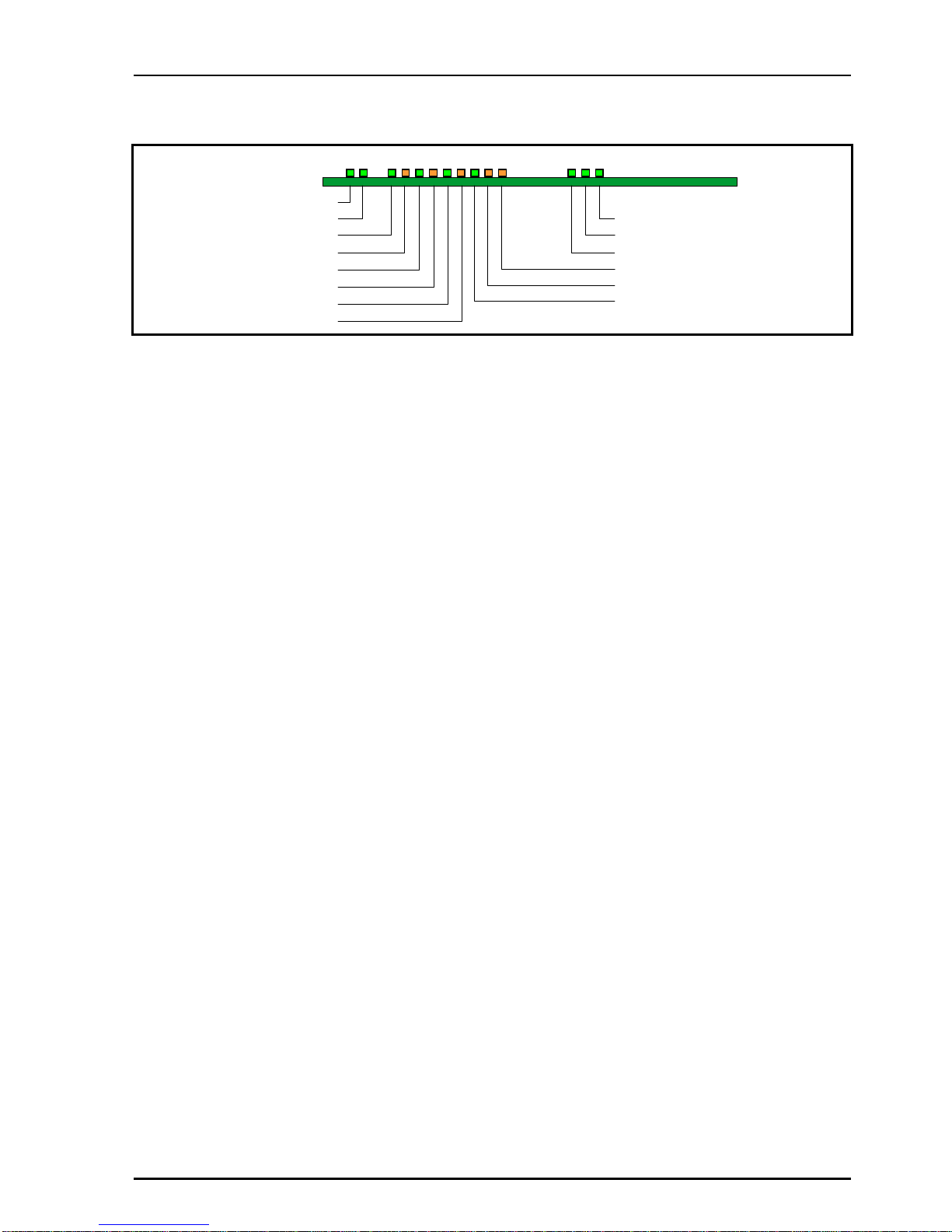
CARD EDGE INDICATORS
D1 D2 D3 D4 D5 D6 D7 D8 D9 D10 D11 D16 D17 D18
Synchronizer FPGA OK
Decoder FPGA OK
CPU OK (flashing)
EDH Error in the Last Hour
EDH Error in the Last Minute
EDH Present
-PWR
-PWR
A
nalog Video Present
Analog Video Error
SDI Present
SDI Error
Reference Present
Reference Error
LED INDICATORS
D1: -PWR (Green)
When illuminated this indicates that the negative
power supply is operating.
D2: +PWR (Green)
When illuminated this indicates that the positive
power supply is operating.
D3: Analog Video Present (Green)
When illuminated this indicates that there is a valid
signal at the composite input.
D4: Analog Video Error (Amber)
When illuminated this indicates that there is an
invalid signal at the composite input.
D5: SDI Present (Green)
When illuminated this indicates that there is a valid
signal at the SDI input.
D6: SDI Error (Amber)
When illuminated this indicates that the SDI input
is not at the current operating standard.
D7: Reference Present (Green)
When illuminated this will indicate that a valid
reference signal is present.
D8: Reference Error (Amber)
When illuminated this will indicate that an invalid
reference signal is present.
D9: EDH Present (Green)
When illuminated this indicates that there is EDH
present on the SDI signal.
D10: EDH Error in the Last Minute (Amber)
When illuminated this indicates that there has
been an EDH Error in the Last minute.
D11: EDH Error in the Last Hour (Amber)
When illuminated this indicates that there has
been an EDH Error in the Last Hour.
D16: CPU OK (flashing) (Green)
This LED will flash to indicate that the CPU is
running.
D17: Decoder FPGA OK (Green)
This will illuminate when the Decoder FPGA has
been loaded.
D18: Synchronizer FPGA OK (Green)
This will illuminate when the Decoder FPGA has
been loaded.

IQDEC02 N24
IQDEC02OPS 23/04/09 www.snellgroup.com Version 1 Issue 7 N24.15
RollCall PC Control Panel Screens
Video
Select
This allows either the Composite A, Composite
B, YC or SDI input to be selected for processing.
Note that if the unit is de-embedding audio from an
SDI signal and then a composite or YC signal is
selected the unit will continue to de-embed and
output the audio from the SDI signal.
Input SDI Standard
This allows input standard for the SDI input to be
selected.
If only 625 is selected the unit will be forced to only
accept 625 line inputs.
If only 525 is selected the unit will be forced to only
accept 525 line inputs.
If 625 and 525 are selected the unit will accept
both 625 and 525 line inputs.
Composite/YC Color Standard
This allows the automatic detection of the color
standard(s) for the composite/YC input.
The module will automatically detect any of the
color standards that have been checked.
In the screen example above the unit will
automatically detect PAL, NTSC, PAL-M, PAL-N,
N4.43 60 and SECAM but will not detect NTSC-J
or PAL4.43 60.
Note that when selecting and deselecting SECAM
the output picture and audio may suffer some
disruption.
Freeze
When checked the output picture will become a
frozen frame.

IQDEC02 N24
IQDEC02OPS 23/04/09 www.snellgroup.com Version 1 Issue 7 N24.16
Video (continued)
Noise Reducer
This allows settings and adjustments to be made
to the noise reducer.
Delay Mode
This allows the delay of the noise reducer to be
selected.
Normal
In this mode the delay will be < 1 Frame
Minimum
This mode produces the minimum input/output
delay and may be used where audio delay
problems may exist and cannot be compensated
for. In this mode the delay will be < 3 Lines
Manual/Auto
Manual
In this mode the noise floor may be adjusted
manually using the Manual Noise Threshold
control.
Noise Measured
This provides an indication of how much noise
there is in the signal. A clean signal will give low
figures and a noisy signal high figures.
Auto
In this mode the noise floor is automatically
measured and the threshold is adjusted
dynamically set to an appropriate value for the
current input noise level. The noise detection
algorithm may be given a subjective bias using the
Auto Threshold Bias control to give more or less
noise reduction. Modification of the bias should not
be necessary under normal circumstances.
Luma Strength
This control changes the amount of noise
reduction for the luminance by limiting the
maximum level of noise reduction, where 31 is
maximum and 0 is minimum. Preset is to 0. The
actual level of noise reduction is dynamically
adjusted on a pixel-by-pixel basis with regard to
the noise reduction setting for the same pixel in the
previous frame.
Chroma Strength
This control changes the amount of noise
reduction for the chrominance by limiting the
maximum level of noise reduction, where 31 is
maximum and 0 is minimum. Preset is to 0. The
actual level of noise reduction is dynamically
adjusted on a pixel-by-pixel basis with regard to
the noise reduction setting for the same pixel in the
previous frame.
Manual Selected

IQDEC02 N24
IQDEC02OPS 23/04/09 www.snellgroup.com Version 1 Issue 7 N24.17
ProcAmp
These items allow various signal parameters to be
adjusted.
Note that for this and other screens the following
applies to the scroll bars:
The and symbols at the ends of the scroll
bar allow the value to be adjusted in discrete
steps.
The numerical value will be shown above the scroll
bars and selecting Preset will return the
setting to the calibrated value for that item.
Luma Gain
This allows the Y (luminance) gain to be adjusted
by ±6 dB in steps of 0.1 dB. Preset value is 0.0 dB.
Note that the maximum input level is +3 dB.
Black Level
This allows the black level to be adjusted by +120
mV in 0.5mV steps. Preset value is 0.
Chroma Gain
This allows the U/V (color difference) gain to be
adjusted by ±6 dB in steps of 0.1 dB. Preset value
is 0.0 dB.
Note that the maximum input level is +3 dB.
NTSC Hue
This item allows the Hue of an NTSC signal to be
adjusted.
The range of adjustment is ±45 degrees. Preset is
to 0 degrees.
Picture Position
This item allows the timing of the picture position
relative to the normal value, to be adjusted.
The timing may be adjusted by +592ns in 148ns
steps. Preset value is 0.
Y/C Timing
This item allows the timing of the chrominance
signal relative to the luminance signal to be
adjusted, (i.e. Y to Cb/Cr timing) in nanoseconds.
The timing may be adjusted by +592ns in 148ns
steps. Preset value is 0.

IQDEC02 N24
IQDEC02OPS 23/04/09 www.snellgroup.com Version 1 Issue 7 N24.18
ProcAmp (continued)
Blanking
This allows the active picture to be blanked out or
cropped on each of the four sides.
Left/Right
The range of adjustment is from 0 to 200 pixels in
steps of 2 pixels. Preset is to 0 pixels.
Top/Bottom
The range of adjustment is from 0 to 200 lines.
Preset is to 0 lines.
The color of the blanked area may be set using the
Red, Blue and Green controls. The range of
adjustment is from 0 to 255 units. Preset is to 0, 0,
0 units (Black).
Enhance
This allows Vertical and Horizontal enhancement
to be applied to the picture.
V Enhance
This allows vertical enhancement to be applied to
the processed signal.
The level of enhancement may set to 0 (Off), 1
(Low), 2 (Medium) and 3 (High). Preset is to 0.
H Enhance
This allows Horizontal enhancement to be applied
to the processed signal. The non-linear process
prevents enhancement of low amplitude signals
typical of noise.
The level of enhancement may set to 0 (Off), 1
(Low), 2 (Medium) and 3 (High). Preset is to 0.
H Enhance Frequency
The frequency at which the horizontal
enhancement is applied may be set to either
3.375 MHz or 2.250 MHz. Preset is to 3.375 MHz.

IQDEC02 N24
IQDEC02OPS 23/04/09 www.snellgroup.com Version 1 Issue 7 N24.19
Decoder
This screen allows the decoder functions to be set
up.
Decoder
This allows the type of decoding to selected.
Studio
▶This mode uses enhanced Golden Gate
technology. The composite input is sampled with
12-bit resolution and decoded using adaptive line
and frame comb filters to ensure optimum
decoding performance.
▶
Simple
This simple decode mode incorporates a wide
bandwidth subcarrier notch filter. This mode is for
reference only and should not be used for normal
composite material.
VHS/Unstable
In this mode the decoder will cope with sources
with unstable time-bases but the decoding is of a
lower quality and the frequency response is
reduced.
Note that in this mode the decoder will
automatically be set to Minimum Delay operation.
Color Killer
This function controls the color content of the
picture.
Chroma Off
When selected the color content of the picture will
be removed. The luma signal is produced using a
narrow bandwidth notch filter.
Chroma On
When selected the color content of the picture will be
maintained regardless of the level of the color burst.
Auto
When this item is enabled the picture will become
monochrome if the input color burst disappears or
the level drops below a critical amplitude. The
picture will return to color when the burst level
reappears.
Minimum Delay
This mode produces the minimum input/output
delay and may be used where audio delay
problems may exist and cannot be compensated
for. It uses the same adaption technique as the
Studio mode but has asymmetric frame stores.

IQDEC02 N24
IQDEC02OPS 23/04/09 www.snellgroup.com Version 1 Issue 7 N24.20
Decoder (continued)
SECAM Studio
This function allows adjustments to decoding
parameters for a SECAM signal of studio (stable)
quality.
Notch
Either the Adaptive or the Controllable luminance
notch filter may be enabled with this item.
Luma Bandwidth
This function allows the bandwidth of the decoded
luminance to be adjusted.
Wide The signal will be processed at full
bandwidth (3.4 MHz).
Medium The signal will be processed with a
bandwidth of approximately 2.6 MHz.
Narrow The signal will be processed with a
bandwidth of approximately 1.7 MHz.
SECAM VHS
This function allows adjustments to decoding
parameters for a SECAM signal of VHS (unstable)
quality.
Luma Bandwidth
This function allows the bandwidth of the decoded
luminance to be adjusted.
Wide The signal will be processed at full
bandwidth (3.4 MHz).
Medium The signal will be processed with a
bandwidth of approximately 2.6 MHz.
Narrow The signal will be processed with a
bandwidth of approximately 1.7 MHz.
This manual suits for next models
2
Table of contents
Other Snell Media Converter manuals

Snell
Snell IQQMD00 Operator's manual

Snell
Snell IQMDA00 User manual

Snell
Snell CVR800 User manual

Snell
Snell IQGBE4000-1A Operator's manual

Snell
Snell IQMDMO User manual

Snell
Snell Mach HD Operator's manual

Snell
Snell Kudos LC300 User manual

Snell
Snell CVR700 User manual

Snell
Snell Mach HD User manual

Snell
Snell Sirius 600 User manual


