Snell IQQMD00 Operator's manual

snellgroup.com
User Instruction Manual
IQQMD00
Quad-link-SDI Down Converter for Ultra HD Signals

IQQMD00 www.snellgroup.com Contents
Issue 1 Rev 1 Page 2 © 2015 Snell Limited
Contents
1. About this Manual . . . . . . . . . . . . . . . . . . . . . . . . . . . . . . . . . . . . . . . . . . . . . . . . . . . . . . 4
1.1 Contact Details . . . . . . . . . . . . . . . . . . . . . . . . . . . . . . . . . . . . . . . . . . . . . . . . . . . . . . 4
1.2 Copyright and Disclaimer . . . . . . . . . . . . . . . . . . . . . . . . . . . . . . . . . . . . . . . . . . . . . . 4
2. Introduction. . . . . . . . . . . . . . . . . . . . . . . . . . . . . . . . . . . . . . . . . . . . . . . . . . . . . . . . . . . . 5
2.1 Order Codes . . . . . . . . . . . . . . . . . . . . . . . . . . . . . . . . . . . . . . . . . . . . . . . . . . . . . . . . 6
2.2 Fiber SFP Options. . . . . . . . . . . . . . . . . . . . . . . . . . . . . . . . . . . . . . . . . . . . . . . . . . . . 6
2.3 Rear Panel View . . . . . . . . . . . . . . . . . . . . . . . . . . . . . . . . . . . . . . . . . . . . . . . . . . . . . 6
2.3.1 IQQMD0000-1A3, IQQMD0000-1B3 . . . . . . . . . . . . . . . . . . . . . . . . . . . . . . . 6
2.4 Enclosures. . . . . . . . . . . . . . . . . . . . . . . . . . . . . . . . . . . . . . . . . . . . . . . . . . . . . . . . . . 7
2.5 Feature Summary . . . . . . . . . . . . . . . . . . . . . . . . . . . . . . . . . . . . . . . . . . . . . . . . . . . . 8
3. Technical Specification . . . . . . . . . . . . . . . . . . . . . . . . . . . . . . . . . . . . . . . . . . . . . . . . . . 9
3.1 Inputs and Outputs . . . . . . . . . . . . . . . . . . . . . . . . . . . . . . . . . . . . . . . . . . . . . . . . . . . 9
3.2 Indicators. . . . . . . . . . . . . . . . . . . . . . . . . . . . . . . . . . . . . . . . . . . . . . . . . . . . . . . . . . . 9
3.3 RollCall Features. . . . . . . . . . . . . . . . . . . . . . . . . . . . . . . . . . . . . . . . . . . . . . . . . . . . 10
3.4 Specifications . . . . . . . . . . . . . . . . . . . . . . . . . . . . . . . . . . . . . . . . . . . . . . . . . . . . . . .11
4. Connections . . . . . . . . . . . . . . . . . . . . . . . . . . . . . . . . . . . . . . . . . . . . . . . . . . . . . . . . . . 12
4.1 SDI Inputs . . . . . . . . . . . . . . . . . . . . . . . . . . . . . . . . . . . . . . . . . . . . . . . . . . . . . . . . . 12
4.2 SDI Output. . . . . . . . . . . . . . . . . . . . . . . . . . . . . . . . . . . . . . . . . . . . . . . . . . . . . . . . . 12
4.3 GPIO . . . . . . . . . . . . . . . . . . . . . . . . . . . . . . . . . . . . . . . . . . . . . . . . . . . . . . . . . . . . . 12
4.4 SFP . . . . . . . . . . . . . . . . . . . . . . . . . . . . . . . . . . . . . . . . . . . . . . . . . . . . . . . . . . . . . . 12
5. Card Edge LEDs . . . . . . . . . . . . . . . . . . . . . . . . . . . . . . . . . . . . . . . . . . . . . . . . . . . . . . . 13
6. RollCall Control Panel . . . . . . . . . . . . . . . . . . . . . . . . . . . . . . . . . . . . . . . . . . . . . . . . . . 15
6.1 Information Window. . . . . . . . . . . . . . . . . . . . . . . . . . . . . . . . . . . . . . . . . . . . . . . . . . 15
6.1.1 Video Input / Output Summary. . . . . . . . . . . . . . . . . . . . . . . . . . . . . . . . . . . 15
6.1.2 Video Input Status . . . . . . . . . . . . . . . . . . . . . . . . . . . . . . . . . . . . . . . . . . . . 16
6.1.3 Video Output Status . . . . . . . . . . . . . . . . . . . . . . . . . . . . . . . . . . . . . . . . . . . 16
6.2 Video. . . . . . . . . . . . . . . . . . . . . . . . . . . . . . . . . . . . . . . . . . . . . . . . . . . . . . . . . . . . . 17
6.2.1 Inputs . . . . . . . . . . . . . . . . . . . . . . . . . . . . . . . . . . . . . . . . . . . . . . . . . . . . . . 17
6.2.2 Outputs. . . . . . . . . . . . . . . . . . . . . . . . . . . . . . . . . . . . . . . . . . . . . . . . . . . . . 18
6.2.3 References. . . . . . . . . . . . . . . . . . . . . . . . . . . . . . . . . . . . . . . . . . . . . . . . . . 18
6.3 System GPIO . . . . . . . . . . . . . . . . . . . . . . . . . . . . . . . . . . . . . . . . . . . . . . . . . . . . . . 20
6.3.1 GPIO 1, 2, 3, 4, 5 & 6. . . . . . . . . . . . . . . . . . . . . . . . . . . . . . . . . . . . . . . . . . 20
6.3.2 GPI. . . . . . . . . . . . . . . . . . . . . . . . . . . . . . . . . . . . . . . . . . . . . . . . . . . . . . . . 21
6.3.3 GPO . . . . . . . . . . . . . . . . . . . . . . . . . . . . . . . . . . . . . . . . . . . . . . . . . . . . . . . 22
6.4 Memories. . . . . . . . . . . . . . . . . . . . . . . . . . . . . . . . . . . . . . . . . . . . . . . . . . . . . . . . . . 23
6.4.1 Saving Memory Settings . . . . . . . . . . . . . . . . . . . . . . . . . . . . . . . . . . . . . . . 23
6.4.2 Changing a Memory Name . . . . . . . . . . . . . . . . . . . . . . . . . . . . . . . . . . . . . 23
6.4.3 Recalling a Memory . . . . . . . . . . . . . . . . . . . . . . . . . . . . . . . . . . . . . . . . . . . 23
6.5 Savesets . . . . . . . . . . . . . . . . . . . . . . . . . . . . . . . . . . . . . . . . . . . . . . . . . . . . . . . . . . 24
6.5.1 Saving a saveset . . . . . . . . . . . . . . . . . . . . . . . . . . . . . . . . . . . . . . . . . . . . . 24
6.5.2 Restoring a saveset . . . . . . . . . . . . . . . . . . . . . . . . . . . . . . . . . . . . . . . . . . . 24
6.6 Logging . . . . . . . . . . . . . . . . . . . . . . . . . . . . . . . . . . . . . . . . . . . . . . . . . . . . . . . . . . . 25
6.6.1 Logging - Video . . . . . . . . . . . . . . . . . . . . . . . . . . . . . . . . . . . . . . . . . . . . . . 25
6.6.2 Logging - System . . . . . . . . . . . . . . . . . . . . . . . . . . . . . . . . . . . . . . . . . . . . . 26
6.6.3 Logging Misc . . . . . . . . . . . . . . . . . . . . . . . . . . . . . . . . . . . . . . . . . . . . . . . . 27

IQQMD00 www.snellgroup.com Contents
Issue 1 Rev 1 Page 3 © 2015 Snell Limited
6.7 RollTrack . . . . . . . . . . . . . . . . . . . . . . . . . . . . . . . . . . . . . . . . . . . . . . . . . . . . . . . . . . 28
6.7.1 Disable All . . . . . . . . . . . . . . . . . . . . . . . . . . . . . . . . . . . . . . . . . . . . . . . . . . 28
6.7.2 RollTrack Index . . . . . . . . . . . . . . . . . . . . . . . . . . . . . . . . . . . . . . . . . . . . . . 28
6.7.3 RollTrack Source . . . . . . . . . . . . . . . . . . . . . . . . . . . . . . . . . . . . . . . . . . . . . 28
6.7.4 RollTrack Address . . . . . . . . . . . . . . . . . . . . . . . . . . . . . . . . . . . . . . . . . . . . 29
6.7.5 RollTrack Command. . . . . . . . . . . . . . . . . . . . . . . . . . . . . . . . . . . . . . . . . . . 29
6.7.6 RollTrack Sending . . . . . . . . . . . . . . . . . . . . . . . . . . . . . . . . . . . . . . . . . . . . 29
6.7.7 RollTrack Status. . . . . . . . . . . . . . . . . . . . . . . . . . . . . . . . . . . . . . . . . . . . . . 30
6.8 Setup. . . . . . . . . . . . . . . . . . . . . . . . . . . . . . . . . . . . . . . . . . . . . . . . . . . . . . . . . . . . . 31
6.8.1 Factory Settings . . . . . . . . . . . . . . . . . . . . . . . . . . . . . . . . . . . . . . . . . . . . . . 31
6.8.2 Default Settings . . . . . . . . . . . . . . . . . . . . . . . . . . . . . . . . . . . . . . . . . . . . . . 31
6.8.3 Restart . . . . . . . . . . . . . . . . . . . . . . . . . . . . . . . . . . . . . . . . . . . . . . . . . . . . . 31

IQQMD00 www.snellgroup.com About this Manual
Issue 1 Rev 1 Page 4 © 2015 Snell Limited
1. About this Manual
This manual describes the IQQMD00 Quad-link-SDI Down Converter for Ultra HD Signals.
If you have any questions regarding the installation and setup of your product, please refer to
the Customer Service contact details (see section 1.1).
1.1 Contact Details
For details of our Regional Customer Support Offices please visit the Snell website and
navigate to Support/Customer Support Contacts.
www.snellgroup.com/support/customer-support
Customers with a support contract should call their personalized number, which can be found
in their contract, and be ready to provide their contract number and details.
1.2 Copyright and Disclaimer
Copyright protection claimed includes all forms and matters of copyrightable material and
information now allowed by statutory or judicial law or hereinafter granted, including without
limitation, material generated from the software programs which are displayed on the screen
such as icons, screen display looks etc.
Information in this manual and software are subject to change without notice and does not
represent a commitment on the part of Snell Limited. The software described in this manual is
furnished under a license agreement and may not be reproduced or copied in any manner
without prior agreement with Snell Limited or their authorized agents.
Reproduction or disassembly of embedded computer programs or algorithms prohibited.
No part of this publication may be transmitted or reproduced in any form or by any means,
electronic or mechanical, including photocopy, recording or any information storage and
retrieval system, without permission being granted, in writing, by the publishers or their
authorized agents.
Snell operates a policy of continuous improvement and development. Snell reserves the right
to make changes and improvements to any of the products described in this document
without prior notice.
IQQMD00 www.snellgroup.com Introduction
Issue 1 Rev 1 Page 5 © 2015 Snell Limited
2. Introduction
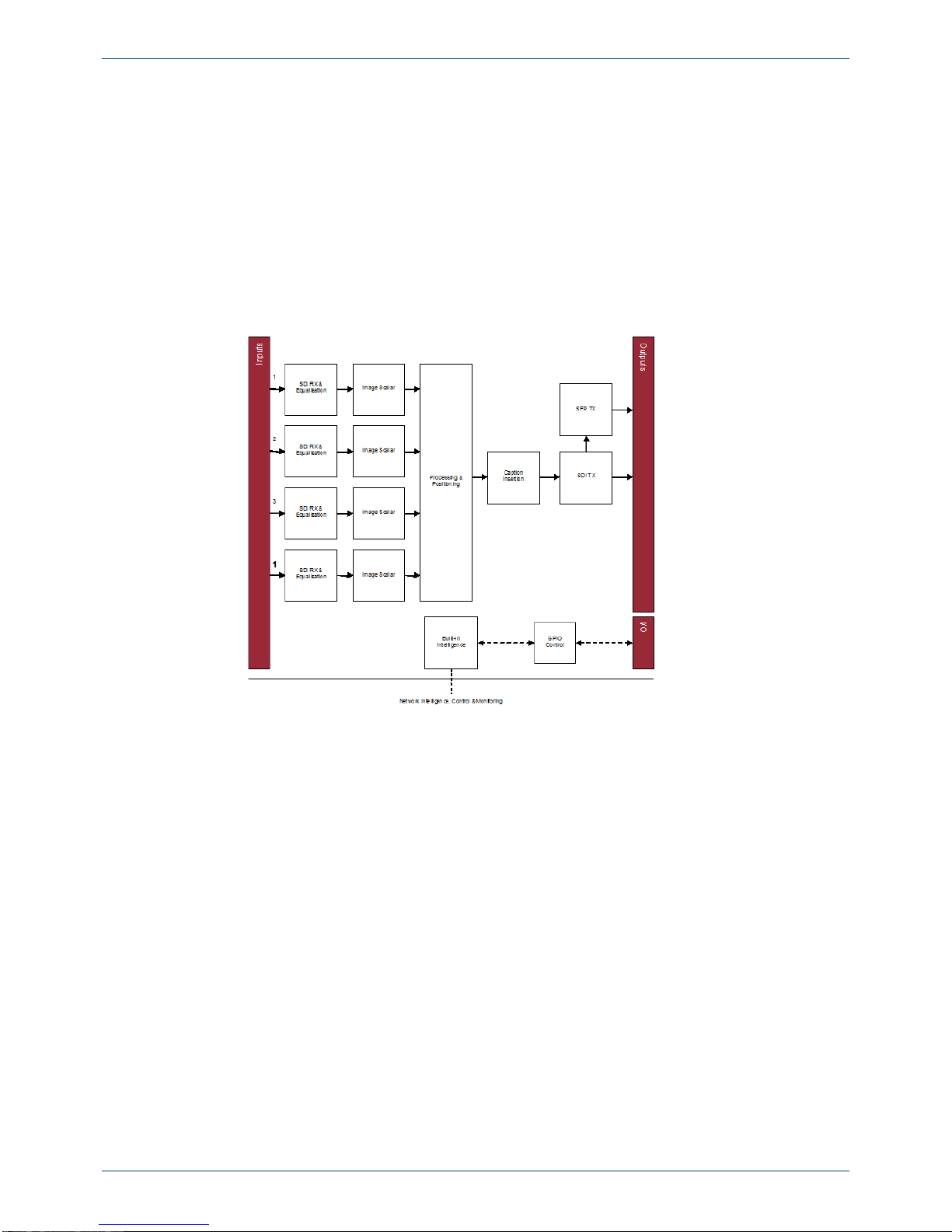
The IQQMD00 provides conversion for Quad-link Ultra HD SDI inputs to SDI outputs in
1080p, 1080i, 720p or SD formats. This allows Ultra High Definition signals to be integrated
into existing HD/SD-SDI workflows and monitored on standard 1920 x 1080 displays
removing the need for expensive Ultra HD specific equipment and monitors.
Drawing on Snell's extensive experience in conversion technology the IQQMD00 uses high
quality scaling and filtering technology to down convert and align the quad-link input to
provide a clean and sharp HD/SD output, ideal for monitoring and other signal distribution
applications.
The video output from this module is SDI with an option to add fiber, copper or HDMI SFP
module to extend the output capabilities of the IQQMD00.
Fig 1. Block diagram
IQQMD00 www.snellgroup.com Introduction
Issue 1 Rev 1 Page 6 © 2015 Snell Limited
2.1 Order Codes
The following order codes are available.
2.2 Fiber SFP Options
Order codes for the SFP options:
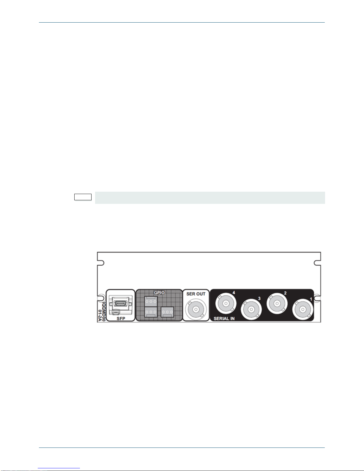
2.3 Rear Panel View
This section contains the available rear panels.
2.3.1 IQQMD0000-1A3, IQQMD0000-1B3
IQQMD0000-2B3 3G/HD/SD-SDI Quad-link Monitoring downconverter. 4 SDI inputs, 1
SDI output, up to 2 SFP outputs, 6 GPIs.
IQQMD0001-2A3 3G/HD/SD-SDI Quad-link Monitoring downconverter. 4 SDI inputs, 1
SDI output, up to 2 SFP outputs, 6 GPIs.
FC1-13T1 Single 1310nm fiber Tx
FC1-13T2 Dual 1310nm fiber Tx
FC1-15T1 Single 1550nm fiber Tx
FC1-15T2 Dual 1550nm fiber Tx
FC1-HDBT2 HD-BNC Dual Tx
FC1-HDMI2 HDMI Tx with 2m cable
Fiber CWDM Tx Wavelengths available on request
Note:
Fiber SFP type must be ordered in addition to the module.
Fig 2. IQQMD0000-1A3, IQQMD0000-1B3
IQQMD00 www.snellgroup.com Introduction
Issue 1 Rev 1 Page 7 © 2015 Snell Limited
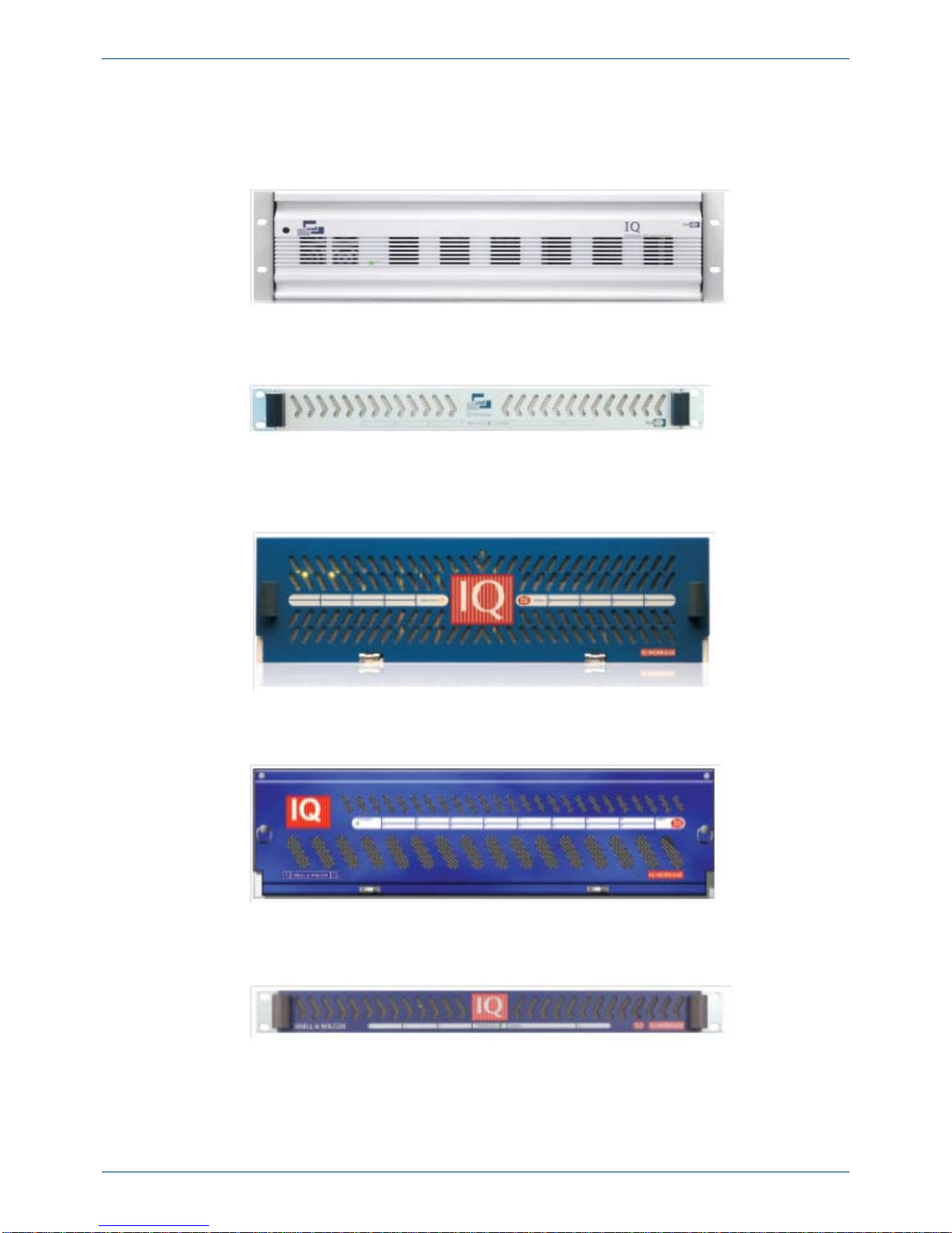
2.4 Enclosures
IQQMD00 can only be fitted in the following enclosures, shown below:
IQH3B-S-0, IQH3B-S-P
IQH1A-S-P
IQH3A-S-0, IQH3A-S-P
IQH3A-E-0, IQH3A-E-P, IQH3A-0-P
IQH1A-S-P
Fig 3. IQH3B-S-0, IQH3B-S-P
Fig 4. IQH1A-S-P
Fig 5. IQH3A-S-0, IQH1A-S-P
Fig 6. IQH3A-E-0, IQH3A-E-P, IGH3A-0-P
Fig 7. IQH1A-S-P

IQQMD00 www.snellgroup.com Introduction
Issue 1 Rev 1 Page 8 © 2015 Snell Limited
2.5 Feature Summary
The IQQMD00 Quad-link-SDI Down Converter for Ultra HD Signals provides the following
features:
• Custom scaling and filtering to provide seamless reconstruction of a quad-link
• UHD input for HD single link applications
• Standards supported:
• 3G-SDI to SMPTE 424M/425M level A compatible
• HD-SDI to SMPTE292M/274M/296M
• SD-SDI to SMPTE259M-C
• 4K-UHD Quad Link to both Quadrant based and SMPTE 2036 pixel interleave
• SFP cage enables output over HDMI, fiber or additional SDI via HD-BNC
• User definable caption generator for image identification
• 16 x user memories, save/recall/rename
• Rollcall control and monitoring compatible
• Input loss detection with default captions

IQQMD00 www.snellgroup.com Technical Specification
Issue 1 Rev 1 Page 9 © 2015 Snell Limited
3. Technical Specification
This section contains technical information for the IQQMD00 module.
3.1 Inputs and Outputs
3.2 Indicators
Inputs and
Outputs
Signal Inputs
Inputs 4
Connector/Format BNC / 75 Ohm panel jack on standard Snell connector panel
Input Cable Length Up to 100m Belden 1694A @ 3Gbps
Return loss >-10 dB 1.5GHz to 3GHz
Signal Outputs
Outputs 1 x BNC & 1 x SFP monitor out dual transmitter capable
Electrical 3G/HD/SD-SDI
Connector/Format BNC / 75 Ohm
Standards SMPTE 424M (3G level A)
SMPTE 292M (HD)
SMPTE 259M-C (SD)
Control Interface
GPI 6 (I/O configurable)
Electrical TTL-compatible, active-low driven
Connector/Format Molex connection
Table 1 Inputs and Outputs
Indicators Front Panel & Card Edge
V+ OK (Green)
V- OK (Green)
CPU OK (Green flashing)
Input Status No input status (Red)
3G Input Standard Present (Blue)
Frame Reference Not Available (Off)
No input (Red)
HD input (Green)
SD input (Yellow)
Error OK (Off)
Booting, until SDI enabled (Red)
Running, Board Fault (Red)
Warn OK (Off or blinking yellow)
Operational Error Warning (Yellow continuous)
Good OK (Green)
Table 2 Indicators - Front Panel & Card Edge

IQQMD00 www.snellgroup.com Technical Specification
Issue 1 Rev 1 Page 10 © 2015 Snell Limited
3.3 RollCall Features
RollCall Features
SDI Input Status Name, Status, Presence and Standard
SDI Output Status Standard, Status, SFP
Reference Status State, Source and Standard
GPIO Status State
SDI Input Control Input Name
Sony/SMPTE
Video Output
Control SDI Output Standard
Reference control Source: Input 1-4, Reference A-B
GPIO Control Direction: Unused, Input, Output
Invert
GPI Input High Action
GPI Input Low Action
GPO Output Source
User memories Name, save and recall 16 user memories
Information Window Video Input/Output Summary
Video Input Status
Video Output Status
Factory Defaults Resets all of the unit's settings to their factory defaults
Default Settings Resets all of the unit's settings to their factory defaults without clearing
the User memories
Video Logging Input Name
Input State
Input Standard
Output Monitor Type
Output Standard
Output SFP Status
Genlock State
Reference State
Reference Standard
Reference Source
Reference Type
Frame Reference State
Frame Reference Standard
System Logging FPGA Temperature
Misc Logging Version Numbers
Uptime
Rear ID
Rear Status
Slot Width
Slot Start
Power usage
Module IDs
Licensed Options
RollTrack Controls On/off, Index, Source, Address, Command, Status, Sending
Table 3 RollCall Features

IQQMD00 www.snellgroup.com Technical Specification
Issue 1 Rev 1 Page 11 © 2015 Snell Limited
3.4 Specifications
Specifications
Conversion Delay 2 input frames
Start-up Time 28 seconds
Power
consumption
Module Power
Consumption 22.5W/20.5PR
Table 4 Specifications

IQQMD00 www.snellgroup.com Connections
Issue 1 Rev 1 Page 12 © 2015 Snell Limited
4. Connections
This section contains information on the module connectors.
4.1 SDI Inputs
4.2 SDI Output
4.3 GPIO
4.4 SFP
Fig 8. SDI Output
Fig 9. SDI Input
Fig 10. GPIO
Fig 11. SFP

IQQMD00 www.snellgroup.com Card Edge LEDs
Issue 1 Rev 1 Page 13 © 2015 Snell Limited
5. Card Edge LEDs
The LEDs on the edge of the module indicate its operating status.
LED Color Description
CH1
CH2
CH3
CH4
No Input Present (Red)
3G Present (Blue)
HD Present (Green)
SD Present (Yellow)
SDI input 1 to 4 respectively. These
LEDs are illuminated when a valid
input is present at the Serial Data
Inputs.
CH5-CH8 Not used
REF1
REF2 Not Available (Off)
No Input (Red)
HD Input (Green)
SD Input (Yellow)
Frame References 1 and 2
respectively. These LEDs indicate that
a reference signal is present.
The module must be mounted in a B-style frame and one or more frame reference signal
must be connected to use frame references.
V+ OK (Green) Indicates that the respective power
supply is present.
V- OK (Green) Indicates that the respective power
supply is present.
CPU OK (Green) Flashes to indicate that the CPU is
working/active.
Table 5 Card Edge LEDs
Fig 12. Card Edge LEDs

IQQMD00 www.snellgroup.com Card Edge LEDs
Issue 1 Rev 1 Page 14 © 2015 Snell Limited
ERR OK (Off)
Board Fault (Red) This LED indicates board fault
conditions.
When the unit is booting, this LED is
illuminated until the SDI is enabled.
Board fault errors include:
• Serializer lock fault. Output
serializer fails to lock.
• SDI JTAG board fault. Internal
JTAG interface is inadvertently
enabled.
Continuous illumination indicates a
board fault and a service is required.
Perform a Factory Reset and supply a
valid SDI video source before calling
service.
WARN OK (Off or Blinking Yellow)
Operational Error Warning
(Yellow Continuous)
This LED indicates operational errors.
Operational errors include:
• InputVideo-Incompatible input
standard - Detected input stan-
dard is invalid.
• Input Video: SDI problem -
CRC or other SDI errors
detected on selected input in
the last whole field.
• Reference: Lock Failure - Gen-
lock failed to lock to selected
source.
This LED is briefly illuminated in
transitional states like standard
changes.
GOOD OK (Green) Indicates that the module is operating
correctly.
LED Color Description
Table 5 Card Edge LEDs
IQQMD00 www.snellgroup.com RollCall Control Panel
Issue 1 Rev 1 Page 15 © 2015 Snell Limited
6. RollCall Control Panel
This section contains information on using the IQQMDOO module with RollCall.
6.1 Information Window
The Information Window appears in the upper-right corner of each screen and enables you
to select the basic information (Input or Output) to display in the Information pane. The
Information pane displays the status of video inputs and outputs.
6.1.1 Video Input / Output Summary
Selecting this option on the Information Window pane displays the following video Inputs,
Output and Reference information on the Information pane as shown below:
The following information is available:
Fig 13. Video input and output status
Name Status Description
IN1
IN2
IN3
IN4
LOST
1080/50p
1080/59p
No status present
OUT 525/29i, 625/25i, 1080/29i,
1080/25i, 720/59p, 720/50p,
1080/59pA, 1080/50pA
Selected output standard.
Post fixed with an A to indicate
Level-A.
REF OK
FAIL If the Reference is OK, displays
state OK and the Standard (for
example, 1080/59pA) of the
reference
Table 6 Video input and output summary
Fig 14. Video input and output summary

IQQMD00 www.snellgroup.com RollCall Control Panel
Issue 1 Rev 1 Page 16 © 2015 Snell Limited
6.1.2 Video Input Status
Selecting this option on the Information Window pane displays the following video Inputs,
Output and Reference information on the Information pane as shown below:
The following information is available:
6.1.3 Video Output Status
Selecting this option on the Information Window pane displays the following video Inputs,
Output and Reference information on the Information pane as shown below:
The following information is available:
Name Status Description
IN1
IN2
IN3
IN4
LOST
1080/50A OK
1080/59A OK
No input present
Detected standard of input signal.
Valid input signal received
Table 7 Video input status
Fig 15. Video input status
Name Status Description
OUT 525/29i, 625/25i, 1080/29i,
1080/25i, 720/59p,
720/50p, 1080/59pA,
1080/50pA
Selected output standard
Post fixed with an A to indicate
Level-A
GEN WARN:FreeRun Selected reference source or
freerun (No Reference Lock)
REF OK
FAIL
No reference present or OK_(Ref
standard)
Table 8 Video output status
Fig 16. Video output status

IQQMD00 www.snellgroup.com RollCall Control Panel
Issue 1 Rev 1 Page 17 © 2015 Snell Limited
6.2 Video
The Video pane enables you to specify and view the settings and status for all the video
inputs, video output, monitor output and reference.
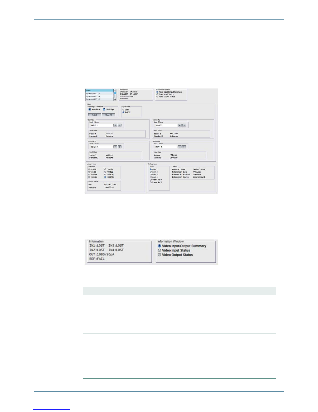
6.2.1 Inputs
The following information is provided:
Fig 17. Video
Name Description
Valid Input Standards The Valid Input Formats check boxes specify the video input
standards that the module will accept. The module will
automatically detect the standard of the received input and
indicate any signal that does not comply with the selected video
formats as INVALID.
Input Mode Selects either Sony or SMPTE pixel interleave standard for the
4K-UHD input signal.
In Sony mode, the inputs are discreet 4k images and are
displayed one per quadrant. Normally, each input would be ¼ of
the image and would combine to be a single picture. If you
emulate it by providing 4 ordinary 4k pictures, they appear 1 per
quadrant.
In SMPTE mode, each input is pixel multiplexed so if you present
the same ordinary 4k signal into each input, it always appears as
a single picture.
Table 9 Inputs
Fig 18. Inputs

IQQMD00 www.snellgroup.com RollCall Control Panel
Issue 1 Rev 1 Page 18 © 2015 Snell Limited
6.2.2 Outputs
The following information is provided:
6.2.3 References
The following options enable you to control and monitor the reference inputs:
Input Caption Enable Only available for the Sony standard.
These are the input names displayed in Logging Inputs and
presented on the output as UMD captions along with the inputs
video image.
To change the name of Input 1 or Input 2, type the name in the
text field and click S. To return the name to its factory default, click
P.
Input State Displays the status and video standard of the input.
Name Description
Table 9 Inputs
Name Description
Standard Select the required SDI output video standard.
Output status Displays the status and video standard of the video outputs.
Table 10 Outputs
Fig 19. Outputs
Fig 20. References

IQQMD00 www.snellgroup.com RollCall Control Panel
Issue 1 Rev 1 Page 19 © 2015 Snell Limited
Name Description
Select Select the required reference standard.
Status Displays the status and video standard of the video outputs as follows:
•Genlock 1 State - WARN:Freerun or OK:Input / OK:Reference
•Reference 1 State - FAIL:Lost or OK
•Reference 1 Standard - Unknown / 525/29i / 625/25i / 1080/29i /
1080/25i / 720/59p / 720/50p / 1080/59pA / 1080/50pA
•Reference 1 Source - Lock to Input 1 / Lock to Input 2 / Lock to Input
3 / Lock to Input 4 / Frame Ref A / Frame Ref B
Table 11 References

IQQMD00 www.snellgroup.com RollCall Control Panel
Issue 1 Rev 1 Page 20 © 2015 Snell Limited
6.3 System GPIO
The GPIO controls are used to configure the six General Purpose Input / Output (GPIO)
connector functionality.
6.3.1 GPIO 1, 2, 3, 4, 5 & 6
The following options enable you to control and monitor the GPIOs.
Fig 21. System GPIO
Name Description
GPIO The options are:
•Unused - When the GPIO is inactive
•Input - Configures the GPI as an input. This enables you to choose
what action occurs when the GPI input receives a driven state High
(>2Volts) or Low (<0.8Volts)
•Output - Configures the GPI as an output. This enables you to choose
what trigger occurs to produce an output signal at the GPI connector
when the GPI output is driven Low (+0.5V typical) or, if the Invert func-
tion is selected, Driving the GPI output High (+5V typical)
Status Displays the GPIO status.
Invert Configure the GPI to be active low when it is an Output.
Table 12 GPIO configuration
Fig 22. GPIO 1-2
Table of contents
Other Snell Media Converter manuals

Snell
Snell Kudos LC300 User manual

Snell
Snell Sirius 600 User manual

Snell
Snell Kudos LC300 User manual

Snell
Snell CVR800 User manual

Snell
Snell IQGBE4000-1A Operator's manual

Snell
Snell Mach HD User manual

Snell
Snell CVR700 User manual

Snell
Snell IQDEC0218-2A User manual

Snell
Snell IQMDA00 User manual

Snell
Snell Mach HD Operator's manual


