Snell ES-103 Guide

AS-23-33 2019.06
1
Semi‐auto strapping machine
Operatingmanualandsparepartslist
ES‐103/ES‐104/
ES‐104C/ES‐104L
ES-103 ES-104
ES-104C ES-104L

AS-23-33 2019.06
2
Table of contents
1. General..................................................... 3
2. Technical data..........................................4
Control elements......................................5
Operating .................................................6
Maintenance.............................................7
Troubleshooting.......................................8
3. Electrical diagram....................................11
4. Adjustments .............................................13
Spare parts list
Control unit....................................................15
Frame unit (ES-103) ...................................... 19
Frame unit (ES-104) ......................................21
Frame unit (ES-104C)....................................29
Frame unit (ES-104L)....................................31
Reel unit (ES-103) .........................................35
Reel unit (ES-104) .........................................37
Electric control unit .......................................41

AS-23-33 2019.06
3
General
Description
The light and compact des0ign allows easy transportation and op-
eration in a very small space.
A single motor powers these models assuring stable operation
even if the voltage drops.
Strap widths to 6-15.5 mm can be easily adjusted by loosening
only two screws. Different strap guides are available to allow use
of 6-15.5 mm strap widths.
The cams, feeding and tensioning systems are designed to elimi-
nate strap splitting, bending and scratching.
The narrow sealing head allows strapping of irregular and cylin-
drical goods.
Automatic re-feeding of the strap. The operator needs only to
place the strap around the goods and insert into the slot. No train-
ing is required.
These models require only the most basic maintenance. Electrical
and mechanical components are designed for easy replacement.
Safety rules
ELECTRIC SHOCK
MECHANISM HAZARDOUS
HIGH TEMPERATURE
It is prohibited for unauthorized persons to use the machine!
Observe all safety precautions and warnings signs.
Do not remove or override any safeguards.
Do not clean the machine or try to affect repairs while it is in operationmain switch to off!
Do not touch the welding element tongue if the machine has been switched on (operating tempera-
ture exceeds 280C).
After performing adjustment, machine sure to reinstall the cover panels.
In case of fire it is strictly prohibited to use water for the extinction.
Never put any heavy article on power cord which could cause fire or electric shock.
Follow the instructions provided in this manual.
Attention:
Before removing any enclosures for maintenance or service always pull out the power plug.

AS-23-33 2019.06
4
Semi-automatic strapping machine
Capacity:
approx.12 strapping/minute
Min. package size:
60 x 30 mm
Max. package size:
any size
Strap tension:
150 - 450 N
Strap width:
(6, 9), 12 and 15.5 mm
Strap dispenser:
Inside diameter of coil
200 , 230 and 280 mm
Perceived noise level:
approx. 70dBA
Power consumption:
approx. 0,77kW
Power connection:
110V/60Hz/1Ph
230V/50Hz/1Ph
Dimensions:
see drawing
Technical data

AS-23-33 2019.06
5
Control elements
Main switch
“1” Power ON.
“0” Power OFF
Length knob
The length of the strap be fed out can be pre-set automatically by adjusting the knob.
Reset push button switch
Aggregate start a cycle.
Feed push button switch
To feed strap out of machine freely.
Power plug
To be connected to a power source.
1. Strap dispenser
A roll of strap is mounted here.
2. Brake arm
Prevent over-ration of the strap reel
3. Strap guide for brake
The strap is threaded through this guide
4. Idle strap guide
The strap is passed through this guide
5. Strap insertion inlet
The free end of the strap should be inserted here to initiate the tensioning and cutting cycle.

AS-23-33 2019.06
6
Operating
Turn the timer knob to determine the length of strapping supplied for next cycle. Timer graduations
are provided from 0 to 5 seconds. The length of strap fed out in one second is approx. 1 meter.
Place a package on the top of the machine, and pass the free end around the package; insert the
leading end of the strapping into the strapping inlet until the leading end is detected.
Weld cooling time
Weld cooling time adjustable; the cooling delay time can be adjusted from 0~1.2 sets, delay time
will be longer by turning VR clockwise.
Tightening of strapping starts as soon as the strap is detected and the heat sealing process automati-
cally takes place after completion of tightening. After these processes have been completed, a preset
length of the strapping is dispensed automatically. This is one complete cycle.
After cycle is completed, motor will turn off automatically if strapping cycle is not initiated within
30 seconds.
Attention:
Be sure to turn off the main power switch after operation is completed for the day.

AS-23-33 2019.06
7
Maintenance
1. General
Keep the machine clean and neat at all times
The sealer housing assembly should be blown out weekly.
Attention:
Pullout the plug before removing any enclosures for mainte-
nance or service.
2. Lubrication
Apply a few drops of light lubricant (Daphne Mechanic oil or equivalent) to oil holes and on sliding
parts (see the diagram above) once per week.
Change the oil of the gearbox once per year. 150 ml of Daphne oil or its equivalent should be used.
3. Replacing the fuse
Remove the top plate of the machine and the fuse
from the fuse box located near relays. Replace the
faulty fuse with new one.
Be sure that the machine is disconnected from the
power source when checking and replacing fuses.

AS-23-33 2019.06
8
Troubleshooting
1. The strap will not feed out
1. Turn the motor switch OFF.
2. Strongly pull the strap out in the tightening direction.
2. Strap is buckled and jammed
Remedy:
1. Remove hexagon nut (1), spring washer (2) and flat washer (3).
2. Remove set screw M4 (4).
3. Remove feed roller shaft (5). Remove front-end adjusts plate.
4. Lift the front of shaft holder (6) by about 24 mm.
Pull out the jammed strap and cut it off below the buckled section. Clean the whole section.
Re-assemble in the following order 2,1,3.
3.Strap is jammed between the roller and the guide
Remedy:
1. Remove hexagon nut (1), spring washer (2) and flat washer (3).
2. Remove set screw M4 (4).
3. Remove shaft holder.
Attention:
1. You should never touch the hexagon nut (9) (painted in red). Re-assemble by reversing the disas-
sembly instructions.
2. Do not over tighten the hexagon nut which should allow the holder arm (10) move up and down
smoothly. The clearance between flat washer (3) and hexagon nut (1) should be about 0.5mm.

AS-23-33 2019.06
9
Troubleshooting
1. The gripper is locked in the raised position
Remedy:
1. Turn the motor switch OFF, then turn it on again
2. If this does not work, adjust the switch level below the slide for LS1, so that activation and
disactivation of LS1 is correct.
2. The roller is wedged against the guide
Remedy:
Remove shaft holder, loosen and set screw for fixing the guide (11), and then refix the guide with a
clearance of 0.1- 0.2 mm
3. Bad sealing
Remedy:
In most cases of poor heat-sealing, the heater temperature is either too low or too high. Make the ap-
propriate adjustment.
4. Low heater temperature
The strap shows no trace of having been melted and is easily pealed off. Lower the heater tempera-
ture by adjusting the control knob on the heater transformer.
5. High heater temperature
The strap is deformed, curled or poorly aligned and not sealed.

AS-23-33 2019.06
10
Troubleshooting
6. Strap will not reverse for tensioning
Remedy:
The Strap is in the correct position, but sealing doe
not take place, which occurs when a soft article
(package) is being loosely strapped and the friction
plate in the tightening adjustment section is slipping.
1. Turn off the motor switch, wait until the motor
completely stops and turn the switch on again.
2. You may slightly turn the tightening adjustment
nut A in the clockwise direction to increase the
tension.
The same problem may also occur when there is oil on the tightening roller causing the strap to slip.
Keep the roller clean and free of oil.

AS-23-33 2019.06
11
Electrical diagram
─
Main circuit

AS-23-33 2019.06
12
Electrical diagram
─
Connecting diagram

AS-23-33 2019.06
13
Adjustments
1. Strap width
Adjustment for straps of different width (x) can be done with a Philips screwdriver.
The two strap guides have to be adjusted so there is a clearance between strap and guide of 0.5 mm
to 1.0 mm.
Make both adjustments by loosening two screws and moving the guide to fit the strap, which is to be
used.
2. Strap tension
The adjustments are made with two adjustment nuts, the tightening adjustment nut A and the strap
pressing adjustment nut B.
Adjustment nut B does not require adjustment.
Both nuts are turned clockwise to increase the tension and counter clockwise to decrease it.
Attention:
Adjustment nut B is fixed by a lock nut (2).

AS-23-33 2019.06
14
SparepartslistES‐103/ES‐104/
ES‐104C/ES‐104L

AS-23-33 2019.06
15
Control unit
80
86
85
101
104
135
135
142
144
83
82 134
81
138
84
103
143
142
143
142
115
108
105
109
110
109
102
100
87
134
92
73
106
107
135
135
97
8
7
99
89
90
95
91
93
39
145
134
42
44
123
124
43
29
107
109
110
109
116
111
112
113
64
125
70A
73
135
70
71
136
72
60
61
59
58
57
135
58
63 62
132
142
119
142
121
107
143
118
142
109
110
109
117
122
25
26
27
28
146
152
147
148
149150
151
17
18
19
20
21
22
23
24
152
16
78
76
135
74
135
79
142
142
75
77
55
56
30
127
32
33
134
33
35
145
36
31
37
38
49
53
50
134
49A
54
34
48A
134
50
48
53
54
34
134
50
47A
53
47
54
34
129
128
9
130
11
12 4
131
40
41
45
10
46
51
ES103006-0
88
153
154
155
156
155
4A

AS-23-33 2019.06
16
Control unit
No Part No Description Qty
4 S23-191002 Pulley 1
4A S23-191000I Reducer Box Assembly 1
7 S13-110008 O-Ring 1
8 S13-110009 Solenoid Shaft 1
9 S23-190011 Motor Pulley 1
10 S35-125011 Rear End Guide 1
11 S23-191001 Reduction Gear Box 1
12 E21-020004 Clutch 1
16 S23-190003-1 Cam Shaft 1
17 S23-180011 Colla
r
1
18 S23-180012 Colla
r
1
19 S23-180013 Colla
r
1
20 S23-180014 Colla
r
1
21 S23-180015 Colla
r
1
22 S23-180016 Colla
r
1
23 S23-180017 Colla
r
1
24 S23-180018 Colla
r
1
25 S13-121201-1
R
ear Grip Ca
m
1
26 S13-121202 Heater Ca
m
1
27 S23-190016 Press Grip Ca
m
1
28 S13-121204-1 Front Grip Ca
m
1
29 S23-190006 Heater Holde
r
1
30 S13-122001 Slide Table 1
31 S13-122002 Separator Ar
m
1
32 S13-122003 Pin 1
33 S13-122005 Colla
r
2
34 S13-122006 Spring #71 3
35 S13-122007 Gu
m
1
36 S13-122008 Spring Hoo
k
1
37 S35-122012-CSP Switch Leve
r
1
38 S35-122150-1 Separato
r
1
39 S23-190004-1 Plate 1
40 S35-125008 Strap Guide Adjustment Plate 1
41 S35-125009 Strap Guide Fixed Plate 1
42 S23-190019-0 Spring 1
43 S23-190005-2 Heater Plate 1
44 S23-190150 Heater Arm Assembly 1
45 S13-123002 Cutter Holde
r
1
46 S13-123003 Clamp Bar Guide Li
d
1
47 S13-130004 Rear Clamp Ba
r
1
47A S13-130004A Rear Clamp Bar Set 1
48 S13-123201 Press Ba
r
1
48A S13-123200N Press Bar Set 1
49 S13-123101-1 Front Clam
p
Ba
r
1
49A S13-123100N Front Clam
p
Bar Set 1
50 S13-123103 Plun
g
e
r
3
51 S13-123008 S
p
rin
g
Hoo
k
1

AS-23-33 2019.06
17
Control unit
No Part No Description Qty
53 S13-123102 Plunger Spring 3
54 S13-123105 Spring Hoo
k
3
55 S13-125002 Base Guide (A) 1
56 S13-125003 Base Guide (B) 1
57 S13-160001-02 Pulley #170 1
58 S13-160002 Friction Disc. 2
59 S13-160003N Clutch Plate ( R ) 1
60 S13-160004 Spring 1
61 S13-160006 Spring Retaine
r
1
62 S13-160007-2 Round Belt 1
63 S13-160009N Clutch Plate (L) 1
64 S23-160012-3 Fixed Arm for Open Type 1
70 S13-161101 Rotating Tube 1
70A S13-161100 Adjusting Tube Assembly 1
71 S13-161102 Fixed Tube 1
72 S13-161005 Spring Retaine
r
1
73 S13-161006 Washe
r
2
74 S13-162001 Pulley Bracket 1
75 S13-162002 Hinge Bracket 1
76 S13-162003-1 Counter Shaft #137 1
77 S13-162004 Hinge Pin 1
78 S23-190012 Pulley 2
79 S23-190010 Pulley 1
80 S13-163001 Bracket 1
81 S13-163003 Pulley #139 1
82 S13-163004 Pulley #210 1
83 S13-163005 Pin #152 1
84 S13-163006 Shaft #144 1
85 S13-163013 Collar #215 1
86 S13-163050 Arm #146 1
87 S13-164001 Feed Back Ar
m
1
88 S13-164002 Stopper Bracket 1
89 S13-164003 Adjustment Nut 1
90 S13-164004 Spring #130 1
91 S13-164005 Spring #187 1
92 S13-164006 Spring #186 1
93 S13-164007 Spring #183 1
95 S13-164009 Spring Retainer #130-1 1
97 S13-164012 Pull Shaft 1
99 P08-213006 Label (Tension) 1
100 S13-164015 Feed Back Arm Pin 1
101 S13-170001-01 Pin #221 1
102 S13-171001-01 Roller Bracket 1
103 S13-171003N-01 Feed Roller Shaft 1
104 S13-171004N Roller Shaft 1
105 S13-171007-2 Pin #209 1

AS-23-33 2019.06
18
Control unit
No Part No Description Qty
106 S13-171008N Feed Back Gear 1
107 S13-171009N Gear 3
108 S13-171012 Roller #192 1
109 S13-171017 Collar (A) 8
110 S13-171019-02 Roller #116 4
111 S13-171021-01 Outlet Cover #215 1
112 S13-171022 Band Adjustment Plate 1
113 S13-171023-01 Outlet Guide #216 1
115 S13-171026-01 Inlet Cover #212 1
116 S13-171031 Washer #213 1
117 S13-172002-01 Shaft Holder 1
118 S13-172005N Feed Roller Shaft 1
119 S13-172006N Roller Shaft 1
121 S13-172014-01 Gear 1
122 S13-164011-01 Washer #223 1
123 S13-172029 Front End Guide 1
124 S13-172030 Front End Adjustment Plate 1
125 S13-160011-1 Fixed Arm For Close Type 1
127 S35-125001 Cam Bracket 1
128 S35-125005 Bearing Cover 1
129 S35-125006 Bearing Cover 1
130 G16-010027 V-Belt, M-27 1
131 G16-070019 V-Belt, K-19 1
132 G16-070021 V-Belt, K-21 1
134 G04-210635 Bearing, 635ZZ 7
135 G04-216002 Bearing, 6002ZZ 12
136 G04-216005 Bearing, 6005ZZ 1
138 G04-210608 Bearing, 608ZZ 1
142 W35-050515 Parallel Key (5*5*15) 8
143 W35-050520 Parallel Key (5*5*20) 3
144 W35-050538 Parallel Key (5*5*38) 1
145 S13-122009 Slide Table Spring 2
146 S13-121205 Separator Cam 1
147 S13-121206 Feed Back Cam 1
148 S23-190017 LS3/LS4 Cam 1
149 S23-180019 Fixed Collar 1
150 W19-010106 Pain Washer PW M6 1
151 W01-510620 Soc.hd Cap Screw HBS M6×20 1
152 G04-216003 Bearing 6003ZZ 1
153 S35-125010 Limit Switch Bracket 1
154 S35-125004 Switch Pin 1
155 S35-215001-1 Heater Cover 1

AS-23-33 2019.06
19
Frame unit─ES-103

AS-23-33 2019.06
20
Frame unit─ES-103
No Part No Description Qty
201 S23-190009-1 Bracket 1
202 S13-300009 Knob 2
204 S13-350002-0 Support 1
205 S23-330050R2 Top Plate (Hinge Type) 1
206 S13-300008R2 Package Guide 1
208 S13-300016 Plastic Lid 1
209 S13-390050R1 Support Rod 1
224 S23-330001-2 Screw 1
235 S13-423001 Shaft 1
237 S13-171026-3 Inlet Cover (15mm) 1
240 S13-370050-2 Frame 1
S13-370650-0 Frame(CE) 1
241 S13-330050R1 Side Door (L) 1
242 S14-300001R1-4 Protection Cover 1
243 S13-340050R1 Side Door (R) 1
244 S13-300010 Plastic Lid 2
246 S13-330053 Bead 1
247 S13-423150 Band Guide Bracket 1
248 S23-424001 Roller 1
249 S23-300011 Caster 4
250 S13-300013 Lock Pin 1
251 S13-312150 Reel Bracket (R) 1
253 S13-440002 Support Pad (R) 1
254 S13-430002 Support Pad (L) 1
This manual suits for next models
3
Table of contents
Popular Packaging Equipment manuals by other brands
AirSaver
AirSaver F2 Safety instructions, setup & installation manual
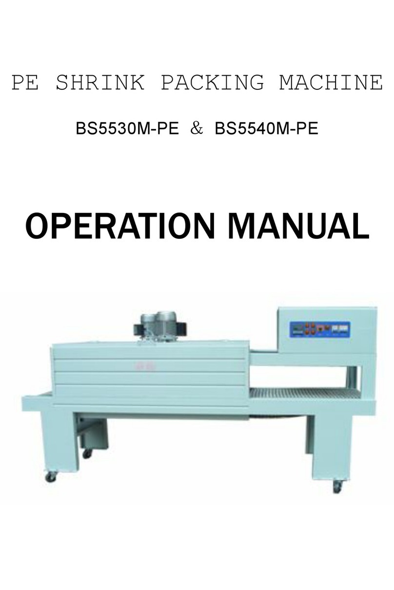
HUALIAN
HUALIAN M-PE Series Operation manual

Pro Pack Solutions
Pro Pack Solutions Eagle 710 Operation manual

Oliver
Oliver 1808-D User's operation

Kronos
Kronos H-46 Series Operation, safety and spare parts manual
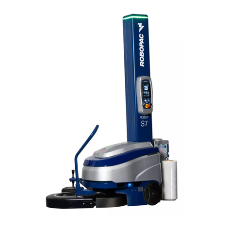
Robopac
Robopac ROBOT S7 Use and maintenance manual

