Socket & See PDL 234Plus User manual
Other Socket & See Test Equipment manuals
Socket & See
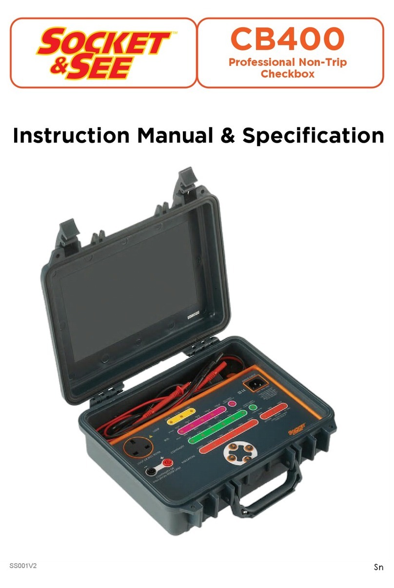
Socket & See CB400 User manual
Socket & See
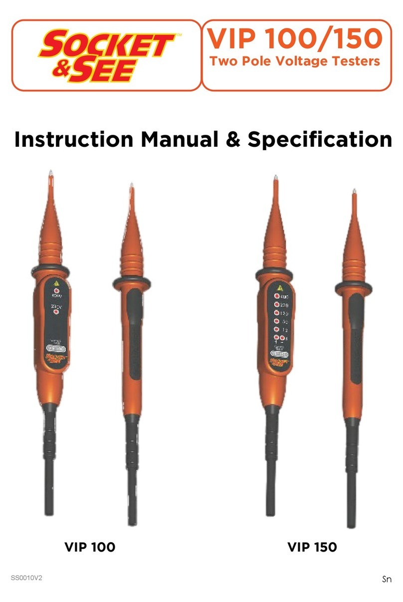
Socket & See VIP 100 User manual

Socket & See
Socket & See SP200 User manual
Socket & See
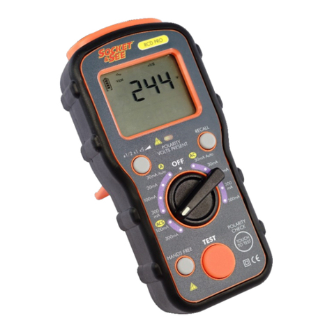
Socket & See RCD PRO User manual
Socket & See
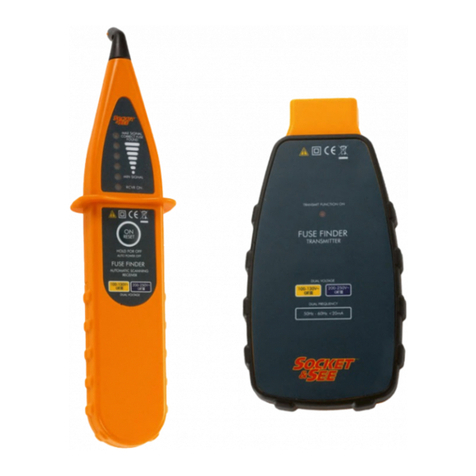
Socket & See FFCB 100 User manual
Socket & See
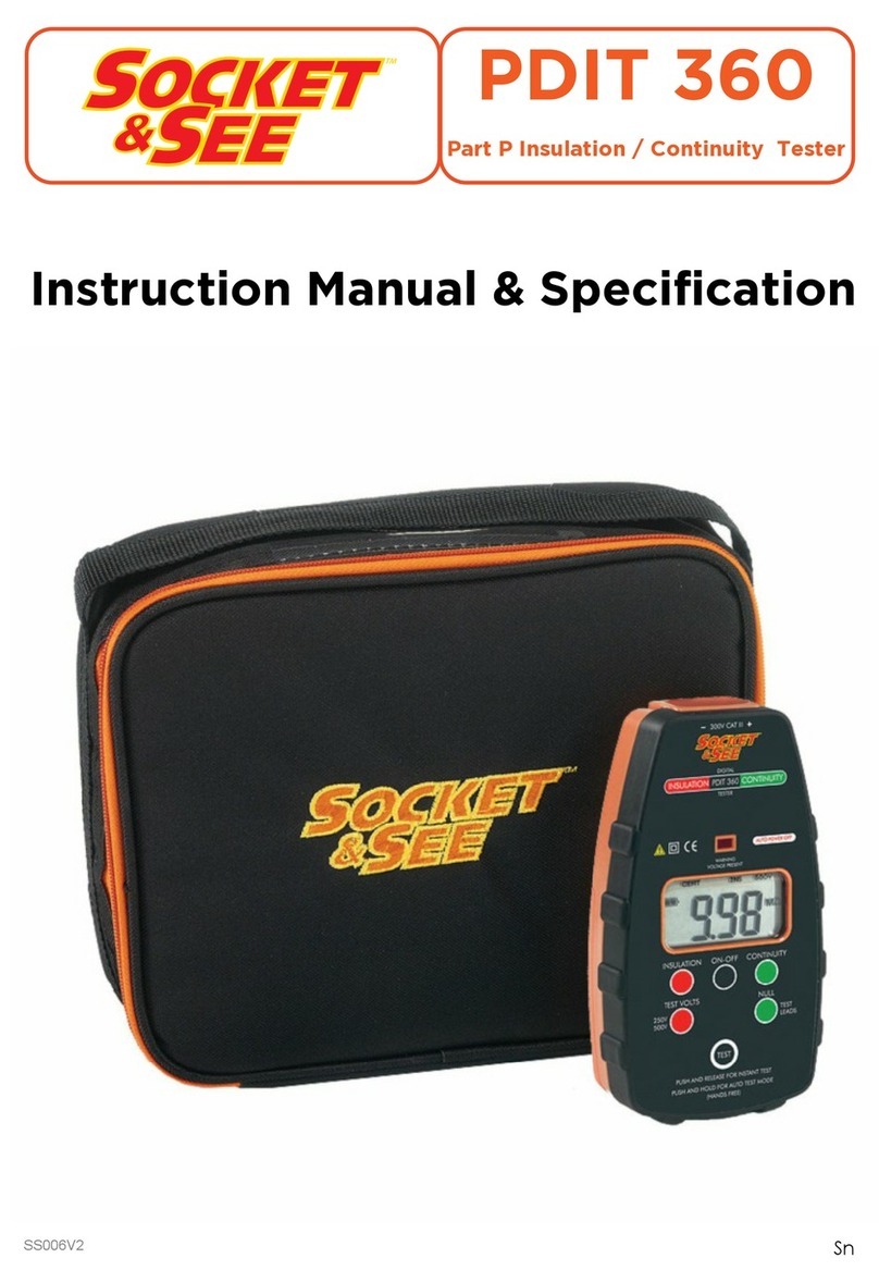
Socket & See PDIT 360 User manual
Socket & See
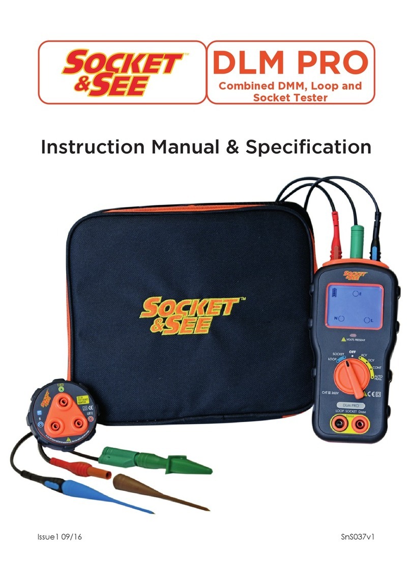
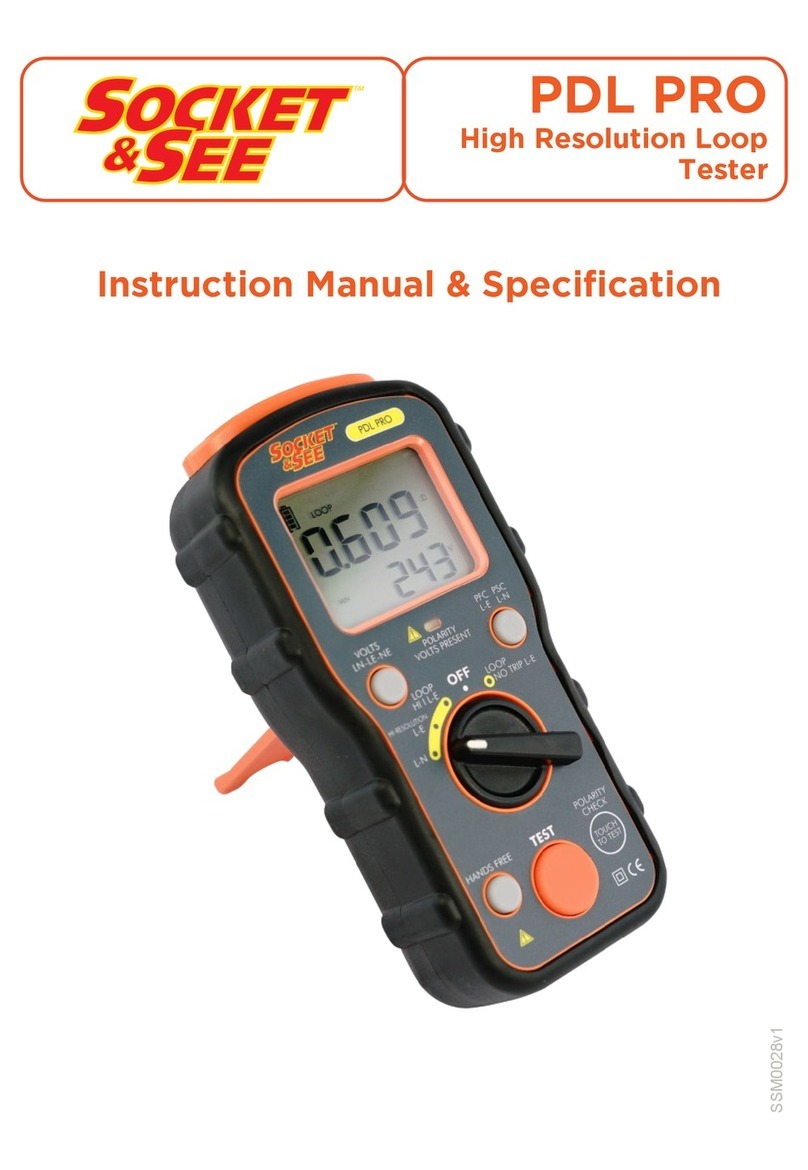
Socket & See DLM PRO User manual
Socket & See
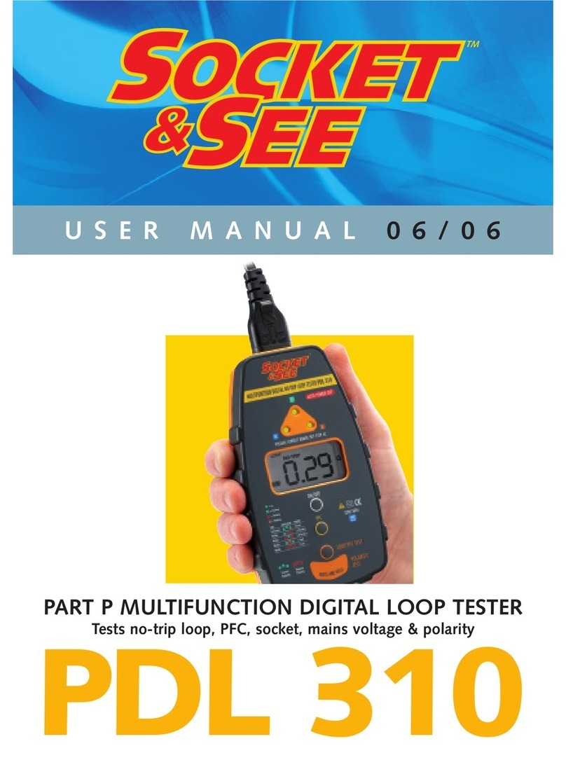
Socket & See PDL PRO User manual
Socket & See
Socket & See PDL 310 User manual

Socket & See
Socket & See PDRC 380 User manual
Popular Test Equipment manuals by other brands

Oakton
Oakton EC1 instruction manual
Keysight Technologies
Keysight Technologies 16453A Specification and Service Manual

Stahlwille
Stahlwille 7707-1-3W operating instructions
Associated Research
Associated Research 3145 Operation and service manual

Kenwood
Kenwood CO-1506 instruction manual
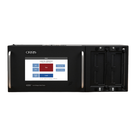
Cirris
Cirris 4200 Series Getting started guide


