socomec SUNSYS H50 User manual

SUNSYS H50
Installations- und bedienungsanleitung DE
Manuel d’installation et d’utilisation FR
Installation and operating manual GB
Manuale di installazione e uso IT


3
SUNSYS H50 - Ref.: IOMSUNHMXX05-GB 01
ENGLISH
INDEX
1. GENERAL INFORMATION . . . . . . . . . . . . . . . . . . . . . . . . . . . . . . . . . . . . . . . . . . . . . . . . . . . 4
1.1. SAFETY SYMBOLS AND INSTRUCTIONS . . . . . . . . . . . . . . . . . . . . . . . . . . . . 4
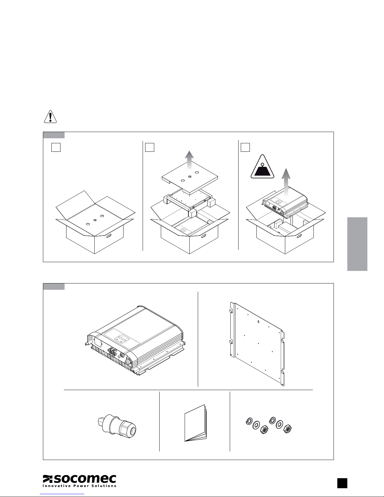
2. UNPACKING . . . . . . . . . . . . . . . . . . . . . . . . . . . . . . . . . . . . . . . . . . . . . . . . . . . . . . . . . . . . . 5
2.1. REMOVAL OF PACKAGING . . . . . . . . . . . . . . . . . . . . . . . . . . . . . . . . . . . . . . . 5
2.2. CONTENTS . . . . . . . . . . . . . . . . . . . . . . . . . . . . . . . . . . . . . . . . . . . . . . . . . . . 5
2.3. IDENTIFICATION DATA PLATE . . . . . . . . . . . . . . . . . . . . . . . . . . . . . . . . . . . . . 6
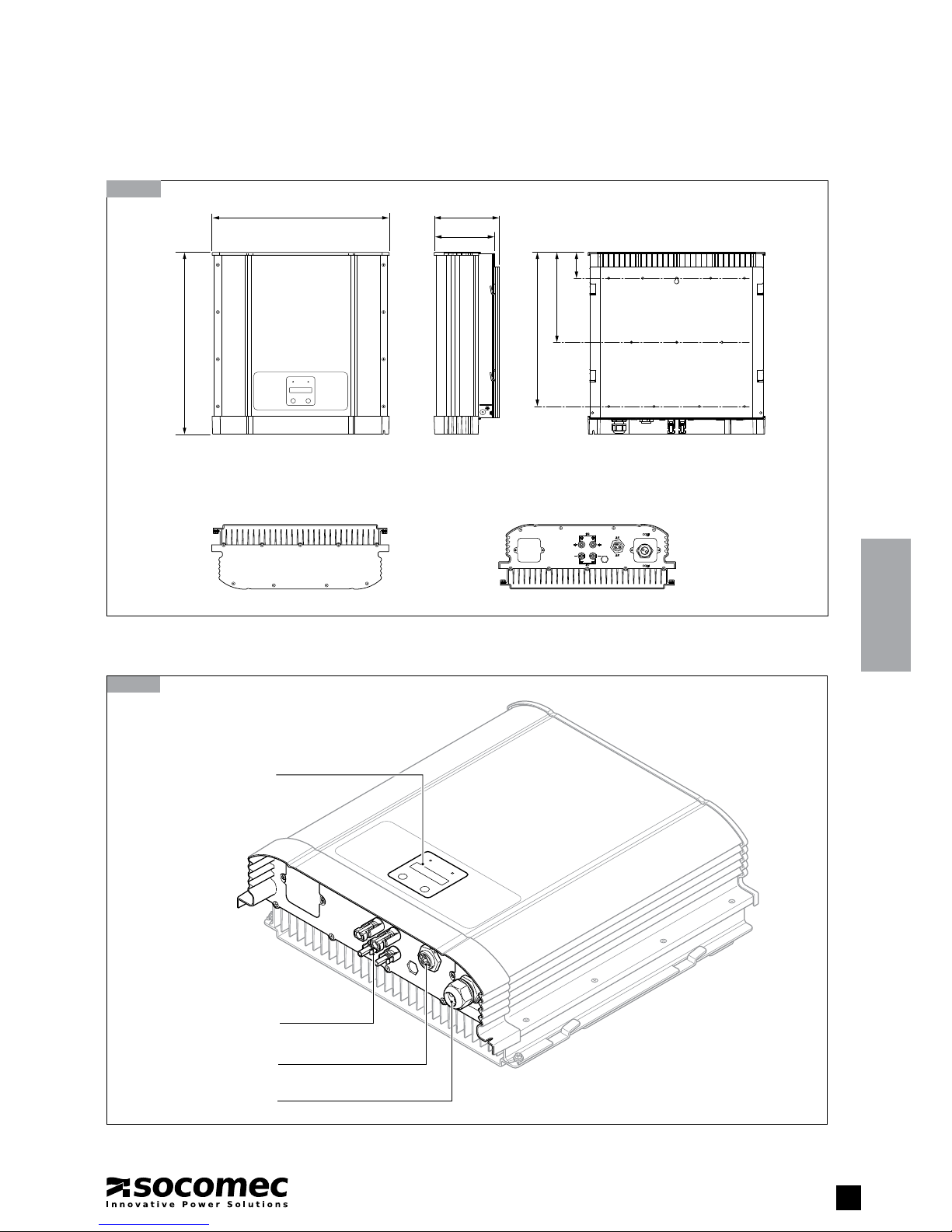
3. DESCRIPTION . . . . . . . . . . . . . . . . . . . . . . . . . . . . . . . . . . . . . . . . . . . . . . . . . . . . . . . . . . . . 7
3.1. DIMENSIONS . . . . . . . . . . . . . . . . . . . . . . . . . . . . . . . . . . . . . . . . . . . . . . . . . . 7
3.2. GENERAL DESCRIPTION OF COMPONENTS . . . . . . . . . . . . . . . . . . . . . . . . . 7
4. INSTALLATION . . . . . . . . . . . . . . . . . . . . . . . . . . . . . . . . . . . . . . . . . . . . . . . . . . . . . . . . . . . . 8
4.1. WARNINGS . . . . . . . . . . . . . . . . . . . . . . . . . . . . . . . . . . . . . . . . . . . . . . . . . . . 8
4.2. CONDITIONS FOR INSTALLATION . . . . . . . . . . . . . . . . . . . . . . . . . . . . . . . . . . 8
4.3. WALL FIXING . . . . . . . . . . . . . . . . . . . . . . . . . . . . . . . . . . . . . . . . . . . . . . . . . . 9
5. CONNECTIONS . . . . . . . . . . . . . . . . . . . . . . . . . . . . . . . . . . . . . . . . . . . . . . . . . . . . . . . . . . 10
5.1. DESCRIPTION . . . . . . . . . . . . . . . . . . . . . . . . . . . . . . . . . . . . . . . . . . . . . . . . 10
5.2. AC CONNECTION . . . . . . . . . . . . . . . . . . . . . . . . . . . . . . . . . . . . . . . . . . . . . 12
5.3. DC CONNECTION . . . . . . . . . . . . . . . . . . . . . . . . . . . . . . . . . . . . . . . . . . . . . 12
5.4. COMMUNICATION MODULE CONNECTIONS . . . . . . . . . . . . . . . . . . . . . . . . 13
6. COMMISSIONING . . . . . . . . . . . . . . . . . . . . . . . . . . . . . . . . . . . . . . . . . . . . . . . . . . . . . . . . 14
6.1. PHOTOVOLTAIC MODULE SETUP . . . . . . . . . . . . . . . . . . . . . . . . . . . . . . . . 14
6.2. AC GRID VOLTAGE REQUIREMENTS. . . . . . . . . . . . . . . . . . . . . . . . . . . . . . . 14
6.3. FIRST START-UP . . . . . . . . . . . . . . . . . . . . . . . . . . . . . . . . . . . . . . . . . . . . . . 14
7. CONTROL PANEL . . . . . . . . . . . . . . . . . . . . . . . . . . . . . . . . . . . . . . . . . . . . . . . . . . . . . . . . 16
8. MENU . . . . . . . . . . . . . . . . . . . . . . . . . . . . . . . . . . . . . . . . . . . . . . . . . . . . . . . . . . . . . . . . . 17
8.1. DESCRIPTION . . . . . . . . . . . . . . . . . . . . . . . . . . . . . . . . . . . . . . . . . . . . . . . . 17
8.2. SETTINGS . . . . . . . . . . . . . . . . . . . . . . . . . . . . . . . . . . . . . . . . . . . . . . . . . . . 19
8.3. SELF-TEST . . . . . . . . . . . . . . . . . . . . . . . . . . . . . . . . . . . . . . . . . . . . . . . . . . . 21
9. MESSAGES . . . . . . . . . . . . . . . . . . . . . . . . . . . . . . . . . . . . . . . . . . . . . . . . . . . . . . . . . . . . . 22
9.1. ERROR MESSAGES . . . . . . . . . . . . . . . . . . . . . . . . . . . . . . . . . . . . . . . . . . . . 22
9.2. FAULT MESSAGES . . . . . . . . . . . . . . . . . . . . . . . . . . . . . . . . . . . . . . . . . . . . . 23
10. REMOVAL OF INVERTER. . . . . . . . . . . . . . . . . . . . . . . . . . . . . . . . . . . . . . . . . . . . . . . . . . 25
11. TECHNICAL SPECIFICATIONS. . . . . . . . . . . . . . . . . . . . . . . . . . . . . . . . . . . . . . . . . . . . . . 26

4SUNSYS H50 - Ref.: IOMSUNHMXX05-GB 01
4
This user manual specifies installation and maintenance procedures, technical data and safety instructions for SOCOMEC solar
inverters. For further information visit the Socomec website: www.socomec.com.
Any work carried out on the equipment must be performed by skilled, qualified technicians.
1.1. SAFETY SYMBOLS AND INSTRUCTIONS
WARNING!
Failure to observe safety standards could result in fatal accidents or serious injury, and damage
equipment or the environment.
WARNING!
Device with several power supply sources.
In the event of system maintenance, carry out the following steps beforehand:
- Open the AC switch.
- Open the DC switch.
- Make sure the system cannot be restarted.
- Make sure the electricity supply has been disconnected.
WARNING! RISK OF ELECTRIC SHOCK!
The equipment includes capacitors that store energy. After disconnecting all power sources wait for
the capacitors to discharge.
WARNING! RISK OF BURNS!
During operation the temperature of the casing may exceed 70 °C. Do not touch the surfaces!
Keep this manual safe for future reference.
Before carrying out any operations on the inverter read the Installation and Operating Manual carefully.
Do not dispose of the inverter with normal household waste.
At the end of its working life, the inverter must be disposed of in accordance with local regulations for
the disposal of electronic components applicable to the installation site at the moment of disposal.
The following precautions must be taken in order to avoid risks of overheating, fire. electric shock, mechanical shock, and collateral
damage (persons and/or property):
• Do not cover or obstruct the inverter.
• Do not install the inverter inside a cabinet in an enclosed, non-ventilated area.
• When installing the inverter comply with the recommended clearances (see chapter 4.2).
• Only use accessories recommended or sold by the manufacturer.
• Ensure the wiring is in good condition and not undersized.
• Do not operate the inverter with damaged or substandard wiring.
• Do not operate the inverter if it has suffered a violent mechanical shock of any kind (fall, impact, etc.)
• Before cleaning or performing maintenance work on the inverter or connected appliances, disconnect the power sources. After
disconnecting wait for the internal capacitors to discharge completely (5 minutes approx).
• Inverter earth connection. See Chapter 5.
1. GENERAL INFORMATION

5
SUNSYS H50 - Ref.: IOMSUNHMXX05-GB 01
ENGLISH
2.1-1
2.2-1
2. UNPACKING
2.1. REMOVAL OF PACKAGING
Materials can be disturbed during transport. Check the packaging is not damaged.
After removing the packaging ensure that:
• the data plate details on the left hand side of the inverter correspond to those of the model purchased;
• all accessories are included in the package.
WARNING!
If the inverter is found to be damaged externally or internally, or any of the accessories are damaged or missing,
contact SOCOMEC.
00,0 kg
1 2 3
INSTALLATION AND
OPERATING MANUAL
2.2. CONTENTS
Photovoltaic inverter
AC connector Documentation Nut and washer for inverter mounting
Bracket

6SUNSYS H50 - Ref.: IOMSUNHMXX05-GB 01
6
2.3. IDENTIFICATION DATA PLATE
2.3-1
2 GENERAL INFORMATION
Model
Technical data
Serial number

7
SUNSYS H50 - Ref.: IOMSUNHMXX05-GB 01
ENGLISH
3.2-1
3. DESCRIPTION
3.1. DIMENSIONS
LCD display and
control panel
Communication port
Output connection
Input connection
68
238
408
159
172469
482
3.1-1
3.2. GENERAL DESCRIPTION OF COMPONENTS

8SUNSYS H50 - Ref.: IOMSUNHMXX05-GB 01
4. INSTALLATION
4.1. WARNINGS
The inverter is designed for mounting on masonry walls. If the walls are made using different materials, the installer must use suitable
mounting supports.
Install the inverter in an equipment room where only skilled technicians have access. The room must be:
• of a suitable size;
• clean;
• free from inflammable items;
• not exposed directly to sunlight;
• maintained at a temperature between -20 °C and 40 °C.
4.2. CONDITIONS FOR INSTALLATION
4.2-1

9
SUNSYS H50 - Ref.: IOMSUNHMXX05-GB 01
ENGLISH
INSTALLATION
4.3. WALL FIXING
4.2-2 Suitable installation clearances
50 cm
50 cm
50 cm
50 cm
30 cm 30 cm 30 cm
4.3-1
90
120
170
170
120
120 120 120
90 90 90
5 viti M6
3 viti M6
4 viti M6

10 SUNSYS H50 - Ref.: IOMSUNHMXX05-GB 01
DC
DC
AC
AC
COM
COM
5. CONNECTIONS
5.1-1
5.1. DESCRIPTION
WARNING!
carry out the following steps beforehand:
- Open the AC switch.
- Open the DC switch.
- Make sure the system cannot be restarted.
- Make sure the electricity supply has been disconnected.
B
efore connecting the power supply connect the earth cable (PE).
Before connecting any cables to the inverter, check that the polarity, voltage and sequence of the phases are
correct.
Check that the input and output cables of the photovoltaic system are clearly identified.
PV module inputs
DC = 2 strings in parallel
AC output, with
connections
L1, N, and PE
External
communication
interface
PE Ground
connection

11
SUNSYS H50 - Ref.: IOMSUNHMXX05-GB 01
ENGLISH
5.1-3 Connecting the PV system to positive or negative earth
5.1-2 Connection of the PV system without earth connection
Note
with a floating DC input (no earth connection) no isolating transformer is required.
DC1
1L
2N
PE
or
z
z
A transformer must be
installed
Isolating transformer
Load
1 Ph +N
230 Vac
Inverter
1 Ph +N
230 Vac
Photovoltaic panels DC distribution
panel
AC connections
Photovoltaic panels
DC distribution panel
(GND+ or GND-)
Note
With DC input connected to earth (one pole connected to earth) isolating transformer is required.
Refer to par 6.3 for ground option setting

12 SUNSYS H50 - Ref.: IOMSUNHMXX05-GB 01
12
5. CONNECTIONS
5.2. AC CONNECTION
• Before wiring the AC side ensure the AC mains supply is disconnected.
• Check that the connection cable used matches the specifications in the table.
Sizing of AC cables
Model Max current Cross-section Fastening Circuit breaker Residual current protection
SUNSYS-H50 25 A 4 mm2≥ 0.8 Nm MCCB rated 32 A 1P+N curve C 0.3 A type A or AC
The AC connection is made with a single pole plug (L1, N, PE - see diagram).
5.2-1
N
L
PE
00
00
N
L
PE
Inverter
N
L
PE
3
12
4
5.3-1
5.3. DC CONNECTION
• Before wiring the DC side ensure the DC power supply is disconnected.
• Check that the connection cable used matches the specifications in the table.
Sizing of DC cables
Model Max current Cross-section
SUNSYS-H50 17.5 ADC 4 mm2
DC connections are divided into positive and negative poles.
RED
BLACK

13
SUNSYS H50 - Ref.: IOMSUNHMXX05-GB 01
ENGLISH
5. CONNECTIONS
5.4-1 Communication module
RS485 PIN Layout
PIN FUNCTION
4 DATA -
5 DATA +
7 GND
5.4.3-1
RS485/USB
or
RS485/RS232
PIN Layout
PIN FUNCTION
4 DATA -
5 DATA +
7 GND
Data Format
Baud Rate: 9600
Data bits: 8
Stop bit: 1
Parity: N/A
5.3.1. RS-485 serial port
The communication terminal block allows connection to one or more inverter units.
5.4. COMMUNICATION MODULE CONNECTIONS
120 Ω (1/2 W)
DATA + to DATA –
Terminal
Resistor

14 SUNSYS H50 - Ref.: IOMSUNHMXX05-GB 01
14
6. COMMISSIONING
6.1. PHOTOVOLTAIC MODULE SETUP
• The maximum no-load DC voltage of the photovoltaic field must be no higher than 1000 V.
• The maximum connection power going to the inverter must be no greater than 5600 W.
• The breaker device must have a maximum rated voltage of > 1000 Vdc and maximum short-circuit current > 17.5A.
• The voltage range of the MPPTs must be between 310 V and 850 V.
6.2. AC GRID VOLTAGE REQUIREMENTS
Nominal voltage and current. See Chapter 5.
•
An AC(1) automatic circuit breaker must be installed and allocated to each of the solar inverters, independently of the system (see heading 5.2).
Grid voltage values
L1-N 230 Vac
The inverter is fitted with a unit which monitors and detects fault currents; this is sensitive to all types of ground fault current.
We recommend the application of an external type A or AC 30 mA differential protection device with low sensitivity (S).
(1) Or similar protection on the basis of current regulations
6.3. FIRST START-UP
Check that the AC, DC and communication connections are made and secured correctly.
WARNING!
If the country setting is wrong SOCOMEC must be contacted for assistance.
1. Power up the inverter (AC or DC)
2. Set the country.
• use ent button to enter the country selection menu
• use sel button to find your country(1)
• use ent button to select the country
• use ent button to set the chosen country
• use sel button for next menu.
3. Set insulation mode.
• use ent button to enter the insulation mode selection menu
• use sel button to find the plant insulation mode
• use ent button to select this insulation mode
• use ent button to set the chosen insulation mode
• use sel button for next menu.
4. Set the language.
• use ent button to enter the laguage selection menu
• use sel button to find your language
• use ent button to select this language
• use ent button to set the chosen language
• use ent button to confirm and start the inverter.
If the level of sunlight is sufficient the inverter will come into operation.
During subsequent start-ups the device will show the main page of the menu.
(1) select "ITALY NO SPI" for Italian installation where the plant power is > 6 kw (an external SPI is mandatory)

15
SUNSYS H50 - Ref.: IOMSUNHMXX05-GB 01
ENGLISH
SEL ENT
SEL ENT SEL ENT SEL ENT
SEL ENT
SEL ENT
6.3-1 Country and language selection menu
6. COMMISSIONING
Country
xxx
Italy
Next Enter
France
Next Enter
Exit
N Y
Italy
N Y
Country
Italy
SEL ENT
SEL ENT SEL ENT SEL ENT
SEL ENT
SEL ENT
Insulation mode
xxx
Normal
Next Enter
Negative
Next Enter
Normal
N Y
Ground option
Normal
Exit
N Y
SEL ENT
SEL ENT SEL ENT SEL ENT
SEL ENT
SEL ENT
Language
xxx
English
Next Enter
Italian
Next Enter
Exit
N Y
English
N Y
Language
English
SEL and ENT are pressed
simultaneously > 30 sec.
SEL ENT
Exit
N Y Inverter
On
SEL ENT
SEL ENT SEL ENT SEL ENT
SEL ENT
SEL ENT
AC connect
xxx
L-N
Next Enter
L1-L2
Next Enter
Exit
N Y
L-N
N Y
AC connect
L-N

16 SUNSYS H50 - Ref.: IOMSUNHMXX05-GB 01
16
7.1-1
7. CONTROL PANEL
WARNING! RISK OF ACCIDENT OR SERIOUS INJURY!
Do not touch the terminal of the photovoltaic module when exposed to sunlight
SELECT ENTER
ALARMON
LED indicator
Condition Green LED Red LED
Countdown FLASHING OFF
On grid ON OFF
Error or Fault OFF ON
Standby or night-time (no DC supply) OFF OFF
FW update FLASHING FLASHING
Move to next menu
LCD display
LED red
Confirm
LED green

17
SUNSYS H50 - Ref.: IOMSUNHMXX05-GB 01
ENGLISH
8.1-2 Measurements
8.1-1 Daily energy (main menu)
Actual power generated
Total energy generated during the day
Mains voltage and frequency
Inverter output current
PV array voltage, current and power
Today input energy
Output AC energy production from installation
PV array DC energy production from installation
8. MENU
WARNING!
The menus and settings described are visible only after the appliance has been started up for the first time. See
Chapter 6.
8.1. DESCRIPTION
SEL ENT
Output 3600W
Today 7200Wh
Actual output power
Daily output energy
SEL ENT
SEL ENT
SEL ENT
SEL ENT
SEL ENT
SEL ENT
SEL ENT
Output 3600W
Today 7200Wh
Utility
225V 50.00Hz
Output current
16.0A
DC: 320V
5.9A 1894W
Today DC
7500Wh
AC life energy
1450kWh
DC life energy
1540kWh
Use sel button to move through the menu available

18 SUNSYS H50 - Ref.: IOMSUNHMXX05-GB 01
18
8.1-4 Event log
8.1-3 Inverter information
8. MENU
This page displays the last sixteen events (error or fault) recorded by the system. The first event displayed is the most recent.
Inverter rating
Inverter firmware version
SEL ENT
SEL ENT
Inverter
5.0kVA
DSP comm red.
0000 0000 0000
Push ENT button to cancel
the event log
SEL ENT
SEL ENT
SEL ENT
SEL ENT
SEL ENT
SEL ENT
Event List
Enter
01 : Grid freq
under rating
02 : Grid volt
under rating
03 : empty
16 : empty
Clear Event Logs
Exit Yes

19
SUNSYS H50 - Ref.: IOMSUNHMXX05-GB 01
ENGLISH
8.2.1-1
Inverter ID
8.2. SETTINGS
8.2.1. Installation settings
WARNING! DAMAGE CAN BE CAUSED TO THE MACHINE AND SYSTEM!
The following settings are enabled and managed by the grid operator, installer or specialist technician.
Wrong settings are liable to damage the photovoltaic system.
For any modification requested by the grid operator, or special configuration, please contact Socomec
for assistance
• Inverter ID
Address of each inverter.
8. MENU
SEL ENT
SEL ENT
SEL ENT
Inverter
ID : XX
Setting ID
ID = XX ?
Setting ID
ID = XX+1 ?
SEL ENT
Setting ID
ID = XX+10 ?
SEL is pressed
> 2 sec.
SEL and ENT
are pressed
simultaneously
> 3 sec.

20 SUNSYS H50 - Ref.: IOMSUNHMXX05-GB 01
20
8. MENU
8.2.1-2 Local command only for Italy as country
SEL ENT
Comando locale
off
SEL ENT
SEL ENT SEL ENT
SEL ENT
SEL ENT
Off
Next / Enter
On
Next / Enter
Exit
N Y
On
N Y
Are you sure ?
N Y
SEL ENT
Comando locale
Attivo
SEL ENT
Password
Push: SEL, ENT, ENT, SEL, SEL, ENT
After 10 second or PW faill
SEL ENT
SEL ENT
Country
xxx
Language
xxx
SEL ENT
Insulated mode
xxx
Other manuals for SUNSYS H50
1
Table of contents
Other socomec Inverter manuals
Popular Inverter manuals by other brands

Tektronix
Tektronix SPG 422 Service manual

Westinghouse
Westinghouse WH7500v quick start guide

Northern Lights
Northern Lights M1064D Operator's manual

Fuji Electric
Fuji Electric Frenic Mega Series user manual

Mitsubishi Electric
Mitsubishi Electric 800 Series instruction manual

Mecc Alte
Mecc Alte ECO-ECP 4 Operating and maintenance instructions