manuals.online logo
Brands
  1. Home
  2. •
  3. Brands
  4. •
  5. socomec
  6. •
  7. Switch
  8. •
  9. socomec ATyS User manual

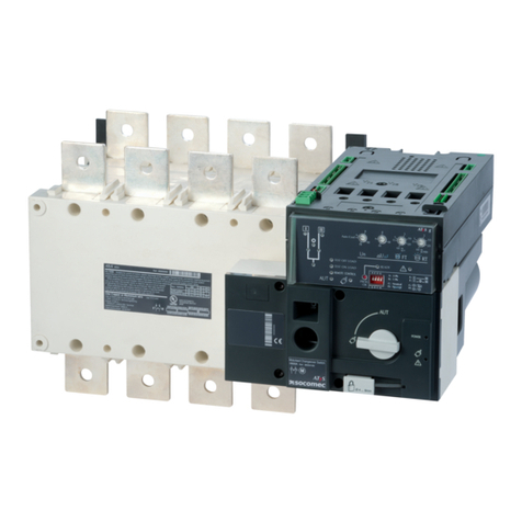
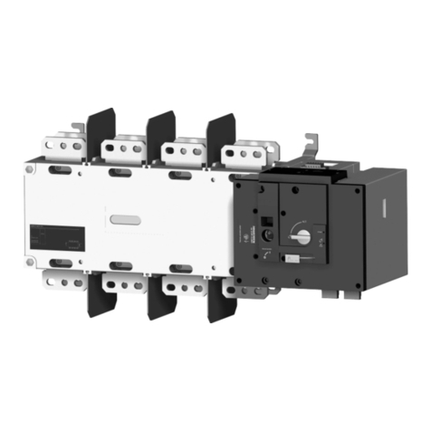
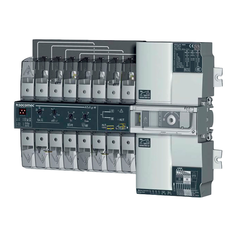
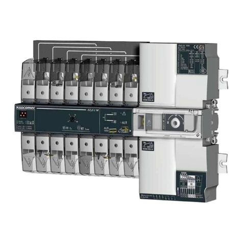
socomec ATyS User manual

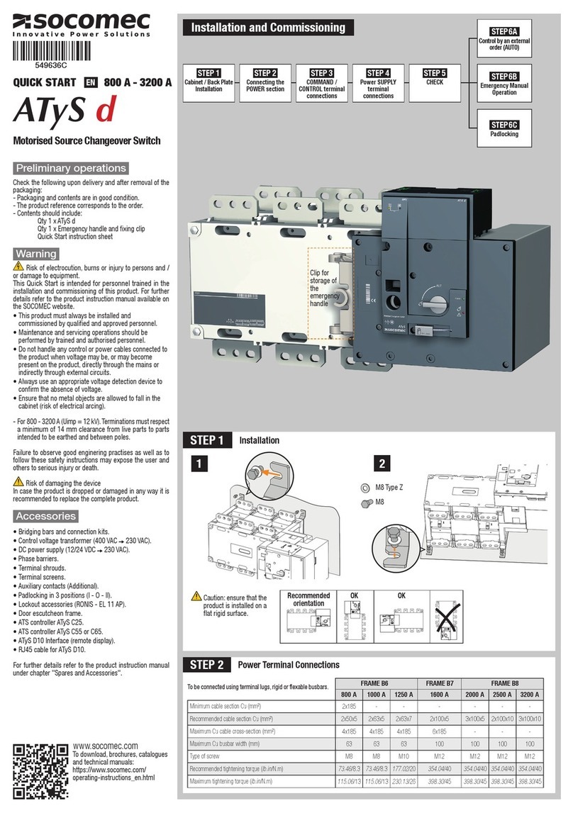
QUICK START 125 A-630 A
ATyS / ATyS r
1
3
2
Max.
0.51 in.
13 mm.
125 A 160 A 200 A 250 A 315 A 400 A 500 A 630 A
35 35 50 95 120 185 2x95 2x120
- - - - - - 2x32x5 2x40x5
50 95 120 150 240 240 2x185 2x300
25 25 25 32 32 32 50 50
M8 M8 M8 M10 M10 M10 M12 M12
73.46/8.3 73.46/8.3 73.46/8.3 177.02/20 177.02/20 177.02/20 354.04/40 354.04/40
115.06/13 115.06/13 115.06/13 230.13/26 230.13/26 230.13/26 398.30/45 398.30/45
STEP 2
STEP 1
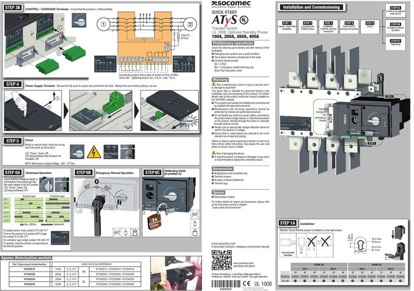
Preliminary operations
Check the following upon delivery and after removal of the
packaging:
- Packaging and contents are in good condition.
- The product reference corresponds to the order.
- Contents should include:
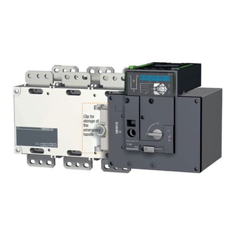
Qty 1 x ATyS / ATyS r
Qty 1 x Emergency handle and fixing clip
Quick Start instruction sheet
Warning
Risk of electrocution, burns or injury to persons and /
or damage to equipment.
This Quick Start is intended for personnel trained in the
installation and commissioning of this product. For further
details refer to the product instruction manual available on
the SOCOMEC website.
• This product must always be installed and
commissioned by qualified and approved personnel.
• Maintenance and servicing operations should be
performed by trained and authorised personnel.
• Do not handle any control or power cables connected to
the product when voltage may be, or may become
present on the product, directly through the mains or
indirectly through external circuits.
• Always use an appropriate voltage detection device to
confirm the absence of voltage.
• Ensure that no metal objects are allowed to fall in the
cabinet (risk of electrical arcing).
- For 125 - 160 A (Uimp = 8 kV). Terminations must respect
a minimum of 8 mm clearance from live parts to parts
intended to be earthed and between poles.
- For 200 - 630 A (Uimp = 12 kV). Terminations must respect
a minimum of 14 mm clearance from live parts to parts
intended to be earthed and between poles.
Failure to observe good enginering practises as well as to
follow these safety instructions may expose the user and
others to serious injury or death.
Risk of damaging the device
In case the product is dropped or damaged in any way it is
recommended to replace the complete product.
Accessories
• Bridging bars and connection kits.
• Control voltage transformer (400 VAC 230 VAC).
• DC power supply (12/24 VDC 230 VAC).
• Phase barriers.
• Terminal shrouds.
• Terminal screens.
• Auxiliary contacts (Additional).
• Padlocking in 3 positions (I - O - II).
• Lockout accessories (RONIS - EL 11 AP).
• Door escutcheon frame.
• ATS controller ATyS C25.
• ATS controller ATyS C55 or C65.
For further details refer to the product instruction manual
under chapter "Spares and Accessories".
www.socomec.com
To download, brochures, catalogues
and technical manuals:
https://www.socomec.com/
operating-instructions_en.html
549603D
Motorised Source Changeover Switch
EN
Installation and Commissioning
Installation
3
500 A, 630 A.125 A to 400 A.
Mounting Removing covers
Power Terminal Connections
FRAME B3 FRAME B4 FRAME B5
Minimum cable section Cu (mm2)
Recommended Cu busbar cross-section (mm2)
Maximum Cu cable cross-section (mm2)
Maximum Cu busbar width (mm)
Type of screw
Recommended tightening torque(lb.in/N.m)
Maximum tightening torque (lb.in/N.m)
M8 Type Z
M8
Caution: ensure
that the product
is installed on a
flat rigid surface.
Recommended
orientation
OKOK
STEP 1
Cabinet / Back Plate
Installation
STEP 3
COMMAND /
CONTROL terminal
connections
STEP 2
Connecting the
POWER section
STEP 4
Power SUPPLY
terminal
connections
STEP 5
CHECK
STEP 6A
Control by an external
order (AUTO)
STEP 6C
Padlocking
STEP 6B
Emergency Manual
Operation
To be connected using terminal lugs, rigid or flexable busbars.
Clip for
storage of
the
emergency
handle
1
2
2
1
3
125 A 160 A 200 A 250 A
3 P 4 P 3 P 4 P 3 P 4 P 3 P 4 P
in mm in mm in mm in mm in mm in mm in mm in mm
C
9.61 244 9.61 244 9.61 244 9.61 244 9.61 244 9.61 244 9.61 244 9.61 244
CA
0.39 10 0.39 10 0.39 10 0.39 10 0.39 10 0.39 10 0.59 15 0.59 15
F
11.28 286,5 12.48 317 11.28 286,5 12.48 317 11.28 286,5 12.48 317 12.91 328 14.88 378
M
4.72 120 5.91 150 4.72 120 5.91 150 4.72 120 5.91 150 6.30 160 8.27 210
T
1.42 36 1.42 36 1.42 36 1.42 36 1.42 36 1.42 36 1.97 50 1.97 50
U
0.79 20 0.79 20 0.79 20 0.79 20 0.79 20 0.79 20 0.98 25 0.98 25
W
0.35 90.35 90.35 90.35 90.35 90.35 90.43 11 0.43 11
X
1.10 28 0.87 22 1.10 28 0.87 22 1.10 28 0.87 22 1.30 33 1.30 33
315 A 400 A 500 A 630 A
3 P 4 P 3 P 4 P 3 P 4 P 3 P 4 P
in mm in mm in mm in mm in mm in mm in mm in mm
C
9.61 244 9.61 244 9.61 244 9.61 244 12.64 321 12.64 321 12.64 321 12.64 321
CA
0.59 15 0.59 15 0.59 15 0.59 15 0.59 15 0.59 15 0.79 20 0.79 20
F
12.91 328 14.88 378 12.91 328 14.88 378 14.84 377 17.20 437 14.84 377 17.20 437
M
6.30 160 8.27 210 6.30 160 8.27 210 8.27 210 10.63 270 8.27 210 10.63 270
T
1.97 50 1.97 50 1.97 50 1.97 50 2.56 65 2.56 65 2.56 65 2.56 65
U
1.38 35 1.38 35 1.38 35 1.38 35 1.26 32 1.26 32 1.77 45 1.77 45
W
0.43 11 0.43 11 0.43 11 0.43 11 0.55 14 0.55 14 0.51 13 0.51 13
X
1.30 33 1.30 33 1.30 33 1.30 33 1.67 42,5 1.48 37,5 1.67 42,5 1.48 37,5
W
U
CA
5.43
138
3.98
101
X T
Fix. M
F
C
Fix. 7.38
187,5
0.83
21
9.04
229,5
0.49
12,5
0.30
7,5
0.34
8,6
0.64
16,2
0.64
16,2
0.34
8,6
AUT
90°
90°
I II
0
3x
Ø4-8 mm
12
3013022
312313 314315 316317 63A64A 24 14 04 13
CONTROL OUTPUTS
Imp. ≥60ms maintened
To enable control, close contact 312 with 317.
To force the product to 0 position/OFF bridge the contact
313 with 317. For contactor logic bridge contact 316
with 317. To operate: close the contact corresponding
to the desired position.
Connect the product with a cable of
section of 1,5 to 2,5 mm
2
.
Screw M3 - Tightening torque:
min.: 0.5 Nm - max.: 0.6 Nm
min.: 4.43 lbin - max.: 5.31 lbin
ATyS Voltage
Sensing and
Power supply
Kit excludes the
need for fuses
F1 & F2.
Ensure that the product is in Manual Mode.
CONTROL / COMMAND Terminals
STEP 3
STEP 5
Check
Whilst in manual mode, check
the wiring and if ok power up the
product.
LED “Power” Green: ON
LED Manuel/Defaut Red
(Productnot Available): ON
Power Supply Terminal
Remove the Top cover to access and connect the terminal - Replace the cover before putting in service.
STEP 4
Dimensions in./mm.
STEP 6A
Automatic Operation
Ensure that the emergency handle is not
inserted in the product and turn the mode
selector to the AUT position.
LED “Power” Green: ON
LED Manuel/Default: OFF
Manual Operation
Padlocking Mode
(as standard : in position O)
STEP 6C
STEP 6B
Non contractual document.
Subject to change without notice.CORPORATE HQ CONTACT: SOCOMEC SAS 1-4 RUE DE WESTHOUSE - 67235 BENFELD, FRANCE - WWW.SOCOMEC.COM
Contactor logicImpulse logic
order I
position I
order 0
position 0
order II
position II

Other manuals for ATyS

3

This manual suits for next models

1

Other socomec Switch manuals

socomec SIRCO M 16 User manual

socomec

socomec SIRCO M 16 User manual

socomec 30A User manual

socomec

socomec 30A User manual

socomec 16A User manual

socomec

socomec 16A User manual

socomec SIRCO 100A User manual

socomec

socomec SIRCO 100A User manual

socomec ATyS t User manual

socomec

socomec ATyS t User manual

socomec ATyS d M User manual

socomec

socomec ATyS d M User manual

socomec SIRCO PV 600A User manual

socomec

socomec SIRCO PV 600A User manual

socomec ATyS FT User manual

socomec

socomec ATyS FT User manual

socomec ATyS 12SA Guide

socomec

socomec ATyS 12SA Guide

socomec SIRCO MOT PV UL User manual

socomec

socomec SIRCO MOT PV UL User manual

socomec ATyS t User manual

socomec

socomec ATyS t User manual

socomec ATyS g M User manual

socomec

socomec ATyS g M User manual

socomec ATyS g M User manual

socomec

socomec ATyS g M User manual

socomec SIRCO PV Series User manual

socomec

socomec SIRCO PV Series User manual

socomec STATYS XS 16A User manual

socomec

socomec STATYS XS 16A User manual

socomec ATyS Series User manual

socomec

socomec ATyS Series User manual

socomec ATyS t M User manual

socomec

socomec ATyS t M User manual

socomec COMO CS 25A User manual

socomec

socomec COMO CS 25A User manual

socomec ATyS User manual

socomec

socomec ATyS User manual

socomec ATyS Series User manual

socomec

socomec ATyS Series User manual

socomec SIRCOVER 400A User manual

socomec

socomec SIRCOVER 400A User manual

socomec INOSYS LBS Series User manual

socomec

socomec INOSYS LBS Series User manual

socomec ATyS r User manual

socomec

socomec ATyS r User manual

socomec SIDER User manual

socomec

socomec SIDER User manual

Popular Switch manuals by other brands

Dell PowerConnect 8024 User configuration guide

Dell

Dell PowerConnect 8024 User configuration guide

Linksys SR224G - Cisco - 10/100 Gigabit Switch Product data

Linksys

Linksys SR224G - Cisco - 10/100 Gigabit Switch Product data

Dwyer Instruments Mini-Photohelic MP Series Installation and operating instructions

Dwyer Instruments

Dwyer Instruments Mini-Photohelic MP Series Installation and operating instructions

Avocent DSR Series DSR1020 Hardware specifications

Avocent

Avocent DSR Series DSR1020 Hardware specifications

Kramer VM-218DTxr quick start guide

Kramer

Kramer VM-218DTxr quick start guide

Kohler KSS Series Installation

Kohler

Kohler KSS Series Installation

D-Link DGS-3312SR Command line interface reference manual

D-Link

D-Link DGS-3312SR Command line interface reference manual

ZyXEL Communications Dimension ES-3024 Specifications

ZyXEL Communications

ZyXEL Communications Dimension ES-3024 Specifications

StarTech.com SDOCK2U33HFW instruction manual

StarTech.com

StarTech.com SDOCK2U33HFW instruction manual

NETGEAR ProSAFE JGS524Ev2 installation guide

NETGEAR

NETGEAR ProSAFE JGS524Ev2 installation guide

Uniclass AI-CP02A Quick installation guide

Uniclass

Uniclass AI-CP02A Quick installation guide

Endress+Hauser Flowphant T DTT31 operating instructions

Endress+Hauser

Endress+Hauser Flowphant T DTT31 operating instructions

Feeltek FLT005a user manual

Feeltek

Feeltek FLT005a user manual

D-Link DAS-3224 user manual

D-Link

D-Link DAS-3224 user manual

H3C S7500 Series Operation manual

H3C

H3C S7500 Series Operation manual

Panasonic WJ-SW208 Specifications

Panasonic

Panasonic WJ-SW208 Specifications

Niles LS-1 Specification sheet

Niles

Niles LS-1 Specification sheet

LevelOne FSW-1610TX Specification sheet

LevelOne

LevelOne FSW-1610TX Specification sheet

manuals.online logo
manuals.online logoBrands
  • About & Mission
  • Contact us
  • Privacy Policy
  • Terms and Conditions

Copyright 2025 Manuals.Online. All Rights Reserved.