Solar-Log 300 Instruction manual
1
Meter Connection Manual
Solar-Log™
EN

2
Publisher:
Solare Datensysteme GmbH
Fuhrmannstr. 9
72351 Geislingen-Binsdorf
Germany
International support
Tel.:+49 7428 9418 -640
Fax:+49 7428 9418 -280
e-mail: [email protected]
Italy
Technical support: +39 0471 631032
e-mail: [email protected]
France
Technical support: +33 97 7909708
e-mail: [email protected]
Switzerland
Technical support: +41 565 355346
United States
Technical support: +1 203 702 7189
e-mail: [email protected]

3
Table of Contents
1 External Power Meter ................................................................................................. 4
1.1 Recording Energy Flows with External Power Meters.................................................................................. 4
2 Solar-Log™ Meter Operating Modes ..................................................................... 5
2.1 Explanation of the Solar-Log™ Meter Operating Modes ............................................................................. 5
3 General Information on Wiring................................................................................ 6
3.1 Wiring for S0 meter .................................................................................................................................................... 6
3.2 Wiring for RS485 meter ............................................................................................................................................ 6
3.3 Wiring meters to record self-consumption........................................................................................................ 6
4 Solar-Log™ PRO380 Mod.......................................................................................... 9
4.1 Solar-Log™ PRO380 Mod.......................................................................................................................................... 9
5 Inepro...............................................................................................................................12
5.1 Inepro 1250D................................................................................................................................................................ 12
5.2 Inepro 75D .................................................................................................................................................................... 14
6 Iskra ..................................................................................................................................16
6.1 Iskra WS0021 ............................................................................................................................................................... 16
6.2 Iskra WS0031 ............................................................................................................................................................... 17
7 Janitza UMG 104 (Utility Meter) ............................................................................18
7.1 Janitza UMG 104......................................................................................................................................................... 18
4
External Power Meter
Recording Energy Flows with External Power Meters
1 External Power Meter
1.1 Recording Energy Flows with External Power Meters
External power meters can be connected to every Solar-Log™ model via the S0 input and/or the RS-485
bus.
Solar-Log™ devices have a varying number of SO inputs:
S0 inputs
Solar-Log™ Number of S0 inputs
Solar-Log 300, 1200 and 2000 2 x S0-In and 1 x S0-Out
Solar-Log1000, 500 1 x S0-In/Out
Solar-Log200 1 x S0-In
Solar-Log 250 1 x S0-In
Note
The Solar-Log™ requires a S0 pulse duration of 30-40 ms. That is why we recommend using
SDS tested meters that we offer.
We cannot guarantee the functionality of other products.
In addition, the maximum length between the power meters and Solar-Log™ should not exceed
10 m.
Note
Consumption meters can be assigned to plant groups.
It is only possible to assign a meter after a rule with the calculation of self-consumption has
been activated in the power management configuration Configuration | Feed-in Management.
External power meters/accumulating meters
With multiple phase meters, a basic distinction is made between phase-exact and accumulating meters.
Accumulating meters provide the total values from all three phases. The meter calculates the total output
(to and from the grid) of the individual phases and provides this total as a single value.
In the example:
Phase 1 supplies 3 kW via an inverter (single phase).
Phase 2 refers to 2 kW (energy)
Phase 3 refers to 1 kW (energy)
With an accumulating meter, this results in a total of 0 kW.
An example of an accumulating meter is the Janitza UMG 104 or the Solar-Log™ Pro380 Mod.

5
Solar-Log™ Meter Operating Modes
Explanation of the Solar-Log™ Meter Operating Modes
2 Solar-Log™ Meter Operating Modes
2.1 Explanation of the Solar-Log™ Meter Operating Modes
There are various setting options when configuring meters in Solar-Log™. These are in particular:
• Battery meter (bi-directional meter):
• Records the battery charges and discharges.
• Deactivated: The recording of consumption has been or is deactivated.
• Meter for the entire plant: The entire production from all of the inverters.
• Sub-consumer: Meter to record the individual consumption from appliances that was already
recorded with a consumption meter.
• Utility Meter (U+I) (only Solar-Log 2000): Meter for control and reduction functions - including
current measurements if necessary with current transformers.
• Utility Meter (U) (only Solar-Log 2000): Meter for control and reduction functions - only voltage
measurements.
• Consumption meter: Meter that only records the consumption.
• Consumption meter (Bi-directional meter): Meter that records consumption and production collec-
tively - the actual consumption is determined by monitoring the inverters.
• Inverter mode: The meter values are considered inverter values.

6
General Information on Wiring
Wiring for S0 meter
3 General Information on Wiring
3.1 Wiring for S0 meter
The SO connection for external power meters is connected to a 6-pin S0A-In/Out connection (S0-IN A and
S0-OUT) or to a 4-pin S0-IN B as follows:
SO meters in general
S0
Solar-Log™
Power meter
PIN Assignment
1 S0+
2 S0-
3
4
Place a cable bridge between pin 3 and 4 on the Solar-Log™.
3.2 Wiring for RS485 meter
The meter's RS485 output can be connected to any RS485 interface (A, B and C) on the Solar-Log™.
Overview
• 2-pin wiring
• The communication address has to be assigned.
Installation steps
• Switch off the meter and Solar-Log™.
• Connect the meter to the Solar-Log™.
3.3 Wiring meters to record self-consumption
There are two options to record self-consumption via the Solar-Log™:
• Measuring just the consumption.
• Measuring with bi-directional measurements (two-way measurements) at the grid connection point
behind the utility company meter.
Fundamentally, a separate meter needs to be installed to record energy consumption.
The meters used by utility companies generally cannot be used to send data to the Solar-Log™.

7
General Information on Wiring
Wiring meters to record self-consumption
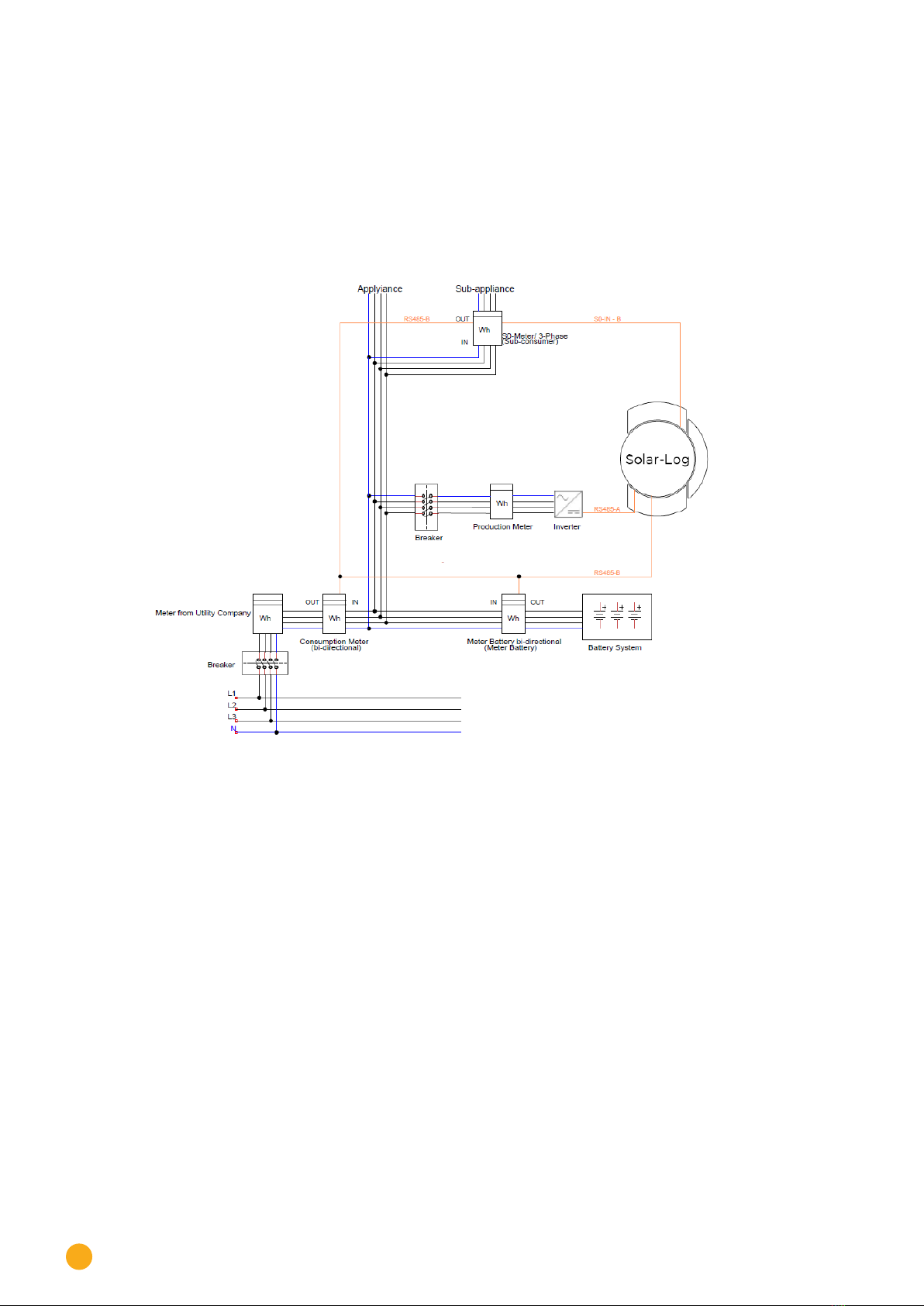
3.3.1 Meter connection options to record the total consumption via an
RS485/S0 interface.
This meter has to measure the total consumption of the house.
The meters installed by grid operators, or two-way meters, cannot be used to implement
this function.
Fig.: Wiring diagram to record self-consumption. (optional with battery storage)
8
General Information on Wiring
Wiring meters to record self-consumption
3.3.2 Meter connection options for bi-directional recording of the total con-
sumption via only an RS485 interface.
If there is feed-in in a sub-distribution, the option mentioned above can be used. In this
case, the the amount of feed-in power and power obtained from the grid can be recorded with a bi-direc-
tional meter. With this,
the Solar-Log™ can calculate the consumption.
Fig.: Wiring diagram for recording self-consumption – bi-directional meter. (optional with battery storage)

9
Solar-Log™ PRO380 Mod
Solar-Log™ PRO380 Mod
4 Solar-Log™ PRO380 Mod
4.1 Solar-Log™ PRO380 Mod
Selections available under Solar-Log Pro
Overview
• The communication address has to be assigned.
• 2-pin wiring
• Installation steps
• Switch off the meter and the Solar-Log™.
• Connect the meter to the Solar-Log™.
Note
The communication address is set to 1 by default, but can be adjusted if several meters are
connected to one RS485 bus. Maximum of 32 meters per RS485 bus
Connect the meter to the Solar-Log™.
The wiring is done using a
• self-made cable connection with a terminal block connector.
4.1.1 Connection diagram
according to circuit type 1000 (DIN 43856)
Input "L1, L2, L3" Supply line input phase "L1, L2, L3"
Output "L1, L2, L3" Supply line output phase "L1, L2, L3"
Terminal "N" Neutral conductor connection "N"
Terminal 18, 19 Sopulse output "consumption" (terminal 18 = "+")
Terminal 20, 21 Sopulse output "supply" (terminal 20 = "+")
Terminal 22, 23 ModBus connection terminal 22 -> A, 23 -> B
Terminal 24, 25 External tariff switching (230V AC)
The SO signal for the supply is not used when a meter
is connected to the Solar-Log™.

10
Solar-Log™ PRO380 Mod
Solar-Log™ PRO380 Mod
Connection diagram for different operating modes
The meter connections are labeled IN (bottom) and OUT (top).
Solar-Log™ Pro380 Mod (RS485 or S0) connection assignments
►As consumption or sub-consumer meter Connection to the grid (IN) – connection for appli-
ances (OUT)
►As inverter / production meter Connection for the production (IN) – connection to
the grid (OUT)
Solar-Log™ Pro380 Mod connection assignments (only RS485)
►As a consumption meter (bi-directional) Connection for grid (OUT) – connection to the
house/plant (IN)
(installation position according to the arrow system)
►As battery meter (bi-directional): Connection to the production/grid (IN) – connection
to the battery (OUT)
Cable connection via RS485:
Solar-Log™ terminal strip connector Solar-Log™ PRO380 Mod
Terminal PIN
►1 22 (A)
►4 23 (B)
Note
If the meter is the last device on the bus, it has to be terminated at connection block 22 and 23
with a resistor (120 ohm / 0.25W).
Note
The Solar-Log™ PRO380 Mod cannot be connected to the inverters with a single bus.
For this reason, use one RS485 connection for the inverters and one RS485 connection for the
Solar-Log™ PRO380 Mod.
►A combination with an M&T Sensor on the same bus is possible.
Possible meter operating modes for the Solar-Log™ PRO380 Mod via RS485:
• Battery (Bi-directional meter)
• Meter for the entire plant
• Sub-consumption meter
• Consumption meter
• Battery (Bi-directional meter)
• Inverter mode

11
Solar-Log™ PRO380 Mod
Solar-Log™ PRO380 Mod
Cable connection via S0 (consumption):
Solar-Log™ S0terminal block Solar-Log™ PRO380 Mod
Pin assignment Pin assignment
1 - S0+ 18 - S0+
2 - S0- 19 - S0-
3
4
Place a cable bridge between pin 3 and 4 on the Solar-Log™.
Possible meter operating modes for the Solar-Log™ PRO380 Mod via SO connection (consumption):
• Meter for the entire plant
• Sub-consumption meter
• Consumption meter
• Inverter mode

12
Inepro
Inepro 1250D
5 Inepro
5.1 Inepro 1250D
Selections available under Inepro / DMM
Overview
• The communication address cannot be freely assigned.
• 2-pin wiring
• Installation steps
• Switch off the meter and the Solar-Log™.
• Connect the meter to the Solar-Log™.
Connect the meter to the Solar-Log™.
The wiring is done using a
• self-made cable connection with a terminal block connector.
Cable connection via RS485:
Solar-Log™ RS485 terminal block Inepro 1250D
Pin assignment Pin assignment
111 - RS485A
410 - RS485B
Possible meter operating modes for the Inepro meter 1250D via RS485:
• Meter for the entire plant
• Sub-consumption meter
• Consumption meter
• Inverter mode
Cable connection via S0:
Solar-Log™ S0terminal block Inepro 1250D
Pin assignment Pin assignment
1 - S0+ 9 - S0+
2 - S0- 8 - S0-
3
4
Place a cable bridge between pin 3 and 4 on the Solar-Log™.
Possible meter operating modes for the Inepro 1250D meter via S0:
• Meter for the entire plant
• Sub-consumption meter
• Consumption meter
• Inverter mode
13
Inepro
Inepro 1250D
5.1.1 Connection diagram for dierent operating modes
Solar-Log™ Inepro 1250D (RS485 or S0) connection assignments
►As consumption or sub-consumer meter Connection to the grid (IN) – connection for appli-
ances (OUT)
►As inverter / production meter Connection for the production (IN) – connection to
the grid (OUT)
Note
The Inepro 1250D cannot be used on the same bus input with RS422 connected inverters.
Note
All three phases have to be connected for the Solar-Log™ to accurately detect the meter.
If an Inepro 1250D is used, the PRG button on the meter must be pressed and held down during
entire detection process.
If it is not possible to hold down the PRG button during the whole process, we recommend
provisionally connecting the meter to the Solar-Log™ with a short cable after the installation in
order to be able to press and hold down
the PRG button during entire detection process.
In a second detection attempt with the inverter, the meter is then detected by the Solar-Log™
even if the PRG button is not pressed.
The detection of an Inepro 1250D in an existing installation can take up to 15 minutes. After the
detection, a restructuring of the data takes places which can take up to 45 minutes depending
on the amount of data on the devices.
Note
The Inepro 1250D meters are automatically assigned the mod bus address 234 by Solar-Log™
during the detection process.
This address is therefore not allowed to be used for other devices.
After the configuration, the display on the Inepro meter alternates between the meter status
and the address display (ID=EA). This can be used to check if Solar-Log™ has correctly detected
the meter.
►AllRS485metershavetobeterminatedwitha120Ωresistorbetweenthetwopinsused.

14
Inepro
Inepro 75D
5.2 Inepro 75D
Selections available under Inepro / DMM
Overview
• The communication address cannot be freely assigned.
• 2-pin wiring
• Installation steps
• Switch off the meter and the Solar-Log™.
• Connect the meter to the Solar-Log™.
Connect the meter to the Solar-Log™.
The wiring is done using a
• self-made cable connection with a terminal block connector.
Cable connection via RS485:
Solar-Log™ RS485 terminal block Inepro 75D
Pin assignment Pin assignment
1 8 - RS485A
4 7 - RS485B
Possible meter operating modes for the Inepro 75D meter via RS485:
• Meter for the entire plant
• Sub-consumption meter
• Consumption meter
• Inverter mode
Cable connection via S0:
Solar-Log™ S0terminal block Inepro 75D
Pin assignment Pin assignment
1 - S0+ 6 - S0+
2 - S0- 5 - S0-
3
4
Place a cable bridge between pin 3 and 4 on the Solar-Log™.
Possible meter operating modes for the Inepro 75D meter via S0:
• Meter for the entire plant
• Sub-consumption meter
• Consumption meter
• Inverter mode

15
Inepro
Inepro 75D
Note
The Inepro 75D cannot be used on the same bus input with RS422 connected inverters.
Note
The Inepro 75D meters are automatically assigned the mod bus address 234 by Solar-Log™
during the detection process.
This address is therefore not allowed to be used for other devices.
After the configuration, the display on the Inepro meter alternates between the meter sta-
tus and the address display (ID=EA). This can be used to check if Solar-Log™ has correctly
detected the meter.

16
Iskra
Iskra WS0021
6 Iskra
6.1 Iskra WS0021
Selections available under Iskra
Overview
• 2-pin wiring
• Installation steps
• Switch off the meter and the Solar-Log™.
• Connect the meter to the Solar-Log™.
Connect the meter to the Solar-Log™.
The wiring is done using a
• self-made cable connection with a terminal block connector.
Cable connection via S0:
Solar-Log™ S0terminal block Iskra WS0021
Pin assignment Pin assignment
1 - S0+ 9 - S0+
2 - S0- 8 - S0-
3
4
Place a cable bridge between pin 3 and 4 on the Solar-Log™.
Possible meter operating modes for the Iskra WS0021 meter via S0:
• Meter for the entire plant
• Sub-consumption meter
• Consumption meter
• Inverter mode

17
Iskra
Iskra WS0031
6.2 Iskra WS0031
Selections available under Iskra
Overview
• 2-pin wiring
• Installation steps
• Switch off the meter and the Solar-Log™.
• Connect the meter to the Solar-Log™.
Connect the meter to the Solar-Log™.
The wiring is done using a
• self-made cable connection with a terminal block connector.
Cable connection via S0:
Solar-Log™ S0terminal block Iskra WS0031
Pin assignment Pin assignment
1 - S0+ S0+
2 - S0- S0-
3
4
Place a cable bridge between pin 3 and 4 on the Solar-Log™.
Possible meter operating modes for the Iskra WS0031 meter via S0:
• Meter for the entire plant
• Sub-consumption meter
• Consumption meter
• Inverter mode

18
Janitza UMG 104 (Utility Meter)
Janitza UMG 104
7 Janitza UMG 104 (Utility Meter)
7.1 Janitza UMG 104
The Solar-Log™ Utility Meter is a universal metering device. It can be integrated in both low- and medium-
voltage networks (via a transformer) and is needed for various functions:
• controlling voltage-dependent reactive power via the Q(U) function
• controlling reactive power at the feeding point
• recording the measurement data needed for the response signals sent to the grid operator
Only voltage measurements are required for voltage-dependent reactive power reduction Q(U). However,
we still recommend using both current and voltage measurements to be able to check that the reduction
function is operating properly. Current and voltage measurements are needed for the other functions.
Utility Meter supply voltage:
• 95-240Vac, 45-65Hz or 135-340Vdc
The Utility Meter's measuring inputs have the following limits:
• Voltage line conductor AC (without a voltage transformer): 10…300 V AC
• Voltage phase AC (without a voltage transformer): 17…520 V AC
• Current (without a current transformer) 0.005, 7.5 A
• Frequency of the fundamental component: 45 ..65 Hz
The limit may not be exceeded. For this reason, a measuring transformer needs to be installed for most
applications.
We recommend the following transformer ratio:
• Voltage: Secondary 100V
e.g. at 20kV grid converter 20000:100V
• Current: Secondary 5A
e.g. 100:5A
Note
The Utility Meter that we use is produced by the company Janitza.
Refer to the Janitza UMG 104 manual for further technical details.
We cannot guarantee the functionality of other Janitza devices.
►The operating modes Utility Meter (U / U+I) is only possible with the Solar-Log 1000 and
2000.
Note
The Utility Meter cannot be connected to the inverters with a single bus.
For this reason, use one RS485 connection for the inverters and one RS485 connection for the
Utility Meter.

19
Janitza UMG 104 (Utility Meter)
Janitza UMG 104
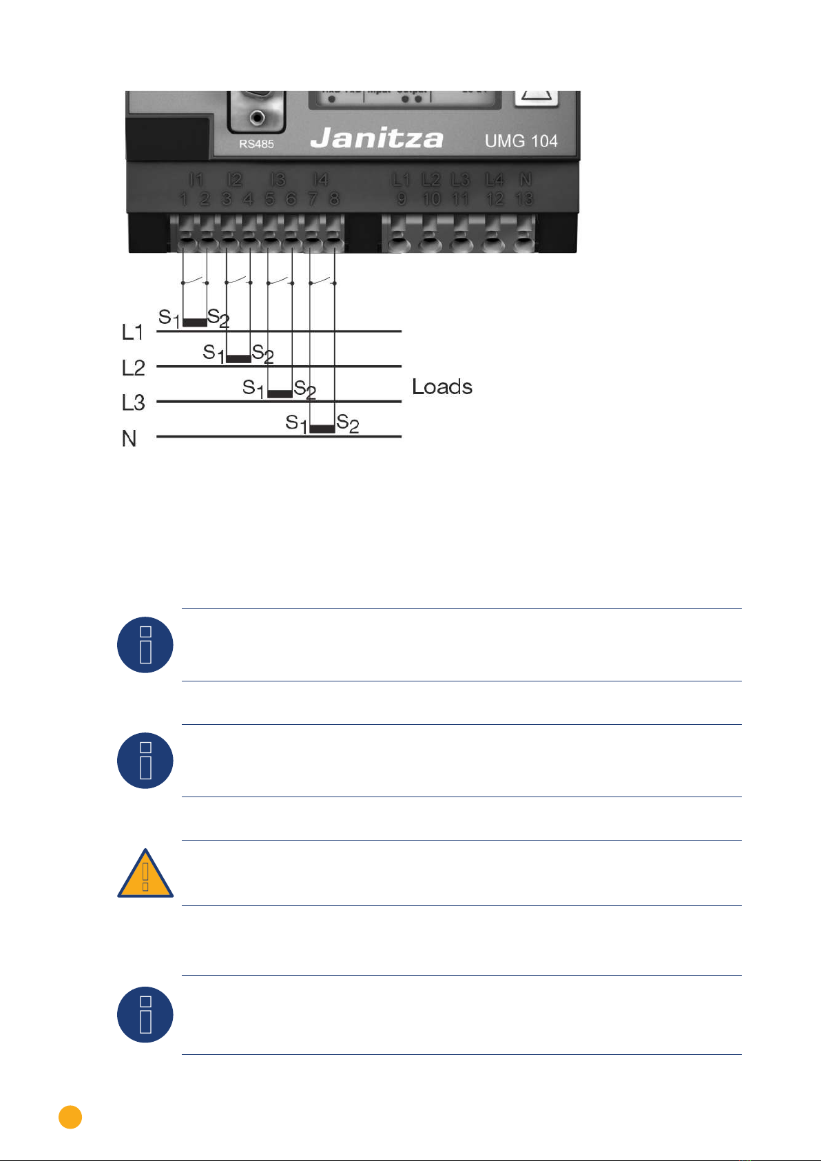
Connecting the Utility Meter to the power grid
Fig.: Utility Meter connection diagram for voltage measurements in low-voltage power grids
Fig.: Utility Meter connection diagram for voltage measurements with current transformers (medium volt-
age)
20
Janitza UMG 104 (Utility Meter)
Janitza UMG 104
Fig.: Utility Meter connection diagram for current measurements with current transformers
Procedure
• Enter the supply voltage into the Utility Meter
Note
We recommend using a fuse to safeguard the connection lines for the supply voltage. Please
follow the instructions in the Janitza UMG 104 manual.
Note
Supply voltages that do not correspond to the specifications on the rating plate can cause mal-
functions and damage the device.
Caution
The inputs for the supply voltage are dangerous to touch.
Note
The measurement voltage must in effect be at least 10V or an exact measurement is not possi-
ble.
Other manuals for 300
1
This manual suits for next models
6
Table of contents
Other Solar-Log Measuring Instrument manuals

Solar-Log
Solar-Log PRO1 User manual

Solar-Log
Solar-Log PRO2 User manual

Solar-Log
Solar-Log PRO380 User manual

Solar-Log
Solar-Log PRO380 User manual

Solar-Log
Solar-Log Pro 380 User manual

Solar-Log
Solar-Log 200 User manual

Solar-Log
Solar-Log 2000 User manual

Solar-Log
Solar-Log PRO380-CT User manual

Solar-Log
Solar-Log PRO380 User manual

Solar-Log
Solar-Log 350 User manual


