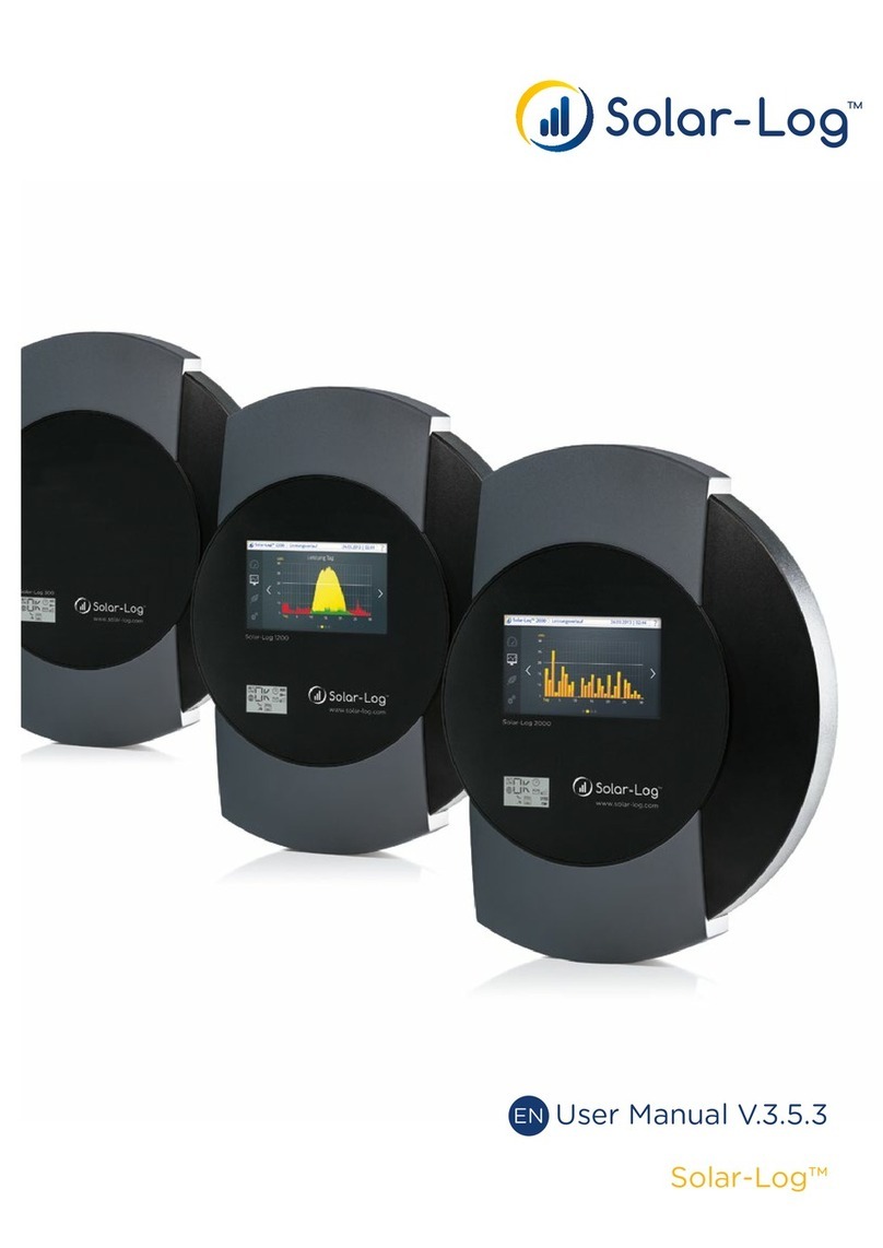
Solar-Log 350 User manual

Installation Manual
Solar-Log® Socket Meter
Installation Manual
Solar-Log® Socket Meter

2
Table of Contents
Getting Started 4
Required hardware 4
Before you begin 4
Installation Guide 5
Safety Precautions 5
Meter Installation 6
Solar-Log 350 (and Solar-Log 350 LAN) 7
Wiring Diagram 8
Step by Step 9
Solar-Log 360 10
Wiring Diagram 11
Step by Step 12
Solar-Log 370 13
Wiring Diagram 14
Optional Connections to External Devices 15
Step by Step 16
Device Detection 18
Conrm Cellular Connection When Using LAN Communication 19

3
Solar-Log® Socket Meter LCD Status 20
Troubleshooting 21
Solar-Log® WEB Registration (Before or After Installation) 22
Warranty 24
Technical Support
For additional support please visit www.solar-log-america.com under the Service &
Support tab, and our experts will provide answers to any questions concerning Solar-Log®
products or call our technical support team at (203) 702-7189.
Online Support
www.t-mobile.com/coverage.html
www.att.com/maps/wireless-coverage
www.solar-log-america.com/service-support

4
Getting Started
Required Hardware
• 2S socket meter base - 240/120V single phase (not included)
Before You Begin
Check electrical specification
• 240/120V single phase
• Max plant size 48 kW (200 A)
Check cellular coverage depending on installed SIM card
• Onsite with cellphone – must have 2 bars of signal showing GPRS/E/3G/4G or LTE
• T-Mobile: offsite at www.t-mobile.com/coverage.html
• AT&T: offsite at www.att.com/maps/wireless-coverage
If cellular coverage is not available, please use Solar-Log 350 LAN (Part No. 823210) or
Solar-Log 370 (Part No. 225852) and connect to an internet router via Ethernet.

5
Installation Guide
Safety Precautions
DANGER! Lethal voltage inside the meter!
Thoroughly read and understand this guide before installing and operating
the unit.
Follow all instructions and safety precautions in this guide.
Prior to performing any work turn off all power supplying the equipment in which the
meter is to be installed.
Only qualied personnel should work on the meter and should be familiar with the technol-
ogy and the hazards associated with electrical equipment.
Beware of potential hazards and wear personal protective equipment.
Only connect the meter as described in this manual.
Hazardous voltages can cause shock, burns or death. To prevent exposure to hazardous
voltages, disconnect and lock out all power sources before servicing and removing com-
ponents.
Modications made to the product may void the warranty.
All work must be done in accordance to state and local code and safety practices.
Never work alone and before performing any tests, installation or maintenance on this equipment, isolate or dis-
connect all hazardous live circuits and sources of electric power. Assume that all circuits are live until they have
been completely de-energized, tested, and tagged. Pay particular attention to the design of the power system.
Consider all sources of power, including the possibility of back feed.

6
Meter Installation
Warning: The Solar-Log® Socket Meter contains lethal voltages. The meter
should never be disassembled. Failure to observe this practice can result
in serious injury or death. Do not interchange base and electronics module
assemblies between meters. Calibration data stored in meter is particular to a matched
base assembly and electronics module. Interchanging these components causes the meter
to lose calibration.
The meter is plugged into a single phase, 3 wire, 2S meter socket using standard meter
installation practices. The meter base has current and potential terminals extending out-
side from the back of the meter. These terminals engage with the socket jaws, which are
connected to the service lines. The socket jaws provide heavy contact force with the help
of spring.
Refer to page 7 for installing a Solar-Log 350 (or Solar-Log 350 LAN)
Refer to page 10 for installing a Solar-Log 360
Refer to page 13 for installing a Solar-Log 370

7
Solar-Log 350 (and Solar-Log 350 LAN)
The Solar-Log 350 is a universal monitoring device for PV production and reporting. This
easy to install device is compatible with all residential solar PV inverters and does not
require on-site con guration.

8
Wiring Diagram
Notice: The wiring diagram includes rudimentary connection diagrams and is not intended
as an installation guide. The diagrams are shown for informational purposes only.
*Internet Router is not provided
**Solar-Log 350 LAN is only recommended when cellular service is weak or unavailable onsite.

9
Step by Step
Step 1
Switch main breaker OFF
in distribution panel and
ensure all other voltage
sources are off.
Step 2
Install socket & electrical
wiring according to local
and national electric code
Step 3
Plug Solar-Log 350 & GE
Meter into socket and re-
place cover
Step 4
Switch main breaker ON in
distribution panel
Step 5
Check meter LCD display to
verify line voltage & power.
See pg 20.
Step 6
Check LEDs (located at
bottom)
Flashing Green (for Solar-Log 350)
Waiting for cellular connection
Solid Green (for Solar-Log 350)
Using Cellular Connection
Green with Quick Blink Every 5
Seconds (for Solar-Log 350 LAN)
Using LAN Connection
Other LEDs
See Troubleshooting

10
Solar-Log 360
The Solar-Log 360 is a universal monitoring device for PV production and home consump-
tion. This easy to install device is compatible with all residential solar PV inverters and
does not require on-site con guration. Included with the Solar-Log 360 is a Solar-Log 10
(bi-directional meter) and 2 current transducers (CTs) for measuring home consumption.
The Solar-Log 360 is a universal monitoring device for PV production and home consump-

11
Wiring Diagram
Notice: The wiring diagram includes rudimentary connection diagrams and is not intended
as an installation guide. The diagrams are shown for informational purposes only.

12
Step by Step
Step 1
Switch main breaker OFF in
distribution panel and ensure
all other voltage sources are
off.
Step 2
Install socket & electrical
wiring according to local and
national electric code
Step 3
Install SL 10 (bi-directional
consumption meter) nearby
distribution panel according
to SL10 manual (1. install CTs
- check arrows for correct
energy ow! 2. do voltage
tapping, 3. wire RS485)
Step 4
Plug Solar-Log 360 & GE
Meter into socket and re-
place cover
Step 5
Switch main breaker ON in
distribution panel
Step 6
Check meter LCD display to
verify line voltage & power.
See pg 20.
Step 7
Check LEDs (located at
bottom)
Flashing Green
Waiting for cellular connection
Flashing Yellow
Searching for SL10 device
Solid Green
Finished
Other LEDs
See Troubleshooting

13
Solar-Log 370
The Solar-Log 370 is a universal monitoring device for PV production and reporting with
numerous connectivity options. This device is compatible with all residential solar PV
inverters with easy on-site installation. The Solar-Log 370 comes with an LAN cable for
internet connection and 2 x RS485 ports for inverter direct monitoring, weather station,
consumption monitoring, and power management.
The Solar-Log 370 is a universal monitoring device for PV production and reporting with

14
Wiring Diagram (not for inverter direct monitoring)
Notice: The wiring diagram includes rudimentary connection diagrams and is not intended
as an installation guide. The diagrams are shown for informational purposes only.

15
Optional Connections to External Devices including Inverter Direct
*120V outlet and power supply required for weather sensor. Power supply sold separately
(part number 869203).
**Some inverter brands require direct monitoring via LAN connection. Consult the
Solar-Log 370 Inverter Installation Appendix at www.solar-log-america.com/devices.

16
Step by Step
Step 1
Switch main breaker OFF
in distribution panel and
ensure all other voltage
sources are off.
Step 2
Install socket & electrical
wiring according to and
national electric code
Step 3 (optional)
If connecting to external
devices, complete the wiring
according to their manuals.
Refer to the Device Installa-
tion Manual on our website.
Step 4
Plug Solar-Log 370 & GE
Meter into socket and re-
place cover
Step 5
Switch main breaker ON in
distribution panel.
Step 6
Check meter LCD display to
verify line voltage & power.
See pg 20.
Inverter must be on and
producing for diagnostics.
!

17
Step 7
Check LEDs (located at
bottom)
Flashing Green
Waiting for internet connection
Flashing Yellow
Searching for external devices
Solid Green
Using Cellular Connection
Green with Quick Blink Once Every
5 Seconds
Using LAN Connection
Other LEDs
See Troubleshooting

18
Device Detection
All external device conguration is done on the device detection page. Refer to the Device
Installation Manual on our website for instructions on wiring your external device. The
Solar-Log® Serial Number and EasyCode can be found on the back of the meter and manu-
al. Have this information available for conguration.
Step 1
Visit our device detection page http://sl370.solarlog-web.net and log-in.
Step 2
Click on ‘add new device’ and add all external devices like inverter, consumption meter
(Solar-Log 10), or weather station accordingly. Press SAVE.
Step 3
Once all external devices have been entered click on ‘start device detection’. It takes until
the next data communication interval for the results to be visible.
Step 4
If all devices have not been detected check the wiring and click restart device detection.

19
Confirm Cellular Connection When Using LAN Communication
If the meter is connected to an internet router it will connect via Ethernet and the green
LED will ash once every 5 seconds. To conrm that cellular service is also working as a
backup for data transfer:
• Disconnect the LAN cable from the router
• Watch the green LED light to change to a solid green light indicating that the meter is
now connected via cellular network. This process can take up to 15 minutes.
• If no cell service is available a solid red light appears instead.
• Once cell service is checked again reconnect the LAN cable to the router to resume
Ethernet connection. The green LED will ash once every 5 seconds indicating LAN
connection.

20
Solar-Log® Socket Meter LCD Status
Launch Device
On powering up the meter, verify meter operations by observing the LCD display
• For the rst 5 seconds, the LCD will display an All Segment Test (all display items
shown).
• LCD displays 5 digits for kWh as well as alternating volts and kW.
If the meter displays “Ser” error in the lower-left display section, it implies that the meter
has been connected in a 12S/25S socket or to 3 phase service. Please conrm that the
meter is connected correctly in a 2S socket.
For all other issues or error messages please contact Solar-Log®Support at (203) 702-7189
This manual suits for next models
1
Table of contents
Other Solar-Log Measuring Instrument manuals
Solar-Log
Solar-Log PRO380-Mod-CT User manual
Solar-Log
Solar-Log PRO1 User manual
Solar-Log
Solar-Log 2000 User manual

Solar-Log
Solar-Log PRO380-CT User manual
Solar-Log
Solar-Log 300 User manual
Solar-Log
Solar-Log PRO380-CT User manual
Solar-Log
Solar-Log PRO1 User manual
Solar-Log
Solar-Log PRO380 User manual
Solar-Log
Solar-Log Pro 380 User manual
Solar-Log
Solar-Log 200 User manual
