manuals.online logo
Brands
  1. Home
  2. •
  3. Brands
  4. •
  5. Soler & Palau
  6. •
  7. Fan
  8. •
  9. Soler & Palau Breidert Air Products JencoFan FF50 User manual

Soler & Palau Breidert Air Products JencoFan FF50 User manual

ïîð ÊßÝ Ô×ÒÛ ×Ò
ÞÔßÝÕ
ÞÔßÝÕ ÙÎÑËÒÜ
ÉØ×ÌÛ ÌÑ
ÉØ×ÌÛ
ÍÉ×ÌÝØ ÑÎ Ì×ÓÛÎ
ÙÎÛÛÒ ÌÑ
ÙÎÛÛÒ ÑÎ
ÞßÎÛ É×ÎÛ
ÍÉ×ÌÝØ ÞÑÈ
ÎÛÝÛÐÌßÝÔÛ
ÉØ×ÌÛ ÌÑ
ÉØ×ÌÛ
ÞÔßÝÕ ÌÑ
ÞÔßÝÕ
WARNING
TO REDUCE THE RISK OF FIRE, ELECTRIC SHOCK, OR INJURY TO PERSONS,
OBSERVE THE FOLLOWING:
1. Use this unit only in the manner intended by the manufacturer. If you have questions,
contact the manufacturer at the address or telephone number listed in the warranty.
2. Before servicing or cleaning unit, switch power off at service panel and lock the
service disconnecting means to prevent power from being switched on accidentally.
When the service disconnecting means cannot be locked, securely fasten a
prominent warning device, such as a tag, to the service panel.
3. Installation work and electrical wiring must be done by a qualified person(s) in
accordance with all applicable codes and standards, including fire-rated construc-
tion codes and standards.
4. Sufficient air is needed for proper combustion and exhausting of gases through the
flue (chimney) of fuel-burning equipment to prevent backdrafting. Follow the heating
equipment manufacturer's guideline and safety standards such as those published
by the National Fire Protection Association (NFPA), and the American Society for
Heating, Refrigeration and Air Conditioning Engineers (ASHRAE), and the local
code authorities.
5. When cutting or drilling into wall or ceiling, do not damage electrical wiring and other
hidden utilities.
6. Ducted fans must always be vented to the outdoors.
7. This unit may be used over a tub or shower enclosure when installed in a GFCI
protected branch circuit.
8. If this unit is to be installed over a tub or shower, it must be marked as appropriate
for the application.
9. Never place a switch where it can be reached from a tub or shower.
10. This unit must be grounded.
CEILING EXHAUST FAN
CAUTION
1. For general ventilating use only. Do not use to exhaust hazardous or explosive
materials and vapors.
2. To avoid motor bearing damage and noisy and/or unbalanced impellers, keep
drywall spray, construction dust, etc. off power unit.
3. Please read specification label on product for further information and requirements.
MODEL FF50
(Part No. 090192101)
HOUSING
FLAP
SCREWDRIVER
SLOT
1. Remove motor plate from housing by pushing down on rib in plate while pulling out
on side of housing. Motor plate may also be removed by inserting a straight-blade
screwdriver into slot in housing and twisting screwdriver.
2. Remove wiring cover from housing by pulling straight out. Unit is shipped ready to
wire through the top of housing. To wire through the side, bend housing flap to cover
top hole and expose side hole. DO NOT BREAK OFF FLAP. If flap breaks, plug
unused hole using standard electrical hole plug.
WIRING
COVER
5. Use embossed measuring guides on side of housing to position housing for proper
wall or ceiling thickness. MAKE SURE HOUSING WILL BE FLUSH WITH FINISHED
CEILING OR WALL. Nail housing or stude joist using four nails to ensure a solid,
quiet installaltion.
3. Turn off electrical power at service entrance and connect power cable to housing
using appropriate connector. Wire black to black, white to white, and green to green
or bare wire. Push all wiring up into corner of unit and replace wiring cover. Make sure
cover holds housing flap in place against side or top of housing. CAUTION: DO NOT
ALLOW WIRES TO EXTEND OUTSIDE OF WIRING BOX. Wire left exposed will
become pinched or cut when motor plate is installed. Electrical shock may
result.
4. Choose the location for your fan. For best performance, use the shortest possible
duct run and a minimum number of elbows. For wall installations: Position unit so
damper flap closes when unit is off.
INSTALLATION
USE AND CARE
DISCONNECT ELECTRIC POWER SUPPLY AND LOCK OUT SERVICE PANEL BE-
FORE SERVICING THE UNIT.
PREVENTATIVE MAINTENANCE
A clean fan provides better service. Disconnect the power supply and clean the fan as
described below:
TO CLEAN GRILLE - Use a mild detergent, such as dishwashing ligquid, and dry with
a soft cloth. DO NOT USE ABRASIVE CLOTHS, STEEL WOOL PADS, OR SCOUR-
ING POWDERS.
TO CLEAN FAN ASSEMBLY - Unplug motor cord from receptacle. To remove motor
plate: Find the single tab on the motor plate (located next to the receptacle). Push up
near motor plate tab while pushing out on side of housing. Or insert a straight-blade
screwdriver into slot in housing (next to tab) and twist screwdriver. Gently vacuum fan,
motor and interior of housing. METAL AND ELECTRICAL PARTS SHOULD NEVER
BE IMMERSED IN WATER.
TO REASSEMBLE ALL ABOVE PARTS - Reverse all procedures explained above.
MAINTENANCE
The motor is permanently lubricated and never needs oiling. If the motor bearings are
making excessive or unusual noises, replace the motor with the exact service motor.
You should replace the impeller at the same time.
SOLER & PALAU
BREIDERT AIR PRODUCTS
JENCOFAN
READ AND SAVE THESE INSTRUCTIONS
99042813E
KEY
NO. PART NO. DESCRIPTION
1 99110752 Grille Only
2 99140137 Grille Springs (2 Required)
97009346 Grille Assembly (Includes Key
Nos. 1 & 2)
3 99080254 Motor
4 98006791 Motor Plate
5 99110655 Blower Wheel
6 99260428 Nut #6-32 (2 Required)
7 97016377 Damper/Duct Connector
8 99271252 Receptacle
9 98006773 Wiring Cover
10 97008319 Housing Assembly
Order replacement parts by part number - not key
number.
SERVICE PARTS
6. Install 3" round duct onto damper/duct connector. If rigid ductwork
is used, its seam should be positioned at top of damper/duct
connector. Tape the joint and extend ducting to a wall cap or roof
cap. Make sure the damper operates freely. Ceiling or wall can now
be finished.
8. Squeeze grille springs together and insert springs into slots
in motor plate. Push grille up against ceiling or wall.
1
2
6
35
10
9
8
7
4
7. Replace the motor plate removed in Step 1. Insert two motor plate
tabs into slots in housing and then pivot motor plate up until third
tab on plate snaps into matching slot in housing. Make sure tabs
hold motor plate securely in place. Plug in motor.
NOTE: If damper detaches from duct connector, re-insert it by
squeezing duct connector top-to-bottom while guiding posts
on damper flap into holders in duct connector. The horizontal
rib should be on the outside surface of damper flap and
damper flap should move freely inside of duct connector.
ONE YEAR LIMITED WARRANTY
Soler & Palau Breidert Air Products JencoFan, warrants all products to be free from defects in material or workmanship for a period of one year from date of shipment. If it
appears within one year from date of shipment by the Company to the original purchaser that any such ventilator or the material used therein does not meet the warranties
specified above and the purchaser notifies the Company promptly, the Company agrees to remedy any such defect, at the companys option.
This warranty shall not apply to any equipment which has been repaired or altered in any way so as, in the companys judgement, to affect its performance or reliability, nor
which has been improperly installed or subjected to misuse, negligence, or accident. Neither shall this warranty apply to labor to remove or install defective parts, profits lost
due to failure of the ventilator or electric motors or belts. Electric motors, however, carry the warranty of the motor manufacturer.
This warranty is expressly in lieu of all other warranties expressed or implied, and of all other obligations or liabilities on the companys part. The company neither assumes,
nor authorizes any representative or other persons to assume for it, any other liability in connection with the sale of its equipment.
Soler & Palau
Breidert Air Products
JencoFan
6393 Powers Ave
Jacksonville, FL 32217
CEILING VENTILATOR/VENTILATEUR DE PLAFOND
MODEL/MODÈLE FF80
WARNING
TO REDUCE THE RISK OF FIRE, ELECTRIC SHOCK, OR
INJURY TO PERSONS, OBSERVE THE FOLLOWING:
1. Use this unit only in the manner intended by the manufac-
turer. If you have questions, contact the manufacturer at
the address or telephone number listed in the warranty.
2. Before servicing or cleaning unit, switch power off at ser-
vice panel and lock the service disconnecting meansto pre-
vent power from being switched on accidentally. When the
service disconnecting means cannot be locked, securely
fasten a prominent warning device, such as a tag, to the
service panel.
3. Installation work and electrical wiring must be done by a
qualified person(s) in accordance with all applicable codes
and standards, including fire-rated construction codes and
standards.
4. Sufficient air isneeded for proper combustion and exhaust-
ing of gases throughthe flue(chimney)of fuelburning equip-
ment to prevent backdrafting. Follow the heating equipment
manufacturer’s guideline and safety standards such as
those published by the National Fire ProtectionAssociation
(NFPA), and the American Society for Heating, Refrigera-
tion and Air Conditioning Engineers (ASHRAE), and the
local code authorities.
5. When cutting or drilling into wall or ceiling, do not damage
electrical wiring and other hidden utilities.
6. Ducted fans must always be vented to the outdoors.
7. If this unit is to be installed over a tub or shower, it must be
marked as appropriate for the application and be connected
to a GFCI (Ground Fault Circuit Interrupter) - protected
branch circuit.
8. Never place aswitch where itcan be reachedfrom a tub or
shower.
9. This unit must be grounded.
CAUTION
1. For general ventilating use only. Do not use to exhaust haz-
ardous or explosive materials and vapors.
2. To avoid motor bearing damage and noisy and/or unbal-
anced impellers, keep drywall spray, construction dust, etc.
off power unit.
3. Please read specification label on product for further infor-
mation and requirements.
TYPICAL INSTALLATIONS
*
READ AND SAVE THESE
INSTRUCTIONS
ÿ
Installer: Leave this manual with the
homeowner.
Homeowner: Use and Care information
on page 4.
*Additional framing must be a 2x6 (minimum height), at
least 9-inches long.
LISEZ ET CONSERVEZ
CES DIRECTIVES
AVERTISSEMENT
AFIN DE DIMINUER LES RISQUES DINCENDIE,
DÉLECTROCUTION OU DE BLESSURES, SUIVEZ CES
DIRECTIVES :
1. N’utilisez cet appareil que de la manière prévue par le
manufacturier. Pour toute question, adressez-vous à lui à
l’adresse ou au numéro de téléphone indiqués dans la
garantie.
2. Avant d’effectuer toute réparation ou nettoyage, coupez
le courant au panneau électrique et verrouillez le
disjoncteur afin d’éviter que le courant ne soit rétabli
accidentellement. Si le disjoncteur ne peut être verrouillé,
accrochez une affiche ou une étiquette bien en vue sur le
panneau.
3. L’installation et les branchements électriques doivent être
effectués par un personnel compétent, conformément aux
normes et aux codes en vigueur, y compris les normes et
les codes du bâtiment relatifs à la résistance au feu.
4. Assurez un apport d’air suffisant par un conduit de
cheminée pour la combustion et l’évacuation adéquates
des gaz de tout appareil à combustion d’huile afin de
prévenir tout refoulement des gaz, conformément aux di-
rectives du fabricant et aux consignes de sécurité publiées
par des organismes tels que la National Fire Protection
Association (NFPA), l’American Society for Heating, Re-
frigeration and Air Conditioning Engineers (ASHRAE), et
les autorités locales.
5. Lors du perçage ou du découpage d’un mur ou d’un
plafond, prenez garde de ne pas endommager le câblage
électrique ni aucune installation dissimulée.6. La sortie
de tout conduit d’évacuation de ventilateur doit aboutir à
l’extérieur.
7. Si cet appareil doit être installé au-dessus d’une baignoire
ou d’une douche, il doit comporter les mentions
appropriées pour ces utilisations et être connecté à un
circuit protégé par un disjoncteur de fuite à la terre (GFCI).
8. Ne placez jamais un interrupteur de sorte que l’on puisse
l’atteindre d’une baignoire ou d’une douche.
9. Cet appareil doit être relié à une mise à la terre.
ATTENTION
1. Cet appareil ne convient qu’à des fins de ventilation
générale. Ne pas l’utiliser pour l’évacuation de matières
ou de vapeurs dangereuses ou explosives.
2. Pour éviter que les roulements du moteur ne soient
bruyants ou s’abîment, ou de déséquilibrer la roue à
ailettes, protégez l’appareil des poussières de placoplâtre
et de construction.
3. Veuillez lire l’étiquette des caractéristiques techniques du
produit pour de plus amples informations quant aux
exigences.
ÿ
Installateur :Veuillezlaissercemanuelau
propriétaire.
Propriétaire :Voir le mode dutilisation et
dentretien à la page 4.
*
*
ØÑËÍ×ÒÙ
ÝÛ×Ô×ÒÙ
ÖÑ×ÍÌ
ÓÑËÒÌ×ÒÙ ÌßÞÍ
ÙÎ×ÔÔÛ
ÝÛ×Ô×ÒÙ
ÓßÌÛÎ×ßÔ
ÐÑÉÛÎ ÝßÞÔÛ
HOUSING MOUNTED DIRECTLY TO JOIST
2x6 (or larger) Discharge parallel to joists.
ØÑËÍ×ÒÙ
î¨ì
ÝÛ×Ô×ÒÙ
ÖÑ×ÍÌ ±®
ÌÎËÍÍ
ÓÑËÒÌ×ÒÙ
ÌßÞÍ
ÙÎ×ÔÔÛ
ÝÛ×Ô×ÒÙ
ÓßÌÛÎ×ßÔ
ÐÑÉÛÎ ÝßÞÔÛ ßÜÜ×Ì×ÑÒßÔ
ÚÎßÓ×ÒÙ
î¨ì
ÝÛ×Ô×ÒÙ
ÖÑ×ÍÌ ±®
ÌÎËÍÍ
HOUSING MOUNTED TO 2x4 TRUSS
Requires additional framing for mounting tabs.
Discharge parallel to joists.
ØÑËÍ×ÒÙ
ÓÑËÒÌ×ÒÙ
ÌßÞÍ
ÙÎ×ÔÔÛ
ÝÛ×Ô×ÒÙ
ÓßÌÛÎ×ßÔ
ÐÑÉÛÎ ÝßÞÔÛ ßÜÜ×Ì×ÑÒßÔ
ÚÎßÓ×ÒÙ
þ×þ
ÖÑ×ÍÌ
þ×þ
ÖÑ×ÍÌ
HOUSING MOUNTED TO I JOIST
Requires additional framing for mounting tabs.
Discharge parallel to joists.
ØÑËÍ×ÒÙ
ÝÛ×Ô×ÒÙ
ÖÑ×ÍÌ
ÓÑËÒÌ×ÒÙ ÌßÞÍ
ÙÎ×ÔÔÛ
ÝÛ×Ô×ÒÙ
ÓßÌÛÎ×ßÔ
ÐÑÉÛÎ ÝßÞÔÛ
ìþ ÎÑËÒÜ
ÜËÝÌ
ßÜÜ×Ì×ÑÒßÔ
ÚÎßÓ×ÒÙ
HOUSING MOUNTED TO ADDITIONAL FRAMING
Discharge 900to joists.
*
ØÑËÍ×ÒÙ
î¨ì
ÝÛ×Ô×ÒÙ
ÖÑ×ÍÌ ±®
ÌÎËÍÍ
ÓÑËÒÌ×ÒÙ ÌßÞÍ
ÙÎ×ÔÔÛ
ÝÛ×Ô×ÒÙ
ÓßÌÛÎ×ßÔ
ÐÑÉÛÎ ÝßÞÔÛ
ìþ ÎÑËÒÜ
ÜËÝÌ
ßÜÜ×Ì×ÑÒßÔ
ÚÎßÓ×ÒÙ
î¨ì
ÝÛ×Ô×ÒÙ
ÖÑ×ÍÌ ±®
ÌÎËÍÍ
HOUSING MOUNTED TO 2x4 TRUSS
Requires additional framing for mounting tabs.
Discharge 900to joists.
ØÑËÍ×ÒÙ
ÓÑËÒÌ×ÒÙ ÌßÞÍ
ÙÎ×ÔÔÛ
ÝÛ×Ô×ÒÙ
ÓßÌÛÎ×ßÔ
ÐÑÉÛÎ ÝßÞÔÛ
ìþ ÎÑËÒÜ
ÜËÝÌ
ßÜÜ×Ì×ÑÒßÔ
ÚÎßÓ×ÒÙ þ×þ
ÖÑ×ÍÌ
þ×þ
ÖÑ×ÍÌ
HOUSING MOUNTED TO I JOIST
Requires additional framing for mounting tabs.
Discharge 900to joists.
*
SOLER & PALAU
BREIDERT AIR PRODUCTS
JENCOFAN
TYPICAL INSTALLATIONS
SUSPENDED CEILINGS
Housing hung with wires - 3-point mount.
INSTALLATION TYPE
*Cadrage supplémentaire en 2x6 (minimum), d’au moins
23 cm (9 po) de long.
INSTALL THE HOUSING
- PLEASE NOTE -
THE FOLLOWINGINSTALLATION ILLUSTRATIONS SHOW
2 X 6 JOISTS. IF YOU HAVE A TRUSS OR I-JOIST IN-
STALLATION, MOUNT THE VENTILATOR TO THE ADDI-
TIONAL FRAMING IN THE SAME MANNER. (Additional
framing must be a 2x6 (minimum height), at least 9-inches
long.)
New Construction
New Construction
INSTALLATION TYPE
PLAFONDS SUSPENDUS
Boîtier suspendu à des fils de fer en 3 points.
INSTALLATION DU BOÎTIER
Bâtisse en cours de construction
- VEUILLEZ NOTER -
LES ILLUSTRATIONS SUIVANTES MONTRENT UNE
INSTALLATION SUR DES SOLIVES DE 2 X 6. SI
LINSTALLATION EST FAITE SUR DES FERMES OU DES
POUTRES EN I , MONTER LE VENTILATEUR DE LA
MÊME FAÇON SUR UN CADRE. (Cadrage supplémentaire
en 2x6 (minimum), dau moins 23 cm (9 po) de long.)
1. Choose the location for your fan in the ceiling. For
best possible performance, use the shortest
possible duct run and a minimum number of
elbows.
TAB
ONGLET
HOLES
TROUS
BOTTOM EDGE OF JOIST
DESSOUS DE LA SOLIVE
3. Set housing aside and drive
nails partially into joist at the
top of both keyhole marks.
4. Hang housing from nails and
pound nails tight. To ensure
a noise-free mount, pound
another nail through the top
hole of each mounting tab.
2. Positionnez les brides de montage
contre la solive, de sorte que le bas
du boîtier soit au ras de la surface
finie du plafond.
Positionnement dans
des plafonds de 5/8, 1
et 1-1/4 po (16, 25 et 32
mm) dépaisseur :
Des trous sont marqués
dans les coins pour
différentes épaisseurs de
plafonds. Placez le
3. Mettez le boîtier de côté et enfoncez
partiellement un clou dans le haut des
marques en trous de serrure.
4. Suspendez le boîtier aux clous
puisenfoncez-les complètement. Pour
assurer un fonctionnement silencieux,
enfoncez un autre clou dans le trou
supérieur de chaque bride.
1. Choisissez l’emplacement du ventilateur au plafond. Pour
obtenir un rendement optimal, utilisez un minimum de con-
duits et de coudes.
boîtier de sorte que le dessous de la solive
soit visible dans la série de trous
correspondante. Le boîtier est alors dans la
position adéquate pour cette épaisseur de
plafond.
Positionnement dans un plafond de 1/2 po
(12 mm) dépaisseur :
Dépliez deux onglets sur les côtés du boîtier,
à 90° vers l’extérieur. Soulevez le boîtier afin
que les onglets s’appuient contre le dessous
de la solive.
Marquez le trou en forme de serrure sur chaque bride.
Additional positioning
feature for 5/8, 1, & 1-
1/4 thick ceiling
material:
Holes in corners of
housing are labeled with
various ceiling material
thicknesses. Position housing so bottom edge of
joist is visible through a matched set of holes. The
housing is now in the proper position for that
ceiling material thickness.
Additional positioning feature for 1/2 thick
ceiling material:
Bend two tabs, on side of housing,
900outward. Lift
housing until tabs contact underside of joist.
Mark the keyhole slot on both mounting brackets.
2. Position mounting brackets
against joist so that bottom
edge of housing will be
flush with finished ceiling.
2
BOÎTIER FIXÉ DIRECTEMENT AUX SOLIVES DE 2x6 (ou
plus). Sortie parallèle aux solives.
ÞÑ2Ì×ÛÎ
ÞÎ×ÜÛÍ ÜÛ
ÓÑÒÌßÙÛ
ÙÎ×ÔÔÛ
ÓßÌWÎ×ßË ÜË
ÐÔßÚÑÒÜ
Ý^ÞÔÛ ÜùßÔ×ÓÛÒÌßÌ×ÑÒ
ÍÑÔ×ÊÛ ÜË
ÐÔßÚÑÒÜ
BOÎTIER FIXÉ AUX FERMES DE 2x4 Les brides de
montage exigent un cadre supplémentaire. Sortie
parallèle aux solives.
BOÎTIER FIXÉ AUX POUTRES EN I Les
brides de montage exigent un cadre
supplémentaire. Sortie parallèle aux solives.
ÞÑRÌ×ÛÎ
ÞÎ×ÜÛ ÜÛ
ÓÑÒÌßÙÛ
ÙÎ×ÔÔÛ
ÓßÌWÎ×ßË
ÜË ÐÔßÚÑÒÜ
Ý^ÞÔÛ
ÜùßÔ×ÓÛÒÌßÌ×ÑÒ ÝßÜÎßÙÛ
ÍËÐÐÔWÓÛÒÌß×ÎÛ ö
ÍÑÔ×ÊÛ ÜË
ÐÔßÚÑÒÜ ±«
ÚÛÎÓÛ
ÜÛ î ¨ ì
ÍÑÔ×ÊÛ ÜË
ÐÔßÚÑÒÜ
±« ÚÛÎÓÛ
ÜÛ î ¨ ì
ÐÑËÌÎÛ
ÛÒ þ×þÐÑËÌÎÛ
ÛÒ þ×þ
ÞÑRÌ×ÛÎ
ÞÎ×ÜÛ ÜÛ
ÓÑÒÌßÙÛ
ÙÎ×ÔÔÛ
ÓßÌWÎ×ßË
ÜË ÐÔßÚÑÒÜ
Ý^ÞÔÛ
ÜùßÔ×ÓÛÒÌßÌ×ÑÒ ÝßÜÎßÙÛ
ÍËÐÐÔWÓÛÒÌß×ÎÛ ö
BOÎTIER FIXÉ À UN CADRE SUPPLÉMENTAIR
Sortie à 90 º des solives.
BOÎTIER FIXÉ AUX FERMES DE 2x4 Les brides de
montage exigent un cadre supplémentaire. Sortie à 90º
des solives.
BOÎTIER FIXÉ AUX POUTRES EN I Les brides de
montage exigent un cadre supplémentaire. Sortie à 90 º
des solives.
ÞÑRÌ×ÛÎ
ÍÑÔ×ÊÛ
ÜË
ÐÔßÚÑÒÜ
ÞÎ×ÜÛÍ ÜÛ ÓÑÒÌßÙÛ
ÙÎ×ÔÔÛ
ÓßÌWÎ×ßË
ÜË ÐÔßÚÑÒÜ
Ý^ÞÔÛ
ÜùßÔ×ÓÛÒÌßÌ×ÑÒ
ÝÑÒÜË×Ì ÎÑÒÜ
ÜÛ ïð ½³ øì ÐÑ÷
ÝßÜÎßÙÛ
ÍËÐÐÔWÓÛÒÌß×ÎÛ ö
ÞÑRÌ×ÛÎ
ÞÎ×ÜÛÍ ÜÛ ÓÑÒÌßÙÛ
ÙÎ×ÔÔÛ
ÓßÌWÎ×ßË
ÜË ÐÔßÚÑÒÜ
Ý^ÞÔÛ
ÜùßÔ×ÓÛÒÌßÌ×ÑÒ
ÝßÜÎßÙÛ
ÍËÐÐÔWÓÛÒÌß×ÎÛ ö
ÍÑÔ×ÊÛ ÜË
ÐÔßÚÑÒÜ
±« ÚÛÎÓÛ
ÜÛ î ¨ ì
ÍÑÔ×ÊÛ ÜË
ÐÔßÚÑÒÜ
±« ÚÛÎÓÛ
ÜÛ î ¨ ì
ÝÑÒÜË×Ì ÎÑÒÜ
ÜÛ ïð ½³ øì ÐÑ÷
ÞÑRÌ×ÛÎ
ÞÎ×ÜÛÍ ÜÛ ÓÑÒÌßÙÛ
ÙÎ×ÔÔÛ
ÓßÌWÎ×ßË
ÜË ÐÔßÚÑÒÜ
Ý^ÞÔÛ
ÜùßÔ×ÓÛÒÌßÌ×ÑÒ
ÝßÜÎßÙÛ
ÍËÐÐÔWÓÛÒÌß×ÎÛ ö
ÍÑÔ×ÊÛ ÜË
ÐÔßÚÑÒÜ
±« ÚÛÎÓÛ
ÜÛ î ¨ ì
ÍÑÔ×ÊÛ ÜË
ÐÔßÚÑÒÜ
±« ÚÛÎÓÛ
ÜÛ î ¨ ì
ÝÑÒÜË×Ì ÎÑÒÜ
ÜÛ ïð ½³ øì ÐÑ÷
ÓÑËÒÌ×ÒÙ
ÌßÞ
ÙÎ×ÔÔÛ
ÍËÍÐÛÒÜÛÜ
ÝÛ×Ô×ÒÙ ÓßÌÛÎ×ßÔ
ÐÑÉÛÎ
ÝßÞÔÛ
ìþ ÎÑËÒÜ
ÜËÝÌ
ØÑËÍ×ÒÙ ÞÎ×ÜÛÍ ÜÛ
ÓÑÒÌßÙÛ
ÙÎ×ÔÔÛ
ÓßÌWÎ×ßË ÜË
ÐÔßÚÑÒÜ ÍËÍÐÛÒÜË
Ý^ÞÔÛ
ÜùßÔ×ÓÛÒÌßÌ×ÑÒ
ÝÑÒÜË×Ì
ÎÑÒÜ ì ÐÑ
ÞÑRÌ×ÛÎ
1. Choose the location for your fan in the ceiling. For best pos-
sible performance, use the shortest possible duct run and a
minimum number of elbows.
2. In attic, position mounting brackets against joist. Trace outline
of housing on ceiling material.
3. Set housing aside and cut ceiling opening slightly larger than
marked.
4. Place housing in opening so that its bottom edge is flush with
finished ceiling. Nail to joist through keyhole on both sides. To
ensure a noise-free installation, drive another nail through the
top hole of each mounting bracket.
5. Additional mounting holes are provided for installations where
access from above is inconvenient or not possible. Nail or
screw housing directly to joists or framing.
INSTALL THE HOUSING
INSTALL THE DUCTWORK
1. Snap the damper/duct connector onto housing. Make sure
that tabs on the connector lock into slots in housing. Top of
damper/duct connector should be flush with top of housing.
2. Connect 4” round duct to damper/duct connector and extend
duct to outside through a roof or wall cap. Check damper to
make sure that it opens freely. Tape all duct connections to
make them secure and air tight.
Existing Construction
CONNECT THE WIRING
ATTACH THE GRILLE
1. Wire unit following diagram. Run electrical cable as direct as
possible to unit. Do not allow cable to touch sides or top of unit
after installation is complete. ADDITIONAL MOUNTING HOLES
TROUS DE FIXATION
SUPPLÉMENTAIRES
FLUSH
À ÉGALITÉ
1. Squeeze grille springs together and insert springs into slots in
motor plate.
NOTE: If desired, rotate grille 90oand move springs to op-
tional tabs.
2. Push grille up against ceiling.
Bâtisse déjà construite
1. Choisissez l’emplacement du ventilateur au plafond. Pour obtenir un
rendement optimal, utilisez un minimum de conduits et de coudes.
2. Dans le grenier, positionnez les brides de montage contre la solive.
Tracez le contour du boîtier sur le matériau du plafond.
3. Mettez le boîtier de côté et découpez l’ouverture légèrement plus
grande que celle tracée.
4. Placez le boîtier dans l’ouverture de sorte que son arête inférieure
soit au ras de la surface finie du plafond. Clouez chaque bride à la
solive à travers les trous en forme de serrure. Pour assurer un
fonctionnement silencieux, enfoncez un autre clou dans le trou
supérieur de chaque bride.
5. Des trous de fixation supplémentaires sont prévus pour les installa-
tions où l’accès du dessus est difficile ou impossible. Vissez ou clouez
le boîtier directement aux solives ou au cadre.
INSTALLATION DES CONDUITS
1. Enclenchez le connecteur à clapet dans le boîtier. Assurez-vous que
les onglets du connecteur sont correctement bloqués dans les fentes
du boîtier. Le dessus du connecteur doit être à égalité avec le dessus
du boîtier.
2. Raccordez un conduit rond de 10 cm (4 po) au connecteur et
acheminez le conduit à l’extérieur à travers un chapeau de toit ou
une sortie murale. Vérifiez que le clapet s’ouvre librement. Étanchez
tous les joints au ruban adhésif.
RACCORD DU CÂBLAGE
INSTALLATION DU BOÎTIER
1. Connectez l’appareil tel qu’indiqué dans le diagramme. Acheminez
le câble électrique le plus directement possible à l’appareil. Ne laissez
pas le câble toucher les côtés ou le dessus du boîtier, une fois
l’installation terminée.
FIXATION DE LA GRILLE
1. Comprimez les ressorts de la grille et insérez-les dans les fentes de
la plaque du moteur.
REMARQUE :
Si désiré, vous pouvez tourner la grille de 90°en accrochant les
ressorts aux onglets supplémentaires.
2. Poussez la grille contre le plafond.
SLOT IN MOTOR PLATE
FENTE DANS LA
PLAQUE DU MOTEUR
GRILLE SPRING
RESSORTS DE LA
GRILLE
SPRING TABS
ONGLETS À RESSORT
OPTIONAL TABS
ONGLETS SUPPLÉMENTAIRES
3
ÞÑRÌÛ
Üù×ÒÌÛÎÎËÐÌÛËÎ
×ÒÌÛÎÎËÐÌÛËÎ
øª»²¼« -7°¿®7³»²¬÷
ÞÔßÒÝ
ÒÑ×Î
Ú×Ô ÜÛ ÌÛÎÎÛ
ø²«÷
ÐÔßÏËÛ
ÜÛ Ý^ÞÔßÙÛ
ÛÒÌÎWÛ ïîð ÊÝß
ÐÎ×ÍÛ
Ó
Ò Ñ × Î
Þ Ô ß Ò Ý
ÞÔßÒÝ
ß Ð Ð ß Î Û × Ô
Þ Ñ R Ì Û
Ü ù × Ò Ì Û Î Î Ë Ð Ì Û Ë Î
× Ò Ì Û Î Î Ë Ð Ì Û Ë Î Þ Ô ß Ò Ý
Ò Ñ × ÎÒ Ñ × Î
Ú × Ô Ü Û Ì Û Î Î Û
Ú × Ô Ü Û Ì Û Î Î Û
Þ Ô Õ
Þ Ô Õ
É Ø Ì
É Ø Ì
Ù Î Ü
Ë Ò × ÌÍ É × Ì Ý Ø Þ Ñ È
Ñ Ò ñ Ñ Ú Ú
Í É × Ì Ý Ø
Ô × Ò Û
× Ò
Þ Ô Õ
É Ø Ì
Ù Î Ü
Ó
ÍÉ×ÌÝØ ÞÑÈ
ÑÒ ñ ÑÚÚ ÍÉ×ÌÝØ
ø°«®½¸¿-» -»°¿®¿¬»´§÷
ÉØ×ÌÛ
ÞÔßÝÕ
ÙÎÑËÒÜ
ø¾¿®»÷
É×Î×ÒÙ
ÐÔßÌÛ
ïîð ÊßÝ
Ô×ÒÛ ×Ò
ÎÛÝÛÐÌßÝÔÛ
1
3
8
6
9
10
2
11
7
4
5
12
KEY PART NO.
N° N°
REPÈRE PIÈCE DESCRIPTION
1 97013576 Grille
2 97014926 Motor Plate/Plaque de moteur
3 99080518 Motor/Moteur
4 99020276 Impeller/Roue à ailettes
5 99260425 Motor Nut (2 req.)/Écrou de moteur (2 néces.)
*97015159 Blower Assembly (includes Key Nos. 2 thru 5)
Ens. du ventilateur (incluant n° 2 à 5)
6 99270982 Receptacle/Prise
7 98009611 Wire Panel/Panneau de connexion
*97015170 Wire Panel Assembly (includes Key Nos. 6 & 7)
Ens. de panneau de connexion (incluant n° 6 et 7)
8 97014922 Housing/Boîtier
9 97003932 Damper/Duct Connector/Connecteur à clapet/conduit
10 98008868 Wiring Plate/Plaque de câblage
11 99150575 Screw, #8-18 x .375/Vis n° 8-18 x 0,375
12 99150471 Ground Screw/Vis de mise à la terre
*Not shown assembled.
Order replacement parts by
“PART NO.” - not by “KEY NO.”
* Illustré démonté.
Veuillez commander les pièces
de rechange par N° PIÈCE –
et non par N° REPÈRE.
USE AND CARE
SERVICE PARTS/PIÈCES DE RECHANGE
WARNING: DISCONNECT ELECTRICAL POWER SUPPLY AND LOCK OUT SERVICE
PANEL BEFORE CLEANING OR SERVICING THIS UNIT.
The motor is permanently lubricated. Do not oil or disassemble motor.
TO CLEAN GRILLE:
CAUTION: Plastic parts can be cleaned with mild, soapy water (use a mild detergent, such
as dishwashing liquid) and dried with a soft cloth. Do not use abrasive cloth, steel wool
pads, or scouring powders.
TO CLEAN FAN ASSEMBLY:

Unplug fan assembly. To remove motor plate: Find the single tab on the motor plate (located
next to the receptacle). Push up near motor plate tab while pushing out on side of housing.
Or insert a straight-blade screwdriver into slot in housing (next to tab) and twist screwdriver.
Gently vacuum fan, motor and interior of housing. METAL AND ELECTRICAL PARTS
SHOULD NEVER BE IMMERSED IN WATER.
99042897D
ONE YEAR LIMITED WARRANTY
Soler & Palau Breidert Air Products JencoFan, warrants all products to be free from defects in material or
workmanship for a period of one year from date of shipment. If it appears within one year from date of
shipment by the Company to the original purchaser that any such ventilator or the material used therein
does not meet the warranties specified above and the purchaser notifies the Company promptly, the
Company agrees to remedy any such defect, at the company’s option.
This warranty shall not apply to any equipment which has been repaired or altered in any way so as, in
the company’s judgement, to affect its performance or reliability, nor which has been improperly installed
or subjected to misuse, negligence, or accident. Neither shall this warranty apply to labor to remove or
install defective parts, profits lost due to failure of the ventilator or electric motors or belts. Electric motors,
however, carry the warranty of the motor manufacturer.
This warranty is expressly in lieu of all other warranties expressed or implied, and of all other obligations
or liabilities on the company’s part. The company neither assumes, nor authorizes any representative or
other persons to assume for it, any other liability in connection with the sale of its equipment.
Breidert Air Products
JencoFan
6393 Powers Ave
Jacksonville, FL 32217
UTILISATION ET ENTRETIEN
AVERTISSEMENT: COUPEZ LE COURANT AU PANNEAU ÉLECTRIQUE ET
VERROUILLEZ CELUI-CI AVANT LENTRETIEN OU LE NETTOYAGE DU VENTILATEUR.
Le moteur est graissé en permanence. Ne pas huiler ni démonter le moteur.
NETTOYAGE DE LAGRILLE :
ATTENTION : Les pièces de plastique peuvent être nettoyées à l’eau savonneuse (avec
un détergent doux comme du liquide à vaisselle) puis asséchées avec un chiffon doux.
Ne pas utiliser de chiffon abrasif, ni laine dacier ni poudre à récurer.
NETTOYAGE DU VENTILATEUR :
Débranchez le ventilateur. Pour retirer la plaque du moteur : Trouvez l’onglet sur la plaque
du moteur (àproximité dela prise). Soulevez l’onglet tout en poussantsur les côtés du boîtier.
Ou encore, insérez la lame d’un tournevis plat dans la fente du boîtier (à côté de l’onglet) et
tournez le tournevis. À l’aide d’un aspirateur, nettoyez délicatement la roue à ailettes, le
moteur et l’intérieur du boîtier. NE JAMAIS PLONGER LES PIÈCES MÉTALLIQUES ET
ÉLECTRIQUES DANS L’EAU.
GARANTIE LIMITÉE DUN AN
Soler & Palau Breidert Air Products JencoFan garantit ses produits contre tout défaut
de matériau ou de fabrication pendant une année, à compter de la date dexpédition.
Sil savère, moins dun an après que la société ait expédié le produit à lacheteur
initial, que le ventilateur ou les matériaux qui le composent ne respectent pas les
garanties stipulées ci-haut, dans la mesure où lacheteur en a promptement avisé la
société, celle-ci sengage à corriger lesdites défectuosités, à sa seule option, en
réparant toute pièce défectueuse ou en fournissant à lusine de la société une pièce
réparée ou de rechange.
La présente garantie ne sapplique à aucun équipement qui aura été modifié ou réparé
de telle sorte, selon lopinion de la société, à affecter ses performances ou sa fiabilité,
ou qui aura été mal installé ou fait lobjet dune mauvaise utilisation, dune négligence
ou dun accident. Cette garantie ne couvre ni la main-doeuvre nécessaire pour le
démontage ou linstallation de pièces, ni les pertes de profit attribuables à une
défaillance du ventilateur, des moteurs électriques ou des courroies. Les moteurs
électriques sont toutefois couverts par la garantie de leur fabricant.
Les pièces défectueuses doivent être renvoyées à la société avant lémission daucun
crédit. Ces pièces doivent être retournées tous frais de port payés. Les expéditions
en port dû ou contre remboursement seront refusées.
Cette garantie remplace formellement toute autre garantie expresse ou tacite, ainsi
que toute autre obligation ou responsabilité de la part de la société. Celle-ci nassume
aucune autre responsabilité relative à la vente de ses équipements et nautorise aucun
de ses représentants ou quiconque à lassumer en son nom.
Breidert Air Products
JencoFan
6393 Powers Ave.
Jacksonville, FL 32217

Other Soler & Palau Fan manuals

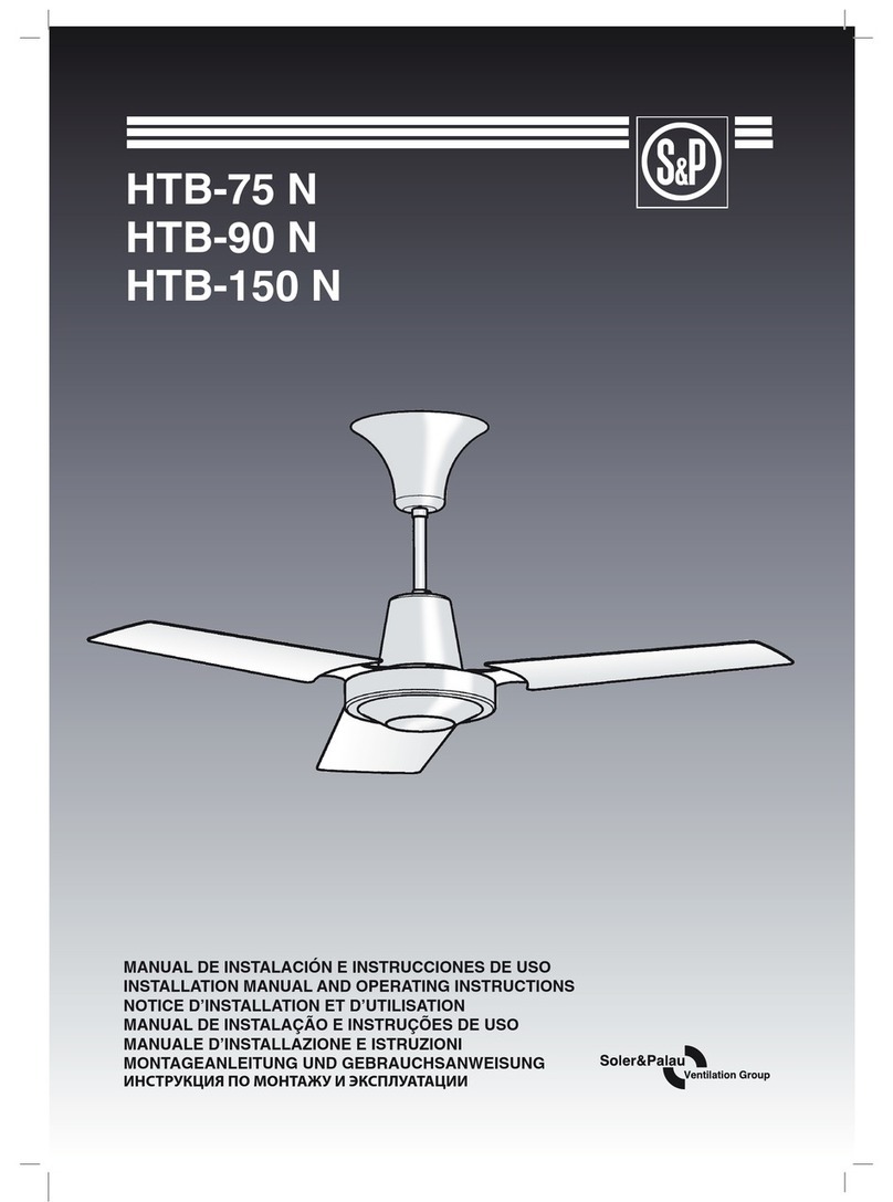
Soler & Palau HTB-75 N Technical Document

Soler & Palau

Soler & Palau HTB-75 N Technical Document

Soler & Palau TRe Series Instruction manual

Soler & Palau

Soler & Palau TRe Series Instruction manual

Soler & Palau WA12 Assembly instructions

Soler & Palau

Soler & Palau WA12 Assembly instructions

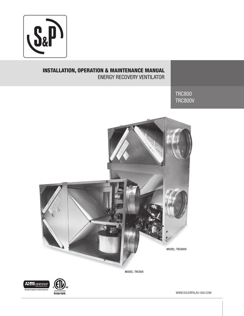
Soler & Palau TRC800 Instruction manual

Soler & Palau

Soler & Palau TRC800 Instruction manual

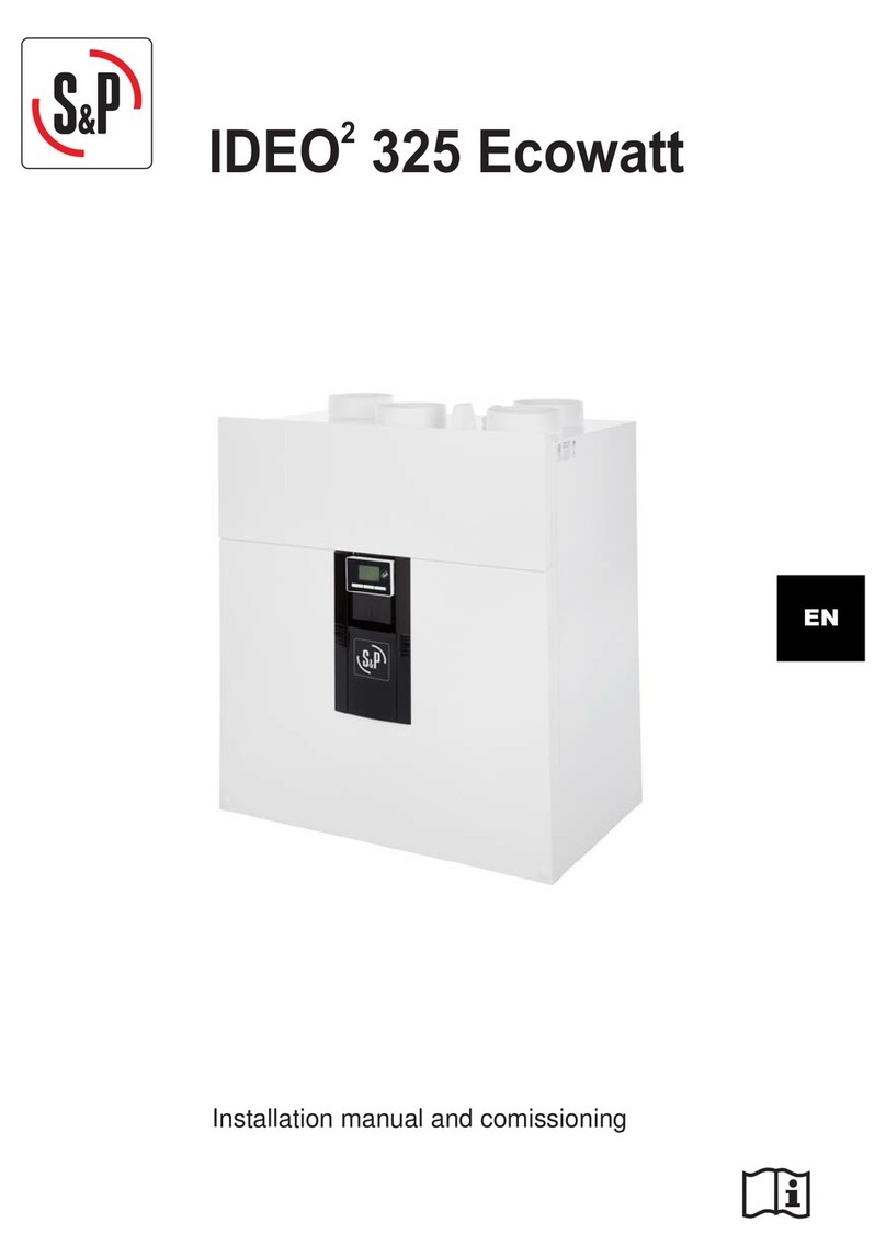
Soler & Palau IDEO2 325 Ecowatt Operating instructions

Soler & Palau

Soler & Palau IDEO2 325 Ecowatt Operating instructions

Soler & Palau WA COMPACT Series User manual

Soler & Palau

Soler & Palau WA COMPACT Series User manual

Soler & Palau HTD-130 MR Technical Document

Soler & Palau

Soler & Palau HTD-130 MR Technical Document

Soler & Palau CAD HE 450 EC H TSP User manual

Soler & Palau

Soler & Palau CAD HE 450 EC H TSP User manual

Soler & Palau RenewAire HE Series User manual

Soler & Palau

Soler & Palau RenewAire HE Series User manual

Soler & Palau powervent PV-150X Assembly instructions

Soler & Palau

Soler & Palau powervent PV-150X Assembly instructions

Soler & Palau powervent PV-100X Assembly instructions

Soler & Palau

Soler & Palau powervent PV-100X Assembly instructions

Soler & Palau Breidert JencoFan Losone Select Series User manual

Soler & Palau

Soler & Palau Breidert JencoFan Losone Select Series User manual

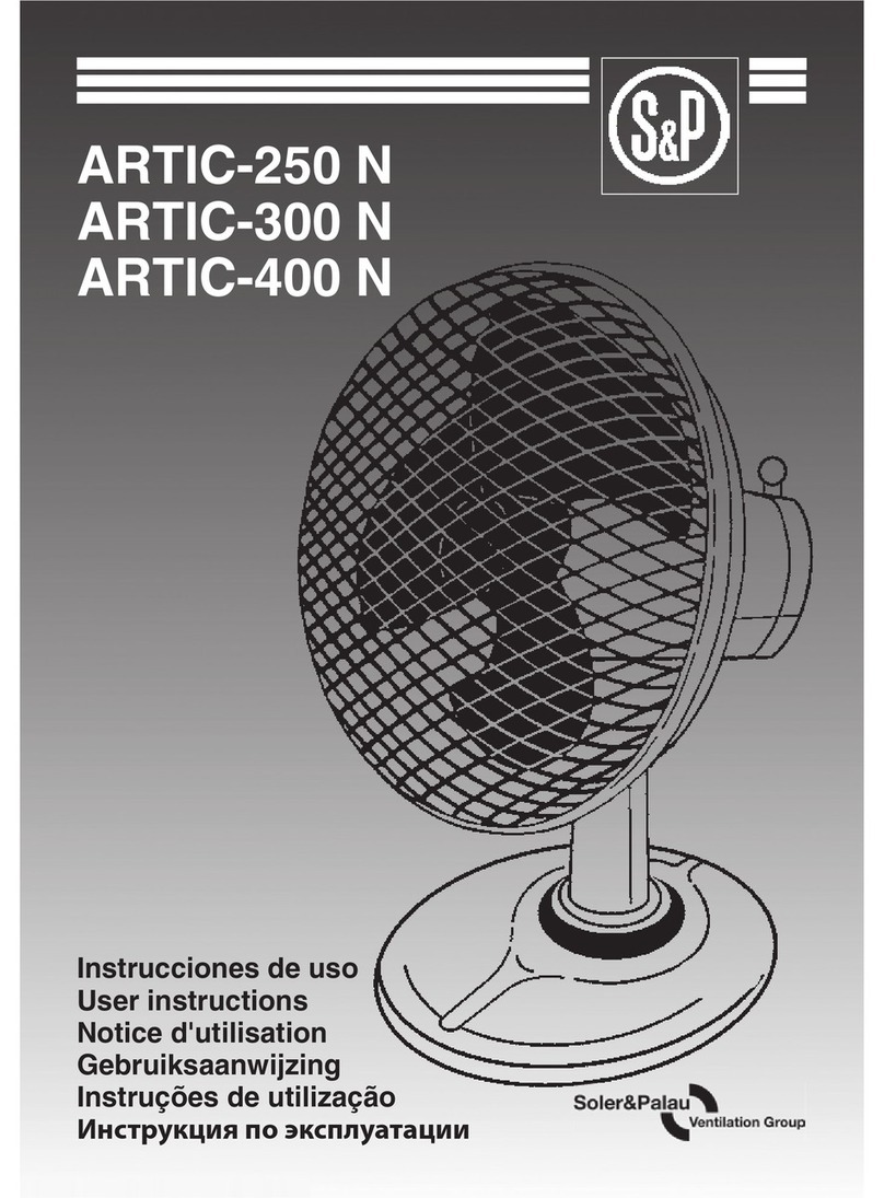
Soler & Palau ARTIC-400 R User manual

Soler & Palau

Soler & Palau ARTIC-400 R User manual

Soler & Palau SQB User manual

Soler & Palau

Soler & Palau SQB User manual

Soler & Palau OSAK-125 Assembly instructions

Soler & Palau

Soler & Palau OSAK-125 Assembly instructions

Soler & Palau FF100 User manual

Soler & Palau

Soler & Palau FF100 User manual

Soler & Palau SIDEWALL SWF-100 Assembly instructions

Soler & Palau

Soler & Palau SIDEWALL SWF-100 Assembly instructions

Soler & Palau ARTIC-250 N User manual

Soler & Palau

Soler & Palau ARTIC-250 N User manual

Soler & Palau RenewAire GR Series User manual

Soler & Palau

Soler & Palau RenewAire GR Series User manual

Soler & Palau ARTIC-400 CN User manual

Soler & Palau

Soler & Palau ARTIC-400 CN User manual

Soler & Palau CHEMINAIR 400 User manual

Soler & Palau

Soler & Palau CHEMINAIR 400 User manual

Soler & Palau TRCeN500/V Instruction manual

Soler & Palau

Soler & Palau TRCeN500/V Instruction manual

Soler & Palau ELEKTRODESIGN DUOVENT COMPACT RV TOP 800 User manual

Soler & Palau

Soler & Palau ELEKTRODESIGN DUOVENT COMPACT RV TOP 800 User manual

Soler & Palau TD-SILENT SERIES User manual

Soler & Palau

Soler & Palau TD-SILENT SERIES User manual

Popular Fan manuals by other brands

Wirata F-709A instruction manual

Wirata

Wirata F-709A instruction manual

Broan 504 instructions

Broan

Broan 504 instructions

Craftmade BW116-HW installation guide

Craftmade

Craftmade BW116-HW installation guide

Zehnder Rittling ComfoAir 155 WMe User/Homeowner Guide

Zehnder Rittling

Zehnder Rittling ComfoAir 155 WMe User/Homeowner Guide

Airworks 16MPWA owner's manual

Airworks

Airworks 16MPWA owner's manual

Daikin Sky Air Advance Series Installer's reference guide

Daikin

Daikin Sky Air Advance Series Installer's reference guide

ORIGO TF-29RC instruction manual

ORIGO

ORIGO TF-29RC instruction manual

Vents Solo RA1-35A-9 P user manual

Vents

Vents Solo RA1-35A-9 P user manual

Mitsubishi Electric V-251BZ-HK instruction manual

Mitsubishi Electric

Mitsubishi Electric V-251BZ-HK instruction manual

Fantech VHR 2004 installation manual

Fantech

Fantech VHR 2004 installation manual

Oceanic OCEAVB40B user manual

Oceanic

Oceanic OCEAVB40B user manual

Honeywell 527HHON001BLK owner's manual

Honeywell

Honeywell 527HHON001BLK owner's manual

Excellent Electrics DX5-000090 Instructions for use

Excellent Electrics

Excellent Electrics DX5-000090 Instructions for use

TOTALINE TOTALINE P707 Installation and operation instructions

TOTALINE

TOTALINE TOTALINE P707 Installation and operation instructions

Elba ETWF-A4140RC owner's manual

Elba

Elba ETWF-A4140RC owner's manual

Hunter Pro's Best installation manual

Hunter

Hunter Pro's Best installation manual

Envirovent energisava250 installation guide

Envirovent

Envirovent energisava250 installation guide

Trox Technik AXO/BVAXO Installation and operating manual

Trox Technik

Trox Technik AXO/BVAXO Installation and operating manual

manuals.online logo
manuals.online logoBrands
  • About & Mission
  • Contact us
  • Privacy Policy
  • Terms and Conditions

Copyright 2025 Manuals.Online. All Rights Reserved.