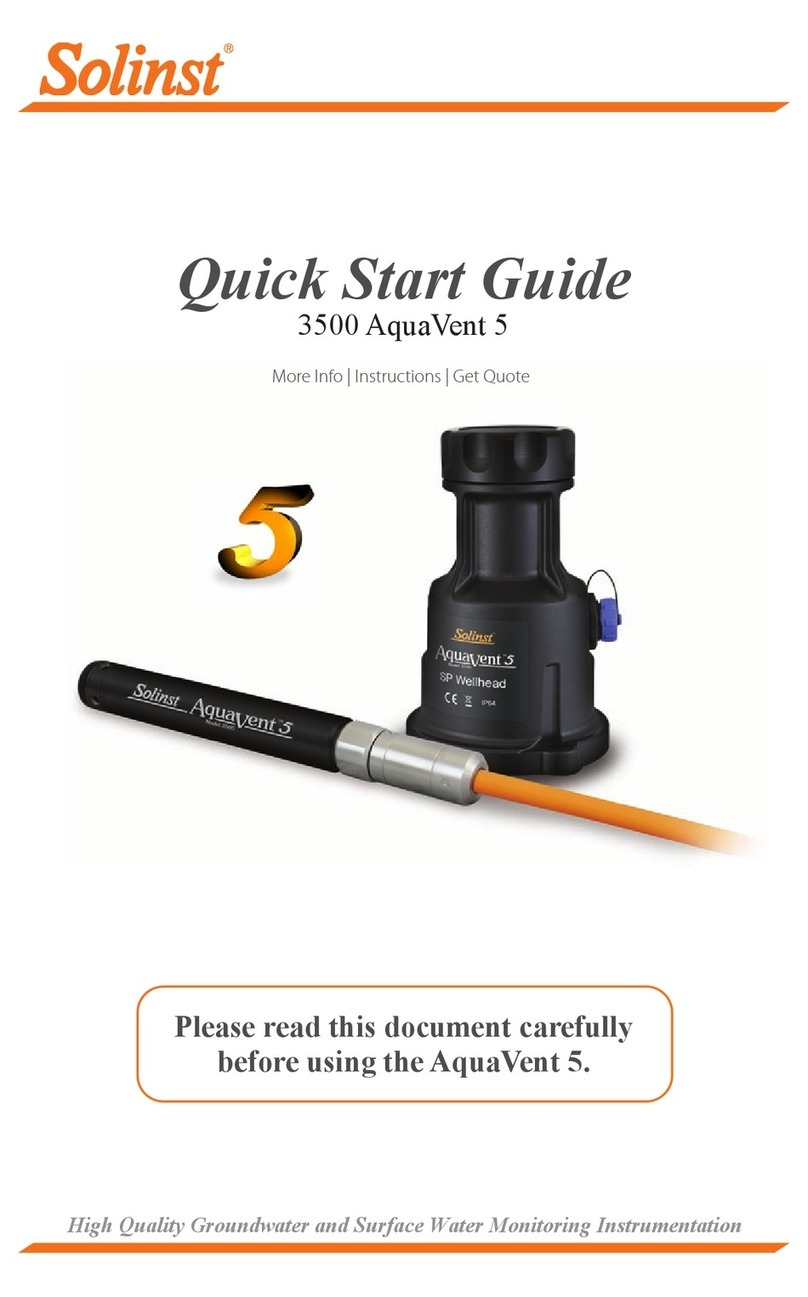
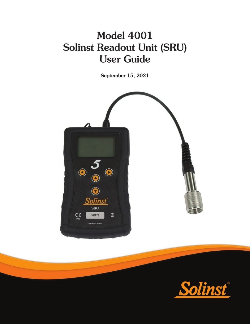
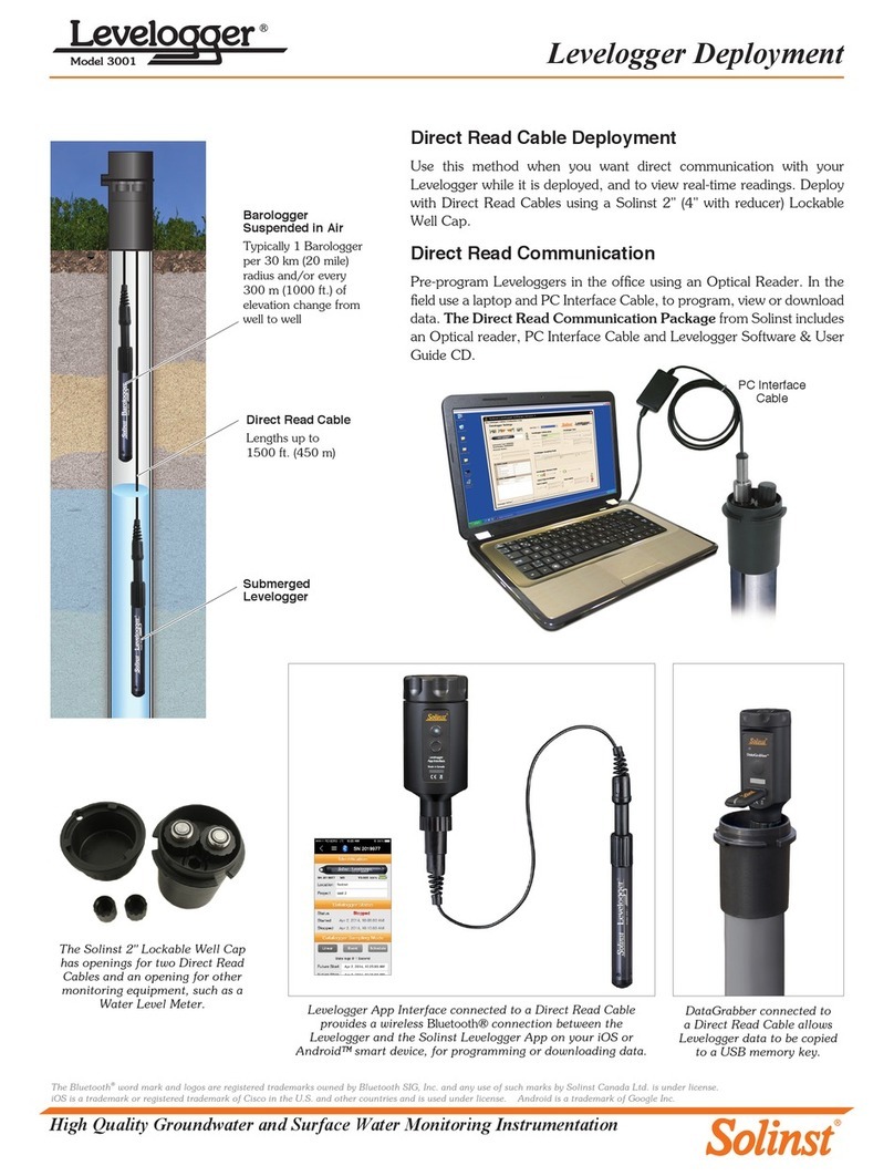
Solinst AquaVent M5 User manual

High Quality Groundwater and Surface Water Monitoring Instrumentation
Quick Start Guide
3500 AquaVent
Please read this document carefully
before using the AquaVent.

Getting Started
1. Download the software from: www.solinst.com/downloads
and install Levelogger Software on your PC.
2. Install the Wellhead batteries. The Wellhead uses 4 user-
replaceable 1.5V AA lithium batteries.
3. Connect the Wellhead and logger to the Vented Cable:
Support
Hanger
Bracket
- 2 -
Note: See page 6 for instructions to install the Support Hanger
Bracket, as shown at right.
Note: For information on using your AquaVent logger with
MODBUS or SDI-12 protocols, see separate User Guides. Battery
Compartment
SP
Wellhead
Vented
Cable
AquaVent
Logger
10-Pin (SP)
Connection
Alignment socket in the
Vented Cable connectors
Alignment pin in the Wellhead
and logger connectors
Coupling
Connector
Body
Line up the alignment socket in the Vented Cable connector with the
alignment pin in the Wellhead connector.
Carefully push the connectors together. Twist the cable connector
slightly until you will feel a small click when the properly aligned
connection is made.
Tighten the stainless steel coupling while holding the stainless steel cable
connector body still. Tighten the coupling until it seats. Do not twist the
Vented Cable or Wellhead.
Follow the same procedure when connecting the logger to the Vented
Cable.
Well Cap
Base

AquaVent Quick Start Guide
4. Connect the USB Connector
Cable to the 10-Pin (Solinst
Protocol) connection on the
Wellhead, then plug the USB
Connector Cable into your
computer.
Programming AquaVent Loggers
Note: Ensure you are using the latest software, and firmware versions for your AquaVent logger and
Wellhead. Visit www.solinst.com/downloads, or use the software update feature for help.
1. Start the Levelogger Software, and select the appropriate Com Port for the connected device.
2. In the Datalogger Settings tab, click the ‘Retrieve Settings” icon. This will display the
current programmed settings for the connected AquaVent.
3. You can now customize the AquaVent Project ID, Locations, sampling regime, and start and
stop times.
AquaVent Datalogger Settings Window
Note: Clicking on the embedded in the software will provide you with a short explanation of that feature,
e.g. Com Port, Slate Mode, Time Synchronization, etc.
Starting and Stopping AquaVent Loggers
1. If desired, enter a Future Start and/or Future Stop time.
2. When the ‘Start’ icon is selected, all settings are applied to the AquaVent logger and it will start
logging at the specified time.
3. To start logging immediately, do not fill in the Future Start field, and click the ‘Start Now’ icon.
Tip
If a number of
AquaVent loggers
are to be programmed
with identical inputs, clicking
the “Save Default Settings”
icon will create a template.
Note: When start is selected, a window will pop-up as an alert that the previous data will be erased.
4. To stop the AquaVent immediately, click the “Stop Now’ icon.
Tip
The ‘Future Start’ and
‘Future Stop’ options are
ideal for synchronizing the
data collection of multiple
loggers.
USB Connector Cable
- 3 -

Downloading and Working with Data
1. Click the ‘Data Control’ tab to access the “Data Control’ window.
This window is laid out in three sections: datalogger settings, tabular
data, and graphical data.
2. To download data from a connected logger, select the
‘Download Data from Datalogger’ icon. There are four
options for downloading data: All Data, Append Data,
Partial Download, and Recover Previous Log. The data will
be presented in tabular and graphical formats.
Note: The default directory for downloaded and saved data is:
<C:\Program Files\Solinst\Levelogger4_4\Data>
Data is saved as an *.xle file.
3. To save data, click the “Save Data” icon and input the desired name for the saved file.
4. To export the data file for use in other software programs, click the ‘Export’ icon. The
file can be exported as a *.csv or *.xml file.
Data Control Window
Real Time View
Real Time View provides on-screen measurement as data is being recorded by the connected logger.
A view rate is set independently of the logging period of the AquaVent and does not interfere with
internal logging taking place. To take a reading at any specific time, click and that reading will
be added to the displayed data. The data can be exported and saved.
Note
To change the
default directory for
downloaded data, use
the ‘Configuration’
menu at the top of the
software window. Select
‘Application Settings’
and input or navigate
to a different folder
destination. Click ‘OK’.
Tip
The *.csv and *.xml file
formats are supported
and can be imported by
most spreadsheet and
database programs.
The data graph can be
exported to a *.bmp
file or a *.png file by
clicking File > Export >
Graph.
Compensate the Data
Click the ‘Data Wizard’ tab to open the ‘Data Wizard’ window. In this
window the ‘Wizard’ will guide you through Manual Data Adjustments
(elevation or height of water conversions) and Parameter Adjustments
(units, elevation, density adjustments) on your open data files. Multiple
AquaVent data files can be compensated at once.
Tip
‘Manual Data
Adjustments’ allow you
to use manual water
level measurements
to adjust your data to
depth to water readings.
- 4 -

AquaVent Quick Start Guide
AquaVent Ranges
AquaVent Models are rated to a specific submergence depth (Table 1).
The choice of model depends on the accuracy of the level required
and the submergence depth. Most important, your selection should be
based on the maximum anticipated water level fluctuation.
Note
The AquaVent logger
can withstand over-
pressurization of 2
times the intended
range, e.g. a Model M10
can accommodate a
fluctuation of
20 meters or 60 feet and
still record pressure.
However, over-range
accuracy is not
guaranteed.
AquaVent
Models
Submergence
Depth Accuracy
M5 5 m (16.4 ft.) ± 0.3 cm (0.010 ft.)
M10 10 m (32.8 ft.) ± 0.5 cm (0.016 ft.)
M20 20 m (65.6 ft.) ± 1 cm (0.032 ft.)
Table 1 - AquaVent Ranges
Measurement Fundamentals
Note
To adjust all readings
in your AquaVent data
file to depth to water
below a well casing (d),
record a manual water
level measurement using
a water level meter.
This reading should
correspond in data and
time with an actual
AquaVent recording.
Use this as a reference
datum in the Manual
Data Adjustment option
in the Software Data
Wizard.
AquaVent loggers detect both
water (W) and barometric
pressure (+B). However, a vent
tube to surface allows barometric
effects on the pressure sensor
to be eliminated (-B). Therefore,
AquaVent loggers provide
readings of the actual pressure
of just water above the pressure
sensor zero point (A).
A = (W + +B) +(-B)
Therefore, A=W
A= AquaVent readings
W= Water column height
+B = Barometric pressure
detected by the pressor sensor
-B = Barometric pressure
applied through the vented cable
Verifying Readings
Compare AquaVent readings (A)
with a measured depth to water
level value (d) (Using a Water
Level Meter). The deployment
depth of the AquaVent (D),
minus the manual depth to water
measurement (d), should equal
the AquaVent reading:
D - d = A
- 5 -
Tip
It is recommended to
take a manual water
level measurement
before installing an
AquaVent logger, shortly
after installation,
periodically during your
monitoring interval,
and at the end of your
measurement period.
Use these measurements
to verify AquaVent
readings, and for data
adjustments later on.
Ensure you take manual
readings as close in
time as possible to a
scheduled AquaVent
reading.

- 6 -
Before Deployment
Before deployment, make sure you do the following:
• Program your AquaVent logger, using Levelogger Software, with the
correct project identification, memory mode, sampling regime, time, etc.
• Set a future start time in the office, or start the AquaVent logger in
the field using Levelogger PC Software and a laptop, or the Solinst
Levelogger App & Interface.
• Determine borehole depth to ensure AquaVent logger does not touch
the bottom of the well (avoid submergence in sediment)
• Record the deployment depth of your AquaVent logger.
After Deployment
After deployment, make sure you do the following:
• Take a manual depth to water measurement after the well has stabilized
(approximately 10 minutes))
• Take another manual depth to water measurement just before removing
the AquaVent logger from the well
AquaVent Field Notes
Note: It is useful to synchronize the times of all AquaVent loggers being
used for the same project.
Note: For tips, precautions, and more information on installations in
different environments and applications, see the latest AquaVent
User Guide.
Deployment
• The AquaVent system is designed to be conveniently installed on a
2" well casing (4" using an adaptor). However, other installations are
acceptable, if proper precautions and recommendations are followed.
• Leave at least 2" (50 mm) of slack in the Vented Cable at surface to
allow you to lift the AquaVent Wellhead from the well cap base to
provide access for manual depth to water measurements, without
disturbing the AquaVent logger from its down hole position.
• The Wellheads have a rating of IP 64 (dust and splash resistant), so
should not be submerged at anytime. They can be secured inside an
enclosure, however, it must be vented to equalize atmospheric pressure.
• Do not drop the AquaVent logger into the water, carefully lower it into
place. Avoid installing in areas where “water hammer” or hydraulic
jump” (very sudden, large increases in pressure) may occur.
• Be careful not to nick or bend the Vented Cable during installation (use a
maximum 1" (25 mm) bend radius as a precaution).
Note: The length of the Vented Cable should not be assumed as the
deployment depth, as there may be some slack in the cable,
especially when using the hanger bracket
• Use a Solinst Model 101 or 102 Water Level Meter to take a manual
depth to water measurement that will be used to verify AquaVent
readings
• Determine the minimum and maximum expected water levels, as
AquaVent loggers must remain submerged for the entire monitoring
period.
Support Hanger
Bracket Installation
AquaVent Quick Start Guide
In-Field Communication
There are two SP Wellhead Cable options for communicating with AquaVent loggers in the field.
• The USB Connector Cable allows you to connect to a field laptop for communication using Levelogger
Software (see image on Page 1).
• The App/DataGrabber Connector Cable allows you to connect to a Levelogger App Interface for
communication using the Solinst Levelogger App, or to a DataGrabber for downloading data to a
USB device.
- 7 -
Note
The SPX Wellhead has
additional LED definitions
related to MODBUS and
SDI-12 operation.
For information on
communication using
MODBUS or SDI-12 Protocols,
see separate User Guides.
App/DataGrabber
Connector Cable DataGrabber
LED: Wellhead Connection Status
The AquaVent Wellheads have a multicolour LED light which
indicates the status and operation of the AquaVent:
• Fast multicolour cycle 3 times: Wellhead is powering-on
• Fast 10 cycles alternating blue/green: Wellhead has successfully
connected to the PC using the USB Connector Cable
• Fast 10 cycles alternating blue/red: USB connection has been
dropped
• Flashing yellow: The Wellhead is communicating with the PC Software
Maintenance
As with any monitoring project, you should select the proper equipment and determine a maintenance
schedule based on the environment specific to your application.
To ensure the vent tube remains dry, the AquaVent loggers and Wellheads contain permanent
desiccants and hydrophobic membranes at the connections to the Vented Cable—there is no need
to replace them. Please see our technical bulletin on Vented Cable Design, Use, and Maintenance
for more details.
Other maintenance tips include (see the AquaVent User Guide for more details):
• Replace the o-rings at the Vented Cable connections on the AquaVent logger and the Wellhead.
• Keep the dust caps on all of the connections, when not in use.
• Store the AquaVent logger in its case, and the Vented Cable on its spool when not in use.
• Ensure connections are clean before assembling. Clean the AquaVent logger as required.
• Replace the Wellhead batteries as required (four user-replaceable 1.5V AA lithium batteries).
AquaVent Sampling Rate Battery Life Estimate
8 readings per second 10 days
1 reading per second 3 months
1 reading per minute 8 years
Levelogger App Interface

(#112802) June 19, 2018
Printed in Canada
For further information contact: Solinst Canada Ltd.
Fax: +1 (905) 873-1992; (800) 516-9081 Tel: +1 (905) 873-2255; (800) 661-2023
35 Todd Road, Georgetown, Ontario Canada L7G 4R8
®Solinst and Levelogger are registered trademarks of Solinst Canada Ltd.
Troubleshooting
Levelogger PC Software:
1. You must have administrator privileges to install software on a computer.
2. Windows 7, 8, and 10 Operating Systems support Levelogger Software.
AquaVent data has been accidentally erased:
If the AquaVent has been restarted and the old data has not been saved, select the download option
“Recover Previous Log”. This will download your previous data set.
Try the following if your AquaVent is not communicating with Levelogger PC
Software, or you are getting a communication error message:
1. Make sure you have installed the batteries correctly:
• Ensure proper polarity, paying attention to the positive {+} and negative {-} symbols etched in
the holder
• Ensure proper alignment; the spring contacts in the housing should be lined up with the
protruding contacts on the bottom of the battery holder
2. Check the Vented Cable connections to the AquaVent logger and Wellhead. Ensure they are
lined-up correctly and there is no dirt or debris in the connection.
3. Make sure you are using the correct Wellhead Connector Cable to connect to the PC.
• You must be using a USB Connector Cable connected to the 10-pin Solinst Protocol connection
on the Wellhead. The cable and connection are colour-coded orange.
4. Check that the USB Connector Cable is connected to the same Com Port that is
chosen in the upper middle of the Main Window of the Levelogger Software.
5. Check the Com port settings. They should be as follows:
• Bits per second: 9600
• Data bits: 8
• Parity: None
• Stop bits: 1
• Flow control: None (This may have been set to Xon/Xoff – change it to None, Select [OK]
and back out of this pathway.)
6
. Try communicating with another AquaVent logger, Wellhead, Vented Cable or USB Connector
Cable.
7. Try using a different computer.
8. If problem persists, contact Solinst.
To reset the AquaVent battery indicator, after replacing the Wellhead batteries:
Go to the Diagnostic Utility in Levelogger Software, click “Run Diagnostics”, then click “Reset
AquaVent Battery Indicator”.
Note: For diagnostic purposes, you may want to install the end of the Vented Cable with the serial number
to the surface connection at the Wellhead.
This manual suits for next models
3
Table of contents
Other Solinst Data Logger manuals

Solinst
Solinst Levelogger 5 Series User manual

Solinst
Solinst Remote Radio Link User manual

Solinst
Solinst LevelVent 5 User manual

Solinst
Solinst Levelogger 3001 User manual

Solinst
Solinst AquaVent 5 3500 User manual

Solinst
Solinst Levelogger Series User manual

Solinst
Solinst Barologger 3001 Gold User manual

Solinst
Solinst Levelogger Series User manual

Solinst
Solinst Levelogger Gold User manual

Solinst
Solinst LevelVent User manual