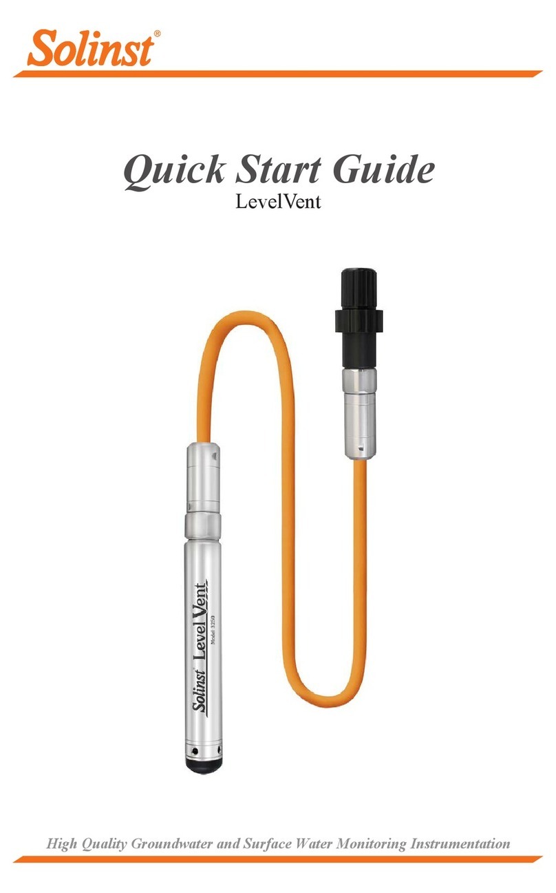
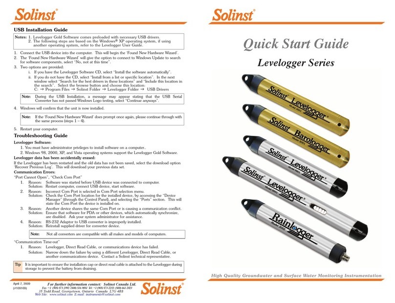
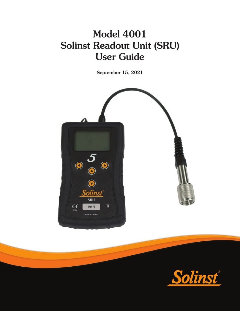
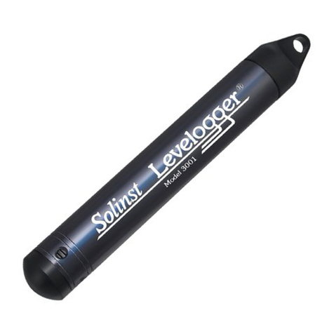
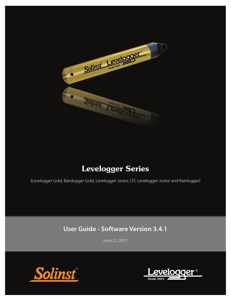
Solinst Levelogger 5 Series User manual

- 2 -
PC Interface Cable
Optical Readers
1. Connect the Levelogger to the communications device and start the software.
2. Select the appropriate Com Port for the connected communications device from the
centre drop-down menu.
3. Click the ‘Retrieve Settings from Levelogger’ icon. This will retrieve and display
information about the connected datalogger, and any current programmed
settings.
4. You can now customize the Levelogger including your Project ID, Location, Sampling
Mode and Rate, and Future Stop and Start times.
Programming the Levelogger
Installing the Software
To begin using your Levelogger, download the newest version of Levelogger Software
and User Guide by visiting: www.solinst.com/downloads/
Installing the Hardware
Connect your datalogger to a computer using either the Optical Reader (Desktop Reader 5 or
Field Reader 5) or PC Interface Cable.
Note: Ensure the Levelogger is operating with the latest firmware, and that you are using
the latest software. Visit the Solinst website (www.solinst.com/downloads/) or use
the update notifications in the software for assistance. If older Levelogger versions
are used, refer to our Compatibility Chart on the Downloads page.
Tip: If a number of Leveloggers are to be programmed with identical inputs,
clicking the ‘Save Default Settings’ icon will create a template.
Note: If you are using an old style Optical Reader or Direct Read Cable with a
Levelogger 5 Series datalogger, you will need to use an L5–Edge DRC Adaptor.
L5 Direct
Read Cable
Desktop Reader 5
Field Reader 5

Levelogger 5 Series Quick Start Guide
- 3 -
Datalogger Settings Window
Rainlogger 5 Programming
The Rainfall Calibration Constant ‘value’ of the tipping
bucket rain gauge used with the Rainlogger is required
when programming the Rainlogger 5. Consult the
Levelogger User Guide for more information on
programming the Rainlogger 5.
Levelogger 5 LTC Calibration
Before deploying your Levelogger 5 LTC, be sure to
calibrate the instrument. To begin calibration, open the
‘Conductivity Cal’ tab and follow the steps provided.
Consult the Levelogger User Guide for more information,
or view the LTC Calibration Video on our YouTube Channel:
https://www.youtube.com/user/SolinstCanadaLtd
Note: Clicking on the in the software will provide you with a
short explanation of that feature, e.g. Com Port, Slate Mode,
Time Synchronization, etc.

- 4 -
2. When “Yes” is selected, all settings are applied to the Levelogger and it will start logging
at the specified time.
3. To stop the Levelogger immediately, click the ‘Stop Now’ icon.
Downloading and Working with Data
1. Click the ‘Data Control’ tab to access the ‘Data Control’ window. This window is
laid out in three sections: Levelogger settings, tabular data, and graphical data.
2. To download the data from a connected Levelogger, select the ‘Download Data
from Levelogger’ icon. There are four options for downloading data. They are:
All Data, Append Download, Partial Download and Download Files.
The data will be presented in both tabular and graphical format.
3. To save data, click the ‘Save Data’ icon and input desired name for the saved file.
4. To export the file for use in other software, click the ‘Export’ icon. The file can be
exported to a *.csv or *.xml file.
Note: To change the default directory for downloaded data, use the ‘Configuration’
menu at the top of the software window. Select ‘Application Settings’ and input
or navigate to a different folder destination. Click ‘OK’.
Starting and Stopping the Levelogger
1. If desired, enter a Future Start and/or Future Stop Time. To start logging
immediately, do not fill in a future start time and click the ‘Start Now’ icon.
Note: When the ‘Start’ icon is selected, a window will pop-up to indicate how much
memory is available. Selecting “Yes” ignores the message and starts the
datalogger immediately. Selecting “No” gives you the chance to access the ‘Data
Control’ tab to download and/or delete data files using the ‘Download Files’
option, to free-up memory.
Note: The default directory for downloaded and saved data is in the ‘Data’ folder:
<C:\Program\Files\Solinst\Levelogger 4_5\Data>. Data is saved as a .xle
data file.
Tip: The ‘future start’ and ‘future stop’ options are ideal for synchronizing the data
collection of multiple Leveloggers and Barologgers.
Tip: The *.csv and *.xml file formats are supported and can be imported by most
spreadsheet and database programs.
The data graph can be exported to a *.bmp file or a *.png file by clicking
File > Export >Graph.
Levelogger 5 Series Quick Start Guide
- 5 -
Data Control Window
DataGrabber 5
Connect a DataGrabber 5 to an in-field
Levelogger via an L5 Direct Read Cable
or L5 Threaded or Slip Fit Adaptor, and
transfer data to a USB key.
Real Time View
Real Time View provides on-screen measurement as data is being recorded by the
connected datalogger. A view rate is set independently of the logging period of the
Levelogger and does not interfere with internal logging taking place. To take a reading at
any specific time, click and that reading will be added to the displayed data. The data
can be exported and saved.
Compensate the Data
Click the ‘Data Wizard’ tab to open the ‘Data Wizard’ window. In this window the ‘Wizard’
will guide you through Barometric Compensation, Manual Data Adjustments, and Parameter
Adjustments on your open data files. There are two convenient options; Basic or Advanced
compensation. This allows you to choose just one, two, or all three types of compensation.
Multiple Levelogger files can be barometrically compensated at once, using one open
Barologger file.
Tip: ‘Manual Data Adjustment’ allows you to use manual water level measurements to
adjust your data to depth to water readings.

- 6 -
Levelogger Field Measurement
Levelogger 5 Ranges
Each model of Levelogger is rated for a specific submergence depth (Table 1). The choice of
model largely depends on the accuracy of the water level required and the submergence depth.
The selection, however, should be based on the maximum anticipated water level fluctuation.
Model Submergence Depth Accuracy
Barologger Air only ± 0.05 kPa
M5 5 m (16.4 ft.) ± 0.3 cm (0.010 ft.)
M10 10 m (32.8 ft.) ± 0.5 cm (0.016 ft.)
M20 20 m (65.6 ft.) ± 1 cm (0.032 ft.)
M30 30 m (98.4 ft.) ± 1.5 cm (0.064 ft.)
M100 100 m (328.1 ft.) ± 5 cm (0.164 ft.)
M200 200 m (656.2 ft.) ± 10 cm (0.328 ft.)
Table 1 – Levelogger 5 Ranges
Measurement Fundamentals
Leveloggers (L) measure the total pressure acting on a
transducer at their zero point/sensor. The total pressure is
caused by the column of water lying above the Levelogger
pressure sensor AND the barometric (atmospheric) pressure
acting on the water surface. To compensate for barometric
pressure fluctuations and get true height of water column
measurements (H), a Barologger (B) is required, i.e.:
Levelogger Reading (L) – Barologger Reading (B)
=
Height of Water Column (H)
Verifying Readings
The best recommendation is to compare barometrically
compensated Levelogger data (H) with a manually measured
depth to water level value (d) (using a Water Level Meter).
Tip: To adjust all readings in your Levelogger file to
depth to water below a well casing (d), record a manual
water level measurement using a water level meter. This
reading should correspond in date and time with an actual
Levelogger recording. Use this as a reference datum in
the Manual Data Adjustment option in the Levelogger
Software Data Wizard.

Levelogger 5 Series Quick Start Guide
- 7 -
Levelogger Field Notes
Before Deployment
Before deployment, make sure you do the following:
• Program your Levelogger, using Levelogger Software, with the correct project
identification, memory mode, sampling regime, time, etc.
• Set a future start time, or start the Levelogger if deploying on a wireline/Kevlar cord
(Leveloggers can be started after deployment if using an L5 Direct Read Cable)
• Determine borehole depth to ensure the Levelogger does not touch the bottom of the well
(avoid submergence in sediment)
• Determine the minimum and maximum expected water levels, as Leveloggers must remain
submerged for the entire monitoring period, and Barologgers must not be submerged
• Use a Solinst Model 101 or 102 Water Level Meter to take a manual depth to water
measurement that will be used to verify Levelogger readings
Note: It is useful to synchronize the times of all Leveloggers and Barologgers being used
for the same project.
Note: The Levelogger 5 can withstand over-pressurization of 2 times the intended range,
e.g. a Model M10 can accommodate a fluctuation of 20 meters or 60 feet and still
record pressure. However, over-range accuracy is not guaranteed.
A single Barologger 5 can be used to
compensate all Leveloggers on site,
within a 30 km/20 mile radius and
with every 300 m (1000 ft.) change in
elevation. Ensure that your Barologger
will start logging within at least 3 hours
of your Levelogger start time.
Tip: It is recommended to take a manual water level measurement before installing a
Levelogger, shortly after installation, periodically during your monitoring interval,
and at the end of your measurement period. Use these measurements to verify
Levelogger readings, and for data adjustments later on. Ensure you take manual
readings as close in time as possible to a scheduled Levelogger reading.

- 8 -
After Deployment
After deployment, make sure you do the following:
• Take a manual depth to water measurement after the well has stabilized (approximately
10 minutes)
• Take another manual depth to water measurement just before removing the Levelogger
from the well
Deployment
• Deploy your Levelogger and Barologger using an L5 Direct Read Cable for down-well
communication, or use an inexpensive wireline or Kevlar cord.
• Install the Barologger in a similar thermal environment as the Levelogger
• The Barologger should be suspended beyond the frost line and deep enough to avoid large
temperature fluctuations
• Ensure the Barologger location is vented to atmosphere
Wireline/Cord Deployment Direct Read Deployment
Well Caps
The Model 3001 2" (or 4" with Adaptor) Well Cap
Assembly provides a secure method of installing your
Levelogger using wireline/Kevlar cord or L5 Direct
Read Cables. A Support Hanger Bracket is available for
supporting and organizing down well wires or cords, or
for coiling extra L5 Direct Read Cable lengths.
Note: For information on other types of installations, see the latest
Levelogger User Guide.

Levelogger 5 Series Quick Start Guide
- 9 -
In-field Communication
If you have installed your Levelogger using wireline/Kevlar cord, you can communicate with
your Levelogger via a Field Reader 5 or Desktop Reader 5 and Levelogger Software on a
laptop PC (you can also use an older style Optical Reader with an L5–Edge DRC Adaptor).
If you have installed your Levelogger using an L5 Direct Read Cable, you can communicate
with your Levelogger via a PC Interface Cable and Levelogger Software on a laptop PC,
using a Levelogger 5 App Interface and the Solinst Levelogger App on your mobile device,
or connect a DataGrabber 5, without removing the Levelogger from the well.
Field Reader 5
PC Interface Cable
Levelogger 5 App Interface
Note: An L5 Threaded or Slip Fit Adaptor can be used to directly connect a
Levelogger to a Levelogger 5 App Interface or DataGrabber 5.
Desktop Reader 5
DataGrabber 5

- 10 -
Note: All Leveloggers should be deployed and stored with the installation cap or L5 Direct
Read Cable attached. This prevents unnecessary battery drainage and protects the
optical eye.
Maintenance
As with any monitoring project, you should select the proper equipment and determine a
maintenance schedule based on the environment specific to your application.
Maintenance tips include:
• Inspect regularly, and replace the o-ring at the optical end of the Levelogger if damaged
• Clean the optical eye of the Levelogger with a clean, soft cloth or cotton swab
• Rinse the Levelogger body using a mild, non-residual, non-abrasive household cleaner
• Use a very soft-plastic bristled brush, if needed, to clean the Levelogger body
• Do not insert any object through the circulation holes at the sensor end of the Levelogger
• See the Levelogger User Guide Maintenance Section if simple household cleaners are not
sufficient for certain issues, such as hard water build up
• Clean Levelogger 5 LTC conductivity sensor pins before calibration and before/after
deployment—see the Solinst Levelogger User Guide
• Stop the Levelogger from recording before storing
• Store Leveloggers with the installation cap on and in the case they were originally provided in
• Store Leveloggers in above-freezing conditions
• Read our Technical Bulletin “Ensuring Proper Use and Maintenance of Leveloggers”
Note: A Solinst Biofoul Screen can be used to protect the Levelogger 5 from biofouling on
the pressure sensor, and the conductivity cell of a Levelogger 5 LTC.

Levelogger 5 Series Quick Start Guide
- 11 -
Levelogger Software:
1. You must have administrator privileges to install software on a computer.
2. The Windows 10 Operating System supports Levelogger Software.
Troubleshooting Guide
Communication Errors:
“Port Cannot Open”, “Check Com Port”
1. Reason: Software was started before USB device was connected to computer.
Solution: Restart computer, connect USB device, start software.
2. Reason: Incorrect Com Port is selected in Com Port selection menu.
Solution: Check the Com Port location for the installed device, by accessing the ‘Device
Manager’ (through the Control Panel), and selecting the “Ports” section. This
will state the Com Port the device is installed on.
3. Reason: Another device shares the same Com Port or is causing a communication
conflict.
Solution: Ensure that software for PDA or other devices, which automatically synchronize,
are disabled. Ask your system administrator for assistance.
“Communication Time-Out”, “Communication Error”
1. Reason: Levelogger, Direct Read Cable, or communications device has failed.
Solution: a) Narrow down the failure by using a different Levelogger, Direct Read Cable,
or another communications device.
b) Clean the optical eye/lens on the Levelogger and Optical Reader (Desktop
Reader 5 or Field Reader 5), or L5 Direct Read Cable, with a soft cloth.
c) Check that the communication cable is connected to the same Com Port that
is chosen in the upper middle of the Levelogger Software window.
d) Try using a different computer, to see if this is the cause of the problem.
e) If using a laptop (especially in conjunction with a Direct Read Cable) your
Com Port may not be powered adequately to receive/transmit data. Try using
a desktop computer to test this.
f) If problem persists, contact Solinst.

®Solinst is a registered trademark of Solinst Canada Ltd.
Solinst Canada Ltd. 35 Todd Road, Georgetown, Ontario Canada L7G 4R8
Tel: +1 (905) 873-2255; (800) 661-2023 Fax: +1 (905) 873-1992
(#114998) Printed in Canada September 1, 2020
Frequently Asked Questions
(Also see https://www.solinst.com/products/dataloggers-and-telemetry/3001-levelogger-series/
levelogger-faq/levelogger-faq.php)
How can I protect my Levelogger from corrosive or marine
environments?
The Levelogger 5 and Levelogger 5 LTC have a corrosion resistant coating. In harsher
chemical environments, you can protect the Levelogger using a thick membrane balloon
(e.g. helium) filled with non-corrosive/non-toxic fluid (tap water). As pressure changes,
the fluid encasing the dataloggers will transmit the pressure differential to the datalogger’s
pressure transducer, without exposing it to corrosive conditions. Continual monitoring is
recommended to assess the effectiveness of the protection at your site.
How do I install my Levelogger in a surface water application?
For installations within rivers, streams, wetlands, lakes and watershed or drainage basin
monitoring, the shallow pressure range (M5) Levelogger 5 or Levelogger 5 Junior should be
considered. For installation in streams or rivers, stilling wells can be constructed which shield
the instrument from the water turbulence. Alternatively, Leveloggers can be lowered into a
protective pipe or casing and then attached to a permanent fixture such as a bridge, pier or
hand driven marker/rod.
How do I protect my Levelogger from freezing?
To avoid icing/freezing and transducer damage, the easiest method is to lower the transducer
to a point in the water column below the frost line or ice formation depth. In water bodies
such as shallow streams, wetlands or ponds where icing/freezing may penetrate to the
bottom, install the Levelogger in a vented stilling well imbedded into the bottom of the water
body beyond the frost line.
If this is not possible, place the Levelogger inside a thick membrane balloon filled with a non-
toxic, non-corrosive anti-freeze solution or saltwater solution. Place the balloon in a section
of perforated, 30 mm (1.25") ID pipe and install the datalogger in the monitored water. The
antifreeze solution will protect the Levelogger from ice expansion at the pressure transducer,
yet transmit any pressure and temperature fluctuations that occur.
How do I protect my Levelogger from biofouling?
Use the Solinst Model 3001 Biofoul Screen.
Is Levelogger maintenance required?
Yes, consult the Solinst Technical Bulletin “Ensuring Proper Use and Maintenance of
Leveloggers” to maintain the long life of your instrument, based on the monitoring
environment specific to your application.
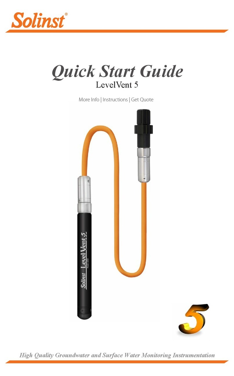
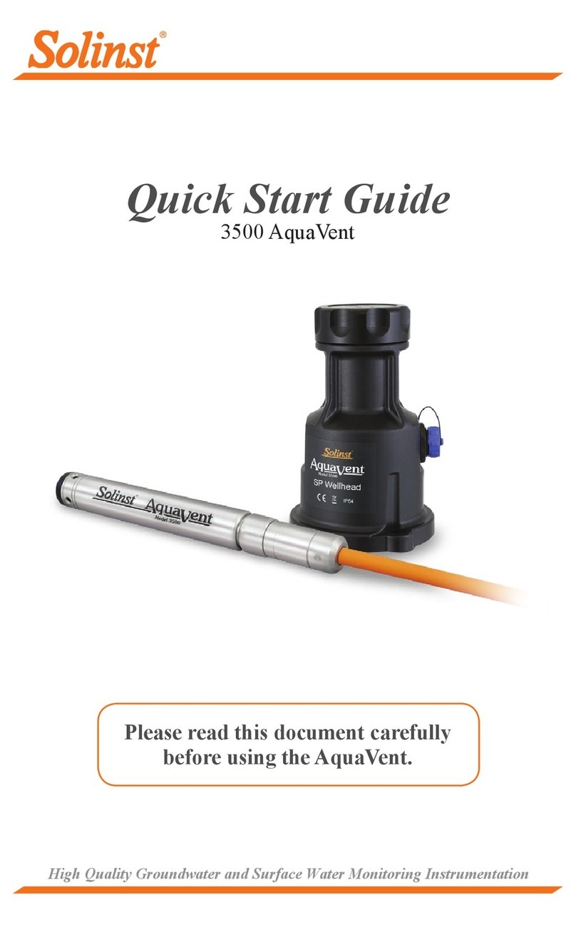
This manual suits for next models
8
Table of contents
Other Solinst Data Logger manuals

Solinst
Solinst SRU 4001 User manual

Solinst
Solinst Levelogger Series User manual

Solinst
Solinst Levelogger Gold User manual

Solinst
Solinst LevelVent 5 User manual

Solinst
Solinst Levelogger 3001 User manual

Solinst
Solinst Remote Radio Link User manual

Solinst
Solinst Barologger 3001 Gold User manual

Solinst
Solinst AquaVent 5 3500 User manual

Solinst
Solinst Levelogger Series User manual

Solinst
Solinst Levelogger 3001 Quick reference guide