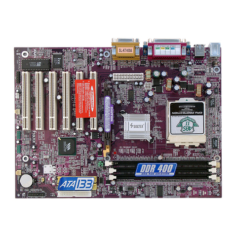
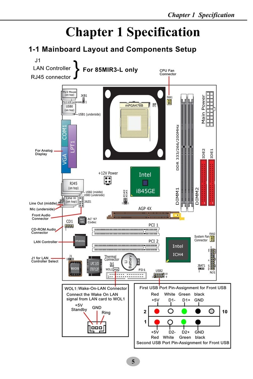
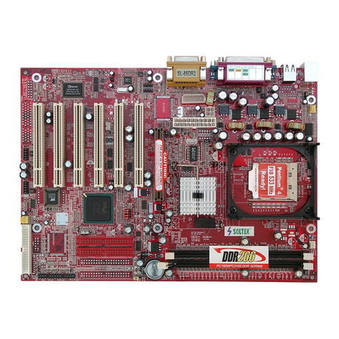
SOLTEK SL-85SID User manual

Mainboard
SL-85SID User Manual V1.0
R
The Soul Of Computer Technology

his Users Guide & Technical Reference is to help system
manufacturers and end-users set up and install the mainboard.
Every effort has been made to ensure that the information in this
manual is accurate. Soltek Computer nc. is not responsible for printing or
clerical errors. nformation in this document is subject to change
without notice and does not represent a commitment on Soltek
Computer nc.
No part of this manual may be reproduced, transmitted, translated
into any language in any form or by any means, electronic or
mechanical, including photocopying and recording, for any purpose
without the express written permission of Soltek Computer nc.
Companies and products mentioned in this manual are for identification
purpose only. Product names appearing in this manual may or may
not be registered trademarks or copyrights of their respective
companies.
Soltek Computer nc. provides this manual “As is “ without warranty
of any kind, either express or implied, including but not limited to the
implied warranties or conditions of merchantability or fitness for a
particular purpose. n no event shall Soltek Computer nc. be liable
for any loss or profits, loss of business, loss of use or data, interruption of
business, or for indirect, special, incidental, or consequential damages of
any kind, even if Soltek Computer nc. has been advised of the possibility
of such damages arising from any defect or error in this manual or product.
Copyright © 2001 Soltek Computer Inc. All Rights Reserved.
NO ICE Product Model : SL-85SID
Manual Revision : V1.0
Release Date : ctober 2001
• ntel Pentium 4 and Northwood are trademarks of ntel Corporation.
• ntel 845 is trademark of ntel Corporation.

SOLTEK AROUND THE WORLD
SOL EK COMPU ER INC.
Address : 7F, No. 306-3, Ta-Tung Rd, Sec.1, Hsi-Chih, Taipei-
Hsien, Taiwan, R.O.C.
Telephone : 886-2-2642-9060
Fax : 886-2-2642-9065
E-mail : [email protected]
Web site : http://www.soltek.com.tw
SOUL ECHNOLOGY EUROPE B.V.
Address : Hongkongstraat 55, 3047 BP Rotterdam. The Neth-
erlands
Telephone : 31-10-2457492
Fax : 31-10-2457493
E-mail : [email protected]
Web site : http://www.soultech-europe.com
SOL EK KOREA INC.
Address : 1002, Chungjin Bldg. 53-5 Wonhyo-Ro, 3-Ka,
Yongsan-Ku Seoul 140-113, Korea
Telephone : 82-2-32717400
Fax : 82-2-32717405
E-mail : [email protected]

85SID
4
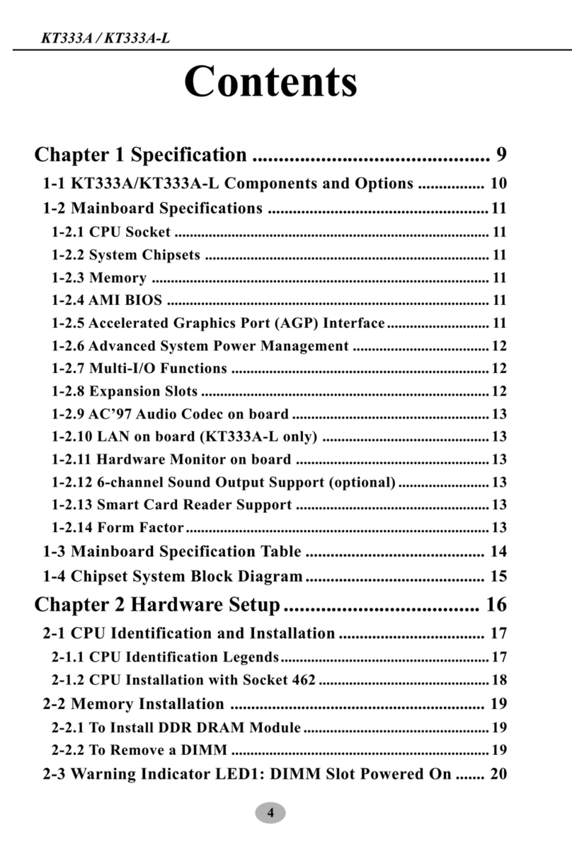
C NTENT
Chapter 1 Specification ............................................................ 8
1-1 Mainboard Specifications .........................................................9
1-1.1 CPU Socket .................................................................................... 9
1-1.2 Sysem Chipset Architecture ........................................................... 9
1-1.3 Memory .......................................................................................... 9
1-1. AWARD BIOS V6.0 ....................................................................... 9
1-1.5 Hardware Monitoring ..................................................................... 9
1-1.6 Sound Controller .......................................................................... 10
1-1.7 Multi-I/O Function ....................................................................... 10
1-1.8 Expansion Slots ............................................................................ 10
1-1.9 Accelerated Graphics port (AGP) Interface ................................. 10
1-1.10 FORM FACTOR ........................................................................ 10
1-1.11 Power Management .................................................................... 11
1-2 MainBoard Layout ................................................................. 12
1-3 Chipset System Block Diagram ............................................ 13
Chapter 2 Hardware Setup .................................................... 15
2-1 Pentium CPU Installation with Socket 78 ...................... 16
2-2 Pentium CPU Fan Installation: .......................................... 17
2-3 Memory Installation ............................................................... 18
2-3.1 To Install DIMM Module ............................................................. 18
2- AGP X (Accelerated Graphics Port) Installation............. 19
2-5 HDD/FDD Installation ........................................................... 20
2-6 Jumper and Switch Settings .................................................. 22
2-6.1 Switch 1 CPU Clock Select......................................................... 23
2-6.2 Factory Test (By JP5) ................................................................... 2
2-6.3 JBAT1 Clear CMOS ..................................................................... 2
2-7 Other Connectors Configuration ........................................... 25

5
Content
2-7.1 On Board FAN Connectors (FAN1,FAN2, FAN3) ...................... 25
2-7.2 WOL1 Wake On LAN .................................................................. 26
2-7.3 CD-ROM Audio Connector (CD1/CD2) ..................................... 26
2-7. Thermal Sensor Connector (RT2) (Optional)............................... 27
2-7.5 Complex Header NJ1 ................................................................... 28
2-7.6 ATX Power Supply Connectors version 2.03 for Pentium ........ 30
2-7.7 USB Header (Header USB1) ....................................................... 31
2-7.8 PS/2 Mouse And PS/2 Keyboard ................................................. 31
2-7.9 Chassis Panel Connector .............................................................. 32
2-8 IRQ Description ..................................................................... 33
Chapter 3 Software Setup ...................................................... 35
3-1 Open up the Support CD and choose Drivers and Utilities 36
3-2 Install “Intel Chipset Software Installation Utility”............ 37
3-3 Install “Intel Application Accelerator” ................................. 38
3- AC’97 Audio Driver Installation........................................... 0
3-5 Install Hardware Monitor Utility .......................................... 1
3-5.1 Installation ................................................................................... 1
3-5.2 Verification .................................................................................. 2
Chapter 4 BI S Setup............................................................ 44
-1 About BIOS Setup .................................................................. 5
-2 To run BIOS Setup ................................................................. 5
-3 About CMOS .......................................................................... 5
- The POST ( Power On Self Test ) ......................................... 5
-5 To upgrade BIOS .................................................................... 6
-5.1 Before Upgrading BIOS ............................................................... 6
-5.2 Upgrade Process ........................................................................... 6
-6 BIOS Setup --- CMOS Setup Utility .................................... 9
-6.1 CMOS Setup Utility ..................................................................... 9

85SID
6
-6.2 Standard CMOS Setup ................................................................. 50
-6.3 Advanced BIOS Features ............................................................. 53
-6. Advanced Chipset Features .......................................................... 57
-6.5 Integrated Peripherals................................................................... 60
-6.6 Power Management Setup............................................................ 66
-6.7 PNP / PCI Configuration .............................................................. 70
-6.8 SmartDoc Anti-Burn Shield ......................................................... 72
-6.9 Frequency/Voltage Control .......................................................... 7
-6.10 Load Optimized Default ............................................................. 77
-6.11 Set Supervisor / User Password.................................................. 78
-6.12 Save & Exit Setup ...................................................................... 79
-6.13 Exit Without Saving ................................................................... 79
Appendices .............................................................................. 81
Appendix-1 Identifying BIOS version and BIOS part Number 82
Appendix-2 Identifying Mainboard model Number ................. 83
Appendix-3 Technical Terms ....................................................... 8

7
Content
Mainboard
Support CD
Bundled Bonus Pack CD
Bundled Bonus Pack Manual
Temperature Sensor Cable
ATA66/100 DE Cable (Optional)
RS232 Cable
FDD Cable
User’s Manual
ITEM LIST CHECKUP

8
85SID
Chapter 1 Specification
• This chapter introduces the characteristics of this series of mainboards.
t includes the information on the chipset, CPU types, built-in functions
and layout. Users will have more ideas about this powerful series after
reading this chapter.
The topics contained in this chapter are:
1-1 Mainboard Specifications
1-2 Mainboard Layout
1-3 Chipset Diagram
Introduction

9
Chapter 1 Specification
1-1.1 CPU Socket
• CPU Socket 478B on board, supporting ntel® Pentium 4 and Northwood
processors in the 478-pin package for 400MHz System Bus.
1-1.2 Sysem Chipset Architecture
• NTEL 845 Chipset Memory Control Hub (MCH):
To work with ntel Pentium 4 Processor for managing and arbitrating
between 4 interfaces:
-- the System Bus (Host nterface);
-- the memory nterface;
-- the AGP Port and the Hub nterface;
• MCH Clockings:
-- Asynchronous;
-- System Bus target speed at 400MHz;
-- AGP and Hub nterface constantly at 66MHz base;
• ntel CH2 Chipset (Second generation /O Controller Hub):
Communicating with ntel 845 by the Hub interface at 66MHz/266MB/s;
-- Transmitting nterrupt related messages;
-- Transmitting Power management events;
-- Transmitting SM , SC , SERR indication messages;
1-1.3 Memory
3pcs of D MM on board for single / double sided D MMs, supported by
3.3V default voltage:
• ntel 845 MCH directly supporting one channel of SDRAM up to 3GB
capacity.
1-1.4 AWARD BI S V6.0
• Supporting Plug & Play V1.0.
• FLASH MEMORY for easy upgrade.
• Supporting B OS writing protection.
• Year 2000 compliant.
1-1.5 Hardware Monitoring
• Programmable control, status, to provide monitoring and alarm for flexible
desktop management of hardware temperatures. Utility Software is
enclosed in Support CD to help display monitoring statuses of:
9 positive voltages, 2 types of hardware temperatures, 3 Fan speeds;
1-1 Mainboard Specifications

10
85SID
1-1.6 Sound Controller
• SoundBlaster Pro Hardware and Direct Sound Ready AC97 Digital Audio
Controller with Codec onboard.
1-1.7 Multi-I/ Function
• ntegrated DE Controller, supporting:
-- 2x Ultra ATA100 / 66 / 33 Connectors
-- Two UARTs for Complete Serial Ports (2x COM ).
• Dedicated R Connector:
-- Third serial port dedicated to R function either through the two complete serial
ports or the third dedicated port nfrared- rDA (HPS R) and ASK (Amplitude Shift
Keyed) R.
• Multi-mode parallel connector:
-- Standard mode, ECP and EPP support.
• Floppy Disk connector:
-- One FDD connector with drive swap support.
• Universal Serial Bus connector:
-- USB V1.1 compliant.
-- 2 built-in USB connectors and one USB Header (USB1) which requires an
optional USB cable to provide 2 more optional USB ports.
• PS/2 Keyboard connector.
• PS/2 Mouse connector.
1-1.8 Expansion Slots
• Three PC bus Master slots.
• One AGP 4x mode slot.
• Three D MM slots.
1-1.9 Accelerated Graphics port (AGP) Interface
One AGP slot on board is supported by the ntel 845 Chipset MCH AGP
nterface in 1.5V mode (with AGP voltage selectable in B OS Setup):
• AGP v2.0 compliant.
1-1.10 F RM FACT R
• ATX form factor.
• This mainboard is compatible with both ATX Power Supply Version 2.03
(with +12V Power Connector) and the older ATX Power Supply (with
Peripheral Power Connector).
• Mainboard size: 24.5cm x 22.0cm.

11
Chapter 1 Specification
1-1.11 Power Management
• ACP 1.0B compliant (Advanced Configuration and Power nterface).
• APM V1.2 compliant (Legacy power management).
• Supporting ACP suspend and POS mode (Power On Suspend).
• System event monitoring with two event classes.
• Supporting Wake On LAN (WOL) & Wake On Modem.
• Supporting real time clock (RTC) with date alarm, month alarm, and
century field.

12
85SID
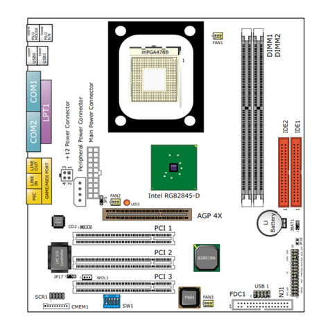
1-2 MainBoard Layout
PCI 1
PCI 2
PCI 3
Intel RG82845
DIMM1
DIMM2
DIMM3
LPT1
COM1COM2 PS/2
MOUSE
PS/2
K/B
upper
lo er
USB1
USB0
upper
lo er
1
Peripheral Po er Connector
+12 Po er Connector
Main Po er Connector
AC'97
Codec
Intel RG82845
AGP4X
82801BA
FWH
SW1
DIP
1 2 3 4 5
LPC I/O
Controller
USB1
116
Li
Battery
1
1
1
FDC
Clock
Generator
NJP1
SPEAK RST KEYLOCKPWR/LED SUS_LED
IDE_LED IR PWR SMI
30
1
++
--
+-
FAN3
1 3
FAN2
1 3
FAN1
1 3
JBAT1
1 3
WOL1
1 3
CD1
CD2
1 4
1 4
RT2
JP5
1 3
IDE2
IDE1
1
mPGA478B
MIC
GAME/MIDI PORT
LINE
OUT
LINE
IN
MIC
LED2

13
Chapter 1 Specification
ntel 82845MCH + CH2 Chipset Diagram
1-3 Chipset System Block Diagram
System
Memory
PCI
Agent
Super
I/O
PC133 SDRAM
1.06GB/s
FWH
(Firm are Hub)
ICH2
(I/O Controller Hub)
Intel 82845
MCH
-System Bus
-Memory Controller
-AGP Controller
-Hub Interface
PCI Bus
GPIO
System Bus (4x100MHz)
Band idth 3.2GB/s
4 USB Ports
4 IDE Drives
Ultra DMA100/66
PCI Slots
Audio Codec(s)
LAN Connect
Intel Pentium 4 Processor
AGP Graphics
Controller
AC'97 2.1
LPC I/F
Memory
Interface
AGP 4x
(1.5V)
1.06GB/s
Keyboard
Mouse,FD,
PPSP,IR

14
85SID
M
e
m
o

15
Chapter 2 Hardware Setup
To Get things ready for Hardware setup !!!
1. We recommend to install your CPU before any other componentes. For
detailed installalation instructions of processor, you can also refer to the
pamphlet enclosed in your CPU package.
2. nstalling a cooling fan with a good heatsink is a must for proper heat
dissipation for your CPU. Get ready an appropriate fan with heatsink for
proper installation. nproper fan and installation will damage your CPU.
3. n case CPU Vcore, CPU clock or Frequency Ratio is adjustable onboard,
please follow the instructions described in the User manual for proper
setup. ncorrect setting will cause damage to your CPU.
The following topics are included in this chapter:
2-1 Pentium 4 CPU Installation
2-2 Pentium 4 CPU Fan Installation
2-3 Memory Installation
2-4 AGP 4X (Accelerated Graphics Port) Installation
2-5 HDD/FDD Installation
2-6 Jumper and Switch Settings
2-7 Other Connectors Configuration
2-8 IRQ Description

16
85SID
2-1 Pentium 4 CPU Installation with Socket 478
This series of mainboards are built with CPU Socket 478 (with 478 pins)
supporting the ntel Pentium 4 CPU:
• Follow the steps described in this section to install the 478-pin Pentium 4 CPU
into the on board Socket 478.
• After installation of Pentium 4 CPU, you must also install the specific Pentium 4
CPU fan designed in tandom with this CPU. This CPU Fan installation is
described in next section.
mPGA478B
ntel Pentium 4
3 Make sure that all CPU pins have
completely entered the socket
and then lower down the lever to
lock up CPU to socket.
mPGA478B
ntel Pentium4
2 Configure Pin 1 of CPU to Pin 1 of
the Socket, just as the way shown
in the diagram on the left. Adjust
the position of CPU until you can
feel all CPU pins can get into the
socket with ease.
mPGA478B
Pin 1
1 First pull sideways the lever of
Socket 478, and then turn it up
90-degree so as to raise the
upper layer of the socket from the
lower platform.

17
Chapter 2 Hardware Setup
2-2 Pentium 4 CPU Fan Installation:
Connect to CPU
FAN connector
Press down 4 latches to
lock fan to fan socket
Pentium 4 Fan Socket
Fan Connector

18
85SID
2-3 Memory Installation
2-3.1 To Install DIMM Module
• This series of mainboards only supports SDRAM up to 3GB capacity
with 3 D MM sockets on board. Do not insert other type of modules into
these sockets. EDO & FTP DRAM are not supported by this mainboard
either.
• D MM has 168-pins and two notches. nsert a D MM vertically into the
D MM socket with each notch matching the one in the socket. Press the
D MM down in a gradual way until it surely reaches the bottom and clicks
straight up the two latches on the left and right of the socket.
How to tackle with the memory Modules:
• Make sure to unplug your power supply before adding or removing memory
module. Failure to do so may cause severe damage to both your mainboard
and the memory module.
• Pay attention to the orientation of the D MM slots. Forcing a D MM in a
socket improperly will damage the memory module and socket.
• Make sure you have the right type of memory module for your mainboard.
168-Pin DIMM Notch Key Definitions(3.3V)
DRAM Key Position Voltage Key Position
Unbuffered 3.3V
Key Point: Press the module down gradually until it has totally
reached the socket bottom and clicked up both two socket latches
completely. f any one of the latches has not turned up completely,
you should unplug the module and press it down the socket a bit
more firmly.

19
Chapter 2 Hardware Setup
2-4 AGP 4X (Accelerated Graphics Port) Installation
AGP Accelerator
AGP4X
4X notch
Warning:
• The AGP 4X slot on board supports solely 4X AGP card configuration.
User should not insert 1X / 2X AGP card to this mainboard.
• LED2 AGP Protection ndicator is on board this series. n case inappropriate
AGP card (such as AGP 2X) is inserted into this AGP 4X Slot, LED2 will
light up to warn that AGP installation is inproper. The wrong AGP card
should be replaced; otherwise system cannot be booted.
Card Latch
PCI 1
PCI 2
PCI 3
Intel RG82845
DIMM1
DIMM2
DIMM3
LPT1
COM1COM2
PS/2
MOUSE
PS/2
K/B
upper
lo er
USB1
USB0
upper
lo er
1
Peripheral Po er Connector
+12 Po er Connector
Main Po er Connector
AC'97
Codec
Intel RG82845
AGP4X
82801BA
FWH
SW1
DIP
1 2 3 4 5
LPC I/O
Controller
USB1
116
Li
Battery
1
1
1
FDC
Clock
Generator
NJP1
SPEAK RST KEYLOCKPWR/LED SUS_LED
IDE_LED IR PWR SMI
30
1
++
--
+-
FAN3
1 3
FAN2
1 3
FAN1
1 3
JBAT1
1 3
WOL1
1 3
CD1
CD2
1 4
1 4
RT2
JP5
1 3
IDE2
IDE1
1
mPGA478B
MIC
GAME/MIDI PORT
LINE
OUT
LINE
IN
MIC
LED2
LED2
AGP Protection ndicator

20
85SID
PCI 1
PCI 2
PCI 3
Intel RG82845
DIMM1
DIMM2
DIMM3
LPT1
COM1COM2
PS/2
MOUSE
PS/2
K/B
upper
lo er
USB1
USB0
upper
lo er
1
Peripheral Po er Connector
+12 Po er Connector
Main Po er Connector
AC'97
Codec
Intel RG82845
AGP4X
82801BA
FWH
SW1
DIP
1 2 3 4 5
LPC I/O
Controller
USB1
116
Li
Battery
1
1
1
FDC
Clock
Generator
NJP1
SPEAK RST KEYLOCKPWR/LED SUS_LED
IDE_LED IR PWR SMI
30
1
++
--
+-
FAN3
1 3
FAN2
1 3
FAN1
1 3
JBAT1
1 3
WOL1
1 3
CD1
CD2
1 4
1 4
RT2
JP5
1 3
IDE2
IDE1
1
mPGA478B
MIC
GAME/MIDI PORT
LINE
OUT
LINE
IN
MIC
LED2
• To install HDD (Hard Disk Drive), you may connect the connector of DE
cable to the primary ( DE1) or secondary ( DE2) connector on board, and
then connect the gray connector to your slave device and the black
connector to your master device. f you install two hard disks, you must
configure the second drive to Slave mode by setting its jumpers correctly.
Please refer to your hard disk documentation for the jumper settings.
Hard Disk Drive Connector:
Orient the red line on the DE
ribbon cable to Pin1.
2-5 HDD/FDD Installation
Gray connector
Blue connector
IDE Cable
Black connector
red line
Table of contents
Other SOLTEK Motherboard manuals

SOLTEK
SOLTEK SL-65MIE User manual

SOLTEK
SOLTEK SL-65EB User manual

SOLTEK
SOLTEK SL-67EZ Use and care manual

SOLTEK
SOLTEK 85MR3 User manual

SOLTEK
SOLTEK SL-85ERV4-R User manual

SOLTEK
SOLTEK SL-75DRV2 User manual

SOLTEK
SOLTEK 65kv User manual

SOLTEK
SOLTEK SL-65EP User manual

SOLTEK
SOLTEK B7A-F User manual

SOLTEK
SOLTEK SL-55D5 Use and care manual

SOLTEK
SOLTEK 75FRV User manual

SOLTEK
SOLTEK SL-65KVB User manual

SOLTEK
SOLTEK SL-61A Use and care manual

SOLTEK
SOLTEK SL-67B-W User manual

SOLTEK
SOLTEK SL-65KV2-T User manual

SOLTEK
SOLTEK 85ERV2 User manual

SOLTEK
SOLTEK SL-B9D-FGR User manual

SOLTEK
SOLTEK 85DIR User manual

SOLTEK
SOLTEK SL-B8D-F User manual

SOLTEK
SOLTEK SL-65MIV-C User manual