SOMMY CN Series User manual

1.CodeIllustration
CN -R C
Display digit
6
6digits
Control output:R:RelayoutputS:Solidstaterelayoutput
CN Seriesmulti-functioncounter
Alarmoutput:B:oneC:two
*24Vpowersupplycouldbeordered
Communication function:0:withoutcommunication8:RS485communication
Powersupply:Blank:100-240VAC/DC F:24VDC powersupply
Dimension(mm):4:48H 48W 101L 7:72H 72W 100L 8:48H 96W 100L
80:80H 160W 102L
Foryoursafety,pleaseread the belowcontentcarefullybeforeyou usethe meter!
SafeCaution
Pleasecomplywiththebelowimportantpoints:
WarningAnaccident mayhappeniftheoperation doesnotcomplywiththeinstruction.
NoticeAnoperationthat doesnot complywiththeinstructionmayleadtoproduct damage.
The instruction of the symbolinthe manualisasbelow:
Anaccidentdangermayhappen inaspecialcondition.
Warning
1. Asafetyprotectionequipmentmust beinstalledorpleasecontact withusfortherelativeinformationiftheproductisusedunder
thecircumstancesuchasnuclearcontrol,medicaltreatmentequipment,automobile,train, airplane, aviation,entertainmentorsafety
equipment, etc. Otherwise, itmaycauseseriousloss,fireorpersoninjury.
2. Apanelmust beinstalled, otherwiseit maycausecreepage(leakage).
3. Donottouchwireconnectorswhenthepowerison,otherwiseyoumaygetanelectricshock.
4. Donotdismantleormodifytheproduct, Ifyouhavetodo so,pleasecontactwithusfirst.Otherwiseit maycauseelectricshock
andfire.
5. Pleasechecktheconnectionnumberwhileyouconnect the powersupplywireorinput signal,otherwiseitmaycausefire.
.
Caution
1.Thisproduct cannot be usedoutdoors.Otherwisetheworkinglifeoftheproductwillbecomeshorter, oranelectricshock accident
mayhappen.
2. Whenyouconnect wiretothepowerinput connectororsignalinput connectors, themoment of theNo.20AWG(0.50 mm2)scrwew
tweakedtotheconnectoris0.74n.m-0.9n.m. Otherwisetheconnectorsmaybedamagedorgetfire.
3. Pleasecomplywiththeratedspecifications. Otherwiseitmaycausefireaftertheworkinglifeof the product becomesshorter.
4. Donotusewateroroilbasecleanertocleantheproduct. Otherwiseit maycauseelectricshockorfire,anddamagetheproduct.
5.Thisproduct shouldbeavoidworkingunderthecircumstancethatisflammable, explosive,moist,undersunshine, heat radiationand
vibration.
6. Inthisunitit mustnothavedust ordeposit, otherwiseit maycausefireormechanicalmalfunction.
7. Donotusegasoline, chemicalsolvent tocleanthe coveroftheproductbecausesuchsolvent candamageit. Pleaseusesomesoft
clothwithwateroralcoholtocleantheplasticcover.
MMeter/Yardconvertfunction
:
Meter/Yardswitchfunction
CNSeriesMulti-function counterCN SeriesMulti-functionCounterUser’sManual
KKCNE01A-1
Features:
⊙Maxcountingspeedcanreach10KCPS
⊙Coefficient besettableamong0.00001~999999
⊙Universalinput.“NPN”or “PNP”isselectedbysoftware
⊙Atmost twoloopsof alarmforcounting/lengthcounting
oneloopofalarmforbatchcounting
⊙
⊙WithRS485communicationfunction,standardModbus
RTUprotocol
⊙Canbeappliedtothecounting/controllinginthefieldof
lightindustry、machinery、packing、foodindustry,etc.
PS2:Settingvalueof OUT2being displayedon the below LED
Reset key
Batchsettingkey
Functionkey Parametermodifykey
PS1:Settingvalueof OUT1being displayedon the below LED
BA.S:TheaboveLED displaysbatchcountingvalue
The below LED displaysthebatchsetting value
KKCNE01A-2
Code Panelsize
(mm)
No.
2.OrderingCode
3.TechnicalParameter
Series
Display
Powersupply
Input pulsewidth
Input
One-shot output
Control output Contactscapacity
SSR capacity
Memorytime
Externalsensorpower
Workingtemperature
Shock
Dualrowswith6-digit LED
90-110%oftheratedvoltage(AC)
Input frequency of INA,INB
INA,INHIBIT,RESET,BATCH RESET,1msor20ms canbeselected
Voltageinput:Input impedanceis5.4KΩ,“H”:5-30VDC “L”: 0-2VDC
Non-voltageinput Maxshort-circuitimpedance: 1KΩ,
Residualvoltage Max2VDC Open-circuitimpedance Max100KΩ
10/50/100/200/500/1000/2000/5000ms
NO:250VAC3AimpedanceNC 250VAC2Aimpdance
Max30VDC ,Max100mA
10years
12VDC±10%below100mA
-25℃~65℃(Non-freezing)
35-85%RH
Min100MΩ(at 500VDC)
2000VAC50/60Hz1minute
300/S(About:30G)eachdirectionof X,Y,Z for3times
Above10,000,000times
Above100,000times(NO:250VAC3AloadNC:250VAC2Aload)
4.PanelIndication
CN8-RC68 6
Alarmoutput
100-240VAC/DC
1Hz,30Hz,1KHz,5KHz,10KHzcanbe selectable
CN8-RC60 48H×96W
6
21Relay
1Relay
1Relay
Nobatch
48H×96W
CN80-RC68 6
2
CN80-RC60 80H×160W
6
2
RS485
NO
RS485
NO
NO
RS485
NO
80H×160W
OUT1,OUT2:OUT1orOUT2output indicate
BA.O:Batchoutput indicate(CN4without thisindicatelight)
LOCK: Keylock indicator
CN4-RC60
CN7-RC60
CN7-RC68
Communication
2
2
2
2
CN
1
2
3
4
5
6
7
Displaydigit Batchoutput
1Relay
1Relay
1Relay
Allowablevoltage floating range
-10℃~50℃(Non-freezing)
Storetemperature
AmbientHumidity
Insulationresistance
Dielectricstrength
Interference(ACPower) ±2kVinterferencedbysquarewavegenerator(Pulsewideth:1us)
Vibration Mechanical
Malfunction
Amplitude:0.75mmFrequency: 10to55HzeachdirectionofX, Y, Zfor1hour
Amplitude:0.5mm Frequency: 10to55Hzeachdirectionof X,Y,Z for10min
Mechanical
Malfunction
LifeSpan Mechanical
Electric
100/S(About:10G)eachdirectionof X,Y,Z for3times
CN7SERIES COUNTER

BA MD
Measuring status Batchsetting value modifying status
key key
KKCNE01A-3
5.OperationSequecy
6.Batchcounting&batchsettingvalue
Batchreset
Batchsettingvalue
0
Batchoutput
6.1.Batchoutput action
◆Batchcounting
Batchcounting valueisupcounting ,onlyexternalresetsignalcanclearit tozero.
Ifbatchcountingvalue beyond999999,itwillresetautomaticallyandstartcountingagain .
Thefirstbatchcountingvaluearenotinfluencedbykeyandexternalreset signal .
(1)Batchcountingundercountingmode
WhenthecountingalarmoutputNo.equalstothe batchsettingvalue, batchalarmwilloutput .
Whenbatchcontroloutput isused, theintervalsoftheupcounting timeshouldmorethan10ms .
7.Coefficient Function
◆Output actionforbatch
If thebatchoutputisON,itwillkeep theONstatustill thebatchreset signalcomes.
If thebatchoutputisON,andthemeterpoweroffthenonpoweragain,batchoutput shouldkeep “ON”statustill externalresetsignalcomes.
6.2.Modifying forthebatchsetting value
The diameterof thewheelwhichconnectsthe rotarycoderis22mm,
whenthe rotaryencoderrotatesacircle,therewillbe 1000 pcspulses
CN7SERIESCOUNTER
CN7SERIES COUNTER CN7SERIESCOUNTER
CN7SERIESCOUNTER
Eg:PulseNo.-- Pisthe pulsequantitywhentherotaryencoderrunningacircle,Listhemeasuredlength,coeffecient value=L/PulseNo.of
onecircle, It representstheactuallengthofapulse.
1.Howtochangethevaluefrom175to180
(1)(2)
(4)
(3)
Onmeasuringstatuspressto
enterthe settingvaluemodifystatus
press againtomake“5”flick
Press
change “5”to “0”。
or 5times
Goontopress , andselect “7”
thenmakeitflick MD
Pressonce,change “7”to “8”
press toconfirmandreturnto
measuringstatus.
∴Undermeasuringstatuspresstoenterthesettingvaluemodifystatus. andtheselecteddatawill flickfromright toleft circularly
RST
BA
Ifenterthebatchvaluesettingstatus, andwithout anyoperationformorethan60s, itwillreturntomeasuringstatusautomatically.
MD
旋转编码器
刀具
滚轮
电机
计数器和旋转编码器控制长度
π×滚轮的直径( D)
系数值 = ------------------------
编码器旋转一周的脉冲个数
这个连接编码器的滚轮直径为22mm.编码器旋转一周的脉冲数为1000pcs
电机控制系统
计数器
π×Diameter( D)
Coefficient value = ------------------------
Pulsequantityof theencoderrotating acircle
Underfunction setting mode ,change the coefficient value to0.069inthecoefficientsetting menu
3.1416×22
= ------------------
1000
= 0.069mm/pulse
Undermeasuringstatus, press keytoenterthebatchsettingvaluemodifyingstatus
Thewayof modifyingthe batchsettingvalueisthesameasthat of thecountingsettingvalue.Presstoselect thedigit which
needstobemodifiedandmakeit flick . Press tomodifythevalue. Presstoconfirmandreturntomeasuring status.
Whenthebatchsettingvaluemodifyingstatus,theaboveLEDwilldisplaythepresent batchcountingvalue.
Controllinglengthofthecounterandrotaryencoder
Rotaryencoder
Motor
Motorcontrolling system
Wheel Cutter
Counter
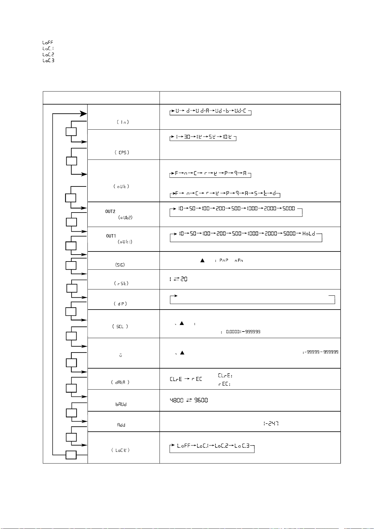
9.Settingforthe Counting Mode
KKCNE01A-4
()
Startvalue
Countingvaluestorage
Settingmode Selction (、▲)
MD
※
※Up/Down-A、B、Cinputmode
or
Unit:ms
Unit:ms
→
-- -- - -→-- - -- - →-- - -- - →- -- - --
(Unit:ms)
MD
MD
MD
MD
MD
MD
MD
MD
MD
MD
▲
MD
▲
Poweroff Thecounting valuereset
Maxcountingspeed
Inputmode
Minreset time
Lockkey
Decimalpoint
output time
8.Settingforthe keylocking
** *
()
Baudrate
Addressofthemeter
()
MD
▲
▲
Modifythecoefficientvaluekey
Coefficient valuerange
RSTkey:Modifythe decimalpoint of coefficient value
▲
▲
key: changethestartvalue Startvalue setting range
Startvalue:Thedisplayedvalueatferresetautomaticallyormanually
MD
Ifthe modeisS TD,inputmodecanonlyselectUd-A BC
output
Countingspeedmeansthemaxinputfrequencyof INAandINB, to
5K theinputfrequencybeyond5K,thenmeasuringwillbe supposeit to
,if notaccuracy.
Outputmode
UporDowninputmode
output time
Input logic Selectwith , inputmode
oefficientvalue
Minwidthof RESETsignal
key: Movetheflick digit
C
key: Movetheflickdigit
Poweroff Thecounting valuebe saved
Baudratebeselectable:4800or9600
Communicationaddresscanbesettable:
Keylockistoavoidmistakeoperationofthekey
(LOCKOFF):Cancelkeylock
(LOCKLEVEL1):LockRST key
(LOCKLEVEL2):Lock ,
(LOCKLEVEL3):LockRST,
▲
▲
▲
▲
,▲and
▲
and key
KKCNE01A-5
※Infunctionsettingmode,if without anyoperationformorethan 60s,thecounterwillreturntomeasuringmode.
※If selectmodeF ormodeN,whencountingvaluereachesthepresetvalue,theoutputwillmaintain,sothereisno “output timeofOUT2”
menuinfunctionsettingmode
※If outputmodesettoS、T、D ,inputmodecanonlyselectUd-A、B、C.If want toselect Up/Downinput mode,thenoutput modecanjust
selectthemodeexceptforthemodeS、T、D.
※Ifselectmode Dasoutputmode,when the counting frequencybeyond 1Kcps,consideringthe responding timeofarelaymaycauseabnormal outputaction,
soSSR output willbe better.
※WhenMaxcountingspeedis5kcpsor10kcps,ifchangethemode tomode“D”,countingspeedwillselect 1KCPSautomatically.
※Infunctionsettingmode,externalinputsignalcanalsoberecognized. whenexitthe functionsettingmode,displayvalueandoutputwill resetautomatically.
※Whenthestartvalue(W)exceedsthesettingvalueofOUT1andOUT2, therewillbenooutput of OUT1andOUT2.
10.ActionModeSwitch
Measuringmode(countingstatus)
Input Mode(IN)
Maxcounting speed(CPS)
Output mode(OUT)
Output time (OUT2)
Outputtime (OUT1)
Prescalevalue(SCL)
Input logic (SIG)
Minreset time(RST)
Decimalpoint(dP)
Startvalue(W)
Functionlockkey(LOCK)
MD
MD
MD
MD
MD
MD
MD
MD
MD Press3s
Counting value storage(DATA)
Addressofthe meter(ADD)
MD
MD
Baud rate(BAUD)
MD
MD
MD
MD
U
(Up)
D
(Down)
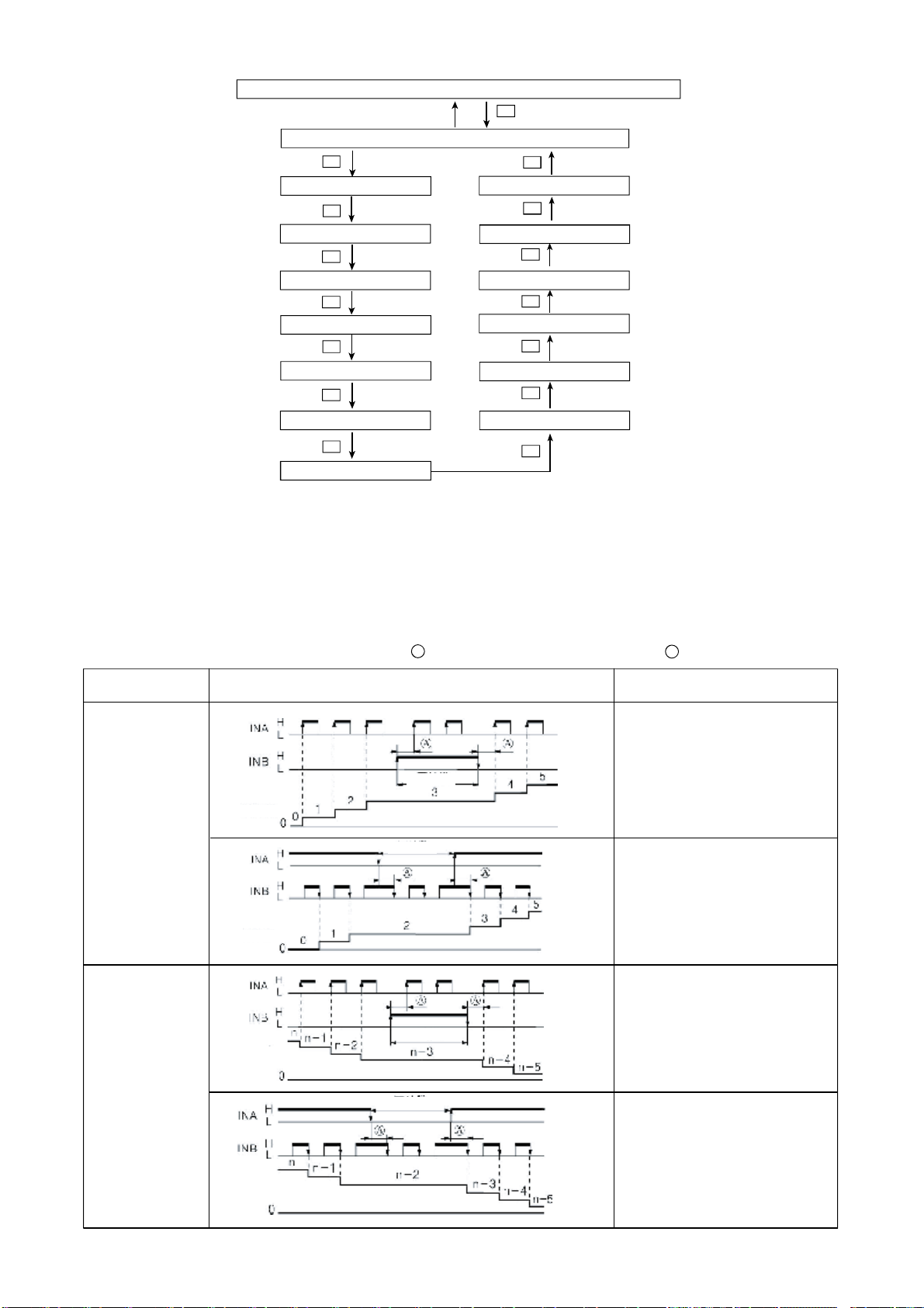
Input mode Countinggraph Remark
※A :B :
Beyondthewidthof the minsignal
Beyondthehalf of theminsignalwidth
INA:
INB:
INB=L:
INB=H ForbidINAtocount
INA
INB
INA=H:
INA=L:ForbidINBtocount
INA
INB
INB=L
INB=H:ForbidINAtocount
INA
INB
INA=H:
INA=L:ForbidINBtocount
11.Input actionmodeof thecounter
Beusedascountinginput
Nocounting
Counting value
Nocounting
Nocounting
Nocounting
Counting value
Counting value
Counting value
Beusedascontrolinput
InputpulsetoINA,thencountingup
Beusedascountinginput
InputpulsetoINB,thencountingup
Beusedascountinginput
Beusedascontrolinput
Inputpulseto INA,thencountingdown
Beusedascontrolinput
Beusedascontrolinput
Beusedascountinginput
Inputpulseto INB,thencountingdown

KKCNE01-A/0-6
Inputmode
Up Down
F
N
C
R
12.
Up/DownA,B,C
One-shot output(OUT1output)
Holdoutput One-shot output
(OUT2output)Holdoutput Output at thesametime
Reset
999999
SV2
SV1
Display
OUT1
OUT2
0
Reset
999999
SV2
SV1
Display
OUT1
OUT2
0
(OUT)
Reset
999999
SV2
SV1
Display
OUT1
OUT2
0
(OUT)
Reset
999999
SV2
SV1
Display
OUT1
OUT2
0
(OUT)
(OUT)
Outputmode
Actionforcounting /timing whenit
reachestothesettedvalue
Displaykeepsupordown,
outputmaintaintillresetsignalinput
Bothdisplayandoutputmaintaintill
resetsignalinput .
Displayvalereturntothebeginning
statusautomatically,outputwon’
t
returntothebeginninguntillitreaches
tothesetteddelaytime.
(Outputactionisrepeated)
Bothdisplayvalueandoutputmaintain
tillitreachestothesetteddelaytime
thenreturntothebeginningstatus.
(Outputactionisrepeated)
※
Sign Input type
H
L
Voltageinput(PNP)
5-30VDC
0-2VDC
Contactsinput(NPN)
Opencircuit
Shortcircuit
Input mode Countinggraph Remark
INA:
INB:
INB=L:
INB=H:
Ud-a
(Up/Down-A)
Orderinput
Ud-b
(Up/Down-B)
Singleinput
Ud-c
Phasedifferenceinput
※starevalue=0
Counting value
Counting value
Counting value
Beusedascountinginput
Beusedascontrolinput
InputpulsetoINA,thencountingup
Inputpulseto INA,thencountingdown
InputpulsetoINA,thencountingup
InputpulsetoINB,thencountingdown
INAleadaheadINB,thencountingup
INAlagbehindINB,thencountingdown
Phasedifferenceinput (be applied to
rotaryencoder)
WhenusephaseAandphaseBoftherotaryencoder,pleasetakeINAandINBasinputends,andselect Ud-Cinputmode.

KKCNE01A-7
Up/DownA,B,C
S
T
D
Action
SV2
SV1
SV2
SV1
SV2
SV1
Inputmode
Up Down
K
P
Q
A
Up/DownA,B,C
Reset
999999
SV2
SV1
Display
OUT1
OUT2
0
(OUT)
Reset
999999
SV2
SV1
Display
OUT1
OUT2
0
(OUT)
Reset
999999
SV2
SV1
Display
OUT1
OUT2
0
(OUT)
Reset
999999
SV2
SV1
Display
OUT1
OUT2
0
(OUT)
Actionforcounting /timing whenit
reachestothesettedvalue
Displayvaluekeepsupordowntill
resetsignalinput ,output won’treturnto
thebeginningstatusuntilitreaches
thesetteddelaytime.
(Outputactionisrepeated)
Displayvaluemaintainstillthedelaytime
output, thendisplaythevalueofnext
round.(Counting/Timingofnextround
startsfromthebeginningvalueduring
thedelaytime)
(Outputactionisrepeated)
Displayvaluekeepupordown
during theoutputdelaytime,
whenitcomestothesetteddelay
time,boththedisplayvalueand
output willreturntothebeginning
status.
(Outputactionisrepeated)
DisplayvalueandoutputofOUT1maintain
tillresetsignalinput.OUT2returntothe
beginningstatuswhenitreachesto
theoutputdelaytime .
(Outputactionisrepeated)
OUT1andOUT2meetthe following
requirements keep ON statu
Displayvalue ≥Settingvalue1
Displayvalue ≥Settingvalue2
:
“”
OUT1keep ON “status
hendisplayvalue< Presetvalue1,
“
Whendisplayvalue< Presetvalue 2,
OUT2keep “oFF”status.
W
Onlywhendisplayvalue=Settingvalue
(presetvalue1or2),OUT1andOUT2
keep ON status
Whencountingspeedset to1kcps,
shoulduseSSRoutputmode .
“”.
13.Connecting Drawing
CN4 CN7

KKCNE01A-8
15.OutputConnecting
14.InputConnecting
+12V
5.4kΩ
OV
(CNSeries)
Counting speed:setting to1or30cps(counter)
Counter
⑵
+12V
5.4kΩ
OV
(CNSeries)
Counter
Sensor
※
※
+12V
5.4kΩ
OV
+12V
5.4kΩ
OV
(PNPVoltage input) (CNSeries)
※
Relayoutput
Counter
Load power
Load
SSRoutput
Counter
load power
(DC)
(+)
(-)
※
SSRoutput
1.Adoptproperload and power,outputoftheSSRcan’t be
too large,capacity(Within 30VDC.100mA)
2.Makesurethe powersupplynotconnected inversally
3.When adoptinductiveload (suchasrelay),
Filtercircuit(suchasdiode,rheostat)should be connected
between the two endsofthe load .
+12V
INA
GND
※
+12V
INA
GND
INA
GND
+12V
INA
Load
Note:Pleasesubject totheconnectingdrawingon theactualproductif anychanges
1、Input logic:No-voltageinput(NPN)
⑴Solidstaterelayinput
Standardsnesor:NPNoutputsensor
Tothe internalcircuit
(NPNNo-voltage input)
Contactsconnectingin
Tothe internalcircuit
2、Input logic:voltageinput(PNP)
⑴Solidstaterelayinput
Standardsensor:PNPoutput sensor
Sensor Counter
Tothe internalcircuit Tothe internalcircuit
⑵Contactsconnectingin
Counter
(CNSeries)
Counting speed:setting to1or30cps(counter)
16.Dimension &MountingSize
CN4:(48*48)
CN7:(72*72)
CN8:(48*96)
CN80:(160*80)
48
72
96
160
Code AH(Minimun)
G
B C D E F
J
48
72
48
80
101
100
100
102
10
10
6
10
91
90
94
92
45.5
68
91.5
154
25
25
25
30
45.5
68
45.5
76.5
45
67.5
45
76
K
(Minimun)
25
25
25
30
PanelsizeSide-facesizeMounting size
RemarkUnit (mm)tolerance+0.5%(Theparticularindicated arenotincluded)
A
B
C
E
D
F
G
K
J+0.5
-0
+0.5
-0 H
CN80

KKCNE01A-9
CommunicationProtocoloftheCounter
1.Typeand Format of theCommunicationData
Thedataframeformat of MODBUSRTUProtocolis: one startbit, 8databit ,without check, onestop bit .Baud rateofcommunication
transferdatais4800bit/sor9600bits/s
Dataflameformat
start bit databit check bit stop bit
1 8 without 1
2.TransterProcess of theCommunicationMessage
Whenthecommunicationorderbesenttothe slaveunit fromthe masterunit, ifthe slaveunit receiveoderwhichcoincideswiththe address
sent fromthe masterunitbecheckedCRC checkingand orderfromatwithout error,thenslaveunitwill carryoutthecorrespondingoperation
andfeedback therunningresult.
Aboutnormalresponse,theslaveunitjustfeedbackthereceivedfunctioncode . Whenit isabnormalresponse
,theslaveunitwill set the
highestbitofreceivedfunctioncodeto1,thenfeedback.
Functioncode
Definition Operation
0x03 Readregister Readthedataofsingleorseveral register
0x10 Writemulti-register
Itisincludeddataarea of the message, lengthofthedataisdifferentwithfunctioncode .
3.OrderFormat ofMasterUnit &Feedback MessageFormat fromSlaveUnit
Read Multi-register
Oderformat
Masterunit sendorder
Addressarea
Meteraddress 0X01 Meteraddress
0X01
Functionarea
Functioncode 0X03 0X03
Dataarea
Addressofthe
beginregister
High bit
0X00 ByteNo. of thedata 0X04
Lowbit
0X05 OUT2
0XC0
Quantityof
readregister
High bit
0X00 0X5A
Lowbit
0X01 0XFB
errordetect
area
CRCchecking
code
Lowbit
0X94 0X34
High bit
0X0B
errordetect
area CRC
checking
code
Lowbyte 0XA4
High byte 0XC7
Note
Theaboveexampleistoreadtheorderandformatofasingleregisterdata.Whenneedtoreadmultipleregistersatatime,
itonlyneedtofixthefirstadressof theregisterandthe needingreadregisterNo.s(read/writeorderfromlowbittohighbit ), then
canreadsuccessiveregisterdataof multipleaddress. Whenfeedbackadata,lowbitofitwillbeinfront, andhighbitlistsbehind.
3-2.WriteMulti-register
High bit 2
ThisseriesadoptAsynchronouscommunicationinterface(SCI),the electricallevelfortheinterfacecomplywiththestandardRS485protocol.
2-1.Addressof themeter(1byte)
Itisincludedintheaddress area,the rangeis:1-247.Themasterunit selectstheslaveunit byinput theslaveunit address toorderaddress
area. Whenthe slaveunit feedback adata,itput itsownaddress tothe addressarea of thefeeded backmessage, sothatthemasterunit
willlearnwhichslaveunit responsed . (Eachaddress oftheequipment inabusmustbeunique )
2-2.Functioncode(1byte)
Itisincludedinthefunctioncode of the message. When besenttoslaveunit fromthe masterunit, thefunctioncodewill telltheslaveunit
whichoperationsshouldbecarriedout .Whenslaveunitresponses, functioncodewill instructnormalresponseorerror(abnormalresponse).
Definitionof the functioncode
Writenpcsof 32-bit binarydataintonpcsof successiveregisters
2-3.Dataarea
3-1.
Forexample:Masterunitsendorderreading thedataofOUT2 alarmvalueregister
Message
format Feedbackmessagefromslaveunit
Addressarea
Functionarea Functioncode
Dataarea
register
data(32-digit
at behind)
data, lowbit
infront ,
bit high
Lowbit1
Lowbit2
High bit 1
KKCNE01A-10
Forexample
Masterunitsendsan orderwriting1000.000intoOUT2alarmregisteroftheslaveunit
Orderformat
Masterunit sends order
message
format
Feedbackmessagefromslaveunit
Addressarea
Meteraddress 0X01
Address area
Meteraddress 0X01
Functionarea
Functioncode 0X10
Function area
Functioncode 0X10
Dataarea
Addressofthe
beginregister
High byte
0X00 High byte 0X00
Lowbyte
0X05 Lowbyte 0X05
Readquantity
of theregister
High byte
0X00 Quantityof
writeregister
High byte 0X00
0X01 Lowbyte 0X01
ByteNo.softhe writedata
0X04
errordetect
area CRC
checking
code
Lowbyte 0X11
OUT2
registerdara
read towritein
Lowbit1
0X40 High byte 0XC8
Lowbit2
0X42
High bit 1
0X0F
High bit 2
0X00
CRC checking
code
Lowbyte
0X83
High byte
0X87
4.Communicationerroshooting
When the meterdetectsan errorexcepted forCRC checkingcode, it will feedback anerror message
tomasterunit .The slaveunitset thehigh bit of the received functioncode to1, then feedback the
meter address anderror codeaserrormessage
4-1.Errorcodeformatfeedback fromslaveunit
Address code
Function code (highest position)
Errocode CRC
checking code low byte
CRC
checking code low byte
one byte onebyte
onebyte
4-2.Errocode
0X01 Functioncodeerror Receivedfunctioncode can not besupportedbythemeter
0X02
Registeraddresserror
Receivedregisteraddressexceedstherangeof themeterregisteraddress
0X03
Quantityof registererror
Receivedregisterquantityexceedsregisterquantityofthemeter
0X04 Datavalueerror Receiveddatavalueexceedsthedatarangeof thecorrespondingaddress
5.Parameteraddress of themeter
No.
Registeraddress
Registername Datatype Valuerange
Function
Remark
0 0x0001 PV
Countingvalue long ----- R
Reserve3decimalpoint
1 0x0002 B
V
Batchcounting value
Unsigned long
----- R
2 0x0003 Alarmstatus Unsigned long
----- R
3 0x0004 OUT1alarmvalue (PS
1
)
Unsigned long
1~999999000 R/W
4 0x0005 OUT2alarmvalue (PS
2
)
Unsigned long
1~999999000 R/W
Reserve3decimalpoint
5 0x0006 BA.O (BA
.
S
)
alarmvalue
Unsigned long
1~999999 R/W
6 0x0007 SCL
scalecoefficient
Unsigned long
0.00001-9999.99
R/W
7 0x0008 W
Startvalue
long -99999-999999 R/W
Reserve3decimalpoint
8 0x0009 Meterstatus1 Unsigned long
----- R/W
9 0x000A
Meterstatus2 Unsigned long
----- R/W
10 0x000B Unsigned long
----- R/W
11 0x000C Unsigned long
----- R/W
*PV PS1 PS2
,aredefaultedtoreserve3decimalpoint. Theactualvalue=feedback dataorwritedata/1000.Ifthere
gisterfeedback
dataPV=1 ,actualPVvalue=0.001 .Similarly PS2register. Actualsettingvalueof OUT2
1000000into
write (PS2)=1000.0000
(EffectivedisplaydigitofthedecimalpointcanbesetbytheDPmenuof themeter)
errordetect
area
Addressofthe
beginregister
Dataarea
onebyte onebyte
Meterstatus3
Meterstatus4
Reserve3decimalpoint
Reserve5decimalpoint
(32-digit, lowbit
infront , highbit
at behind)
Lowbyte
,

KKCNE01A-11
0x0003
6.Alarmstatus(address )
Bit3
1
Bit3
0
Bit2
9
Bit2
8
Bit2
7
Bit2
6
Bit2
5
Bit2
4
Bit2
3
Bit2
2
Bit2
1
Bit2
0
Bit1
9
Bit1
8
Bit1
7
Bit1
6
Reservation BA.O alarmoutputflag
Bit1
5
Bit1
4
Bit1
3
Bit1
2
Bit1
1
Bit1
0
Bit
9
Bit
8
Bit
7
Bit
6
Bit
5
Bit
4
Bit
3
Bit
2
Bit
1
Bit
0
OUT2alarmoutputflag OUT1 alarmoutputflag
6-1、Bit0-Bit7OUT1 alarmoutputflag: 0x00 OUT1 0x01
noalarmoutput,OUT1 hasalarmoutput
6-2、Bit8-Bit15 OUT2 alarmoutputflag: 0x00 OUT2 noalarmoutput,0x01
OUT2 hasalarmoutput
6-3、Bit16-Bit23 BA.O alarmoutputflag:
0x00 BA.O noalarmoutput,0x01 BA.Ohasalarmoutput
1
7.Registerofthemeterstatus (address
0x0009)
Bit3
1
Bit3
0
Bit2
9
Bit2
8
Bit2
7
Bit2
6
Bit2
5
Bit2
4
Bit2
3
Bit2
2
Bit2
1
Bit2
0
Bit1
9
Bit1
8
Bit1
7
Bit1
6
OUT2outputdelaytimesettingunit OUT1 outputdelaytimesettingunit
Bit1
5
Bit1
4
Bit1
3
Bit1
2
Bit1
1
Bit1
0
Bit
9
Bit
8
Bit
7
Bit
6
Bit
5
Bit
4
Bit
3
Bit
2
Bit
1
Bit
0
OUToutputmodesettingunit SIGlogiclevelselectionforinput terminal
7-1、Bit0-Bit7 SIG 0x00-
inputlogiclevelselectunit(valuerange 0x01)
Bit0-Bit7=0x00 NPN
Bit0-Bit7=0x01 PNP inputmode,signalinputbyconnectingtheinternal5.4Kresistancetothepublicgroundterminal.
7-2、Bit8-Bit15 OUToutputmodeselectunitofthemeter(valuerangebe deteminedthepresentstatus)
Bit8—Bit15 outputmode
Bit8—Bit15
outputmode
Bit8—Bit15
Bit8—Bit15
outputmode
Bit8—Bit15
0x00 F 0x01 N 0x02 C 0x03 R
0x04 K 0x05 P 0x06 Q 0x07 A
0x08 S 0x09 T 0x0a D
CP ≤1KHZ
Remark:Beforeset output modetomodeD,pleasemakesure ,orit willfeedbackan errorcode
7-3、Bit16—Bit31 OUT1,OUT2alarmoutputdelaytimeselect unit(valuerange: 0x00-0x08)
Bit16 —Bit23 correspondingto OUT1
outputdelaytime
Bit24 —Bit31 OUT2
corresponding to
outputdelaytime
Bit16—Bit2
3
Delaytime
Bit16—Bit2
3
Delaytime
Bit24—Bit3
1
Bit24—Bit3
1
0x00 10mS 0x01 50mS 0x00 10mS 0x01 50mS
0x02 100mS 0x03 200mS 0x02 100mS 0x03 200mS
0x04 500mS 0x05 1000mS
0x04 500mS 0x05 1000mS
0x06 2000mS 0x07 5000mS
0x06 2000mS 0x07 5000mS
0x08 HOLD
Remark Bit16—Bit23 0
valuerange(-8)
Remark Bit24—Bit31 0valuerange(-7)
(address
8.Registerofthemeterstatus2 0x000A)
Bit3
1
Bit3
0
Bit2
9
Bit2
8
Bit2
7
Bit2
6
Bit2
5
Bit2
4
Bit2
3
Bit2
2
Bit2
1
Bit2
0
Bit1
9
Bit1
8
Bit1
7
Bit1
6
IN inputmodeselect DATA poweroff datasave
Bit1
5
Bit1
4
Bit1
3
Bit1
2
Bit1
1
Bit1
0
Bit
9
Bit
8
Bit
7
Bit
6
Bit
5
Bit
4
Bit
3
Bit
2
Bit
1
Bit
0
DP displaydecimalpointselect RSTeffectivepulsewidthselectionof inputcontrollingsignal
8-1、Bit0-Bit7 RST 0x00
effectivepulsewidthselectionof inputcontrollingsignal -
(valuerange: 0x01)
Bit0-Bit7=0x00:Effectivepulsewidthof inputcontrollingsignalis20ms.
Bit0-Bit7=0x01 :Effectivepulsewidthof input controllingsignalis1ms.
8-2、Bit8-Bi15 DP 0x00
displaydecimalpointselect(valuerange: - 0x03)
Bit8—Bit15
Decimalpoint
Bit8—Bit15
Decimalpoint
Bit8—Bit15
Bit8—Bit15
Decimalpoint
0x00 without
0x01 1
0x02 2
0x03 3
outputmode outputmode
Delaytime Delaytime
inputmode,signalinputbyconnectingtheinternal7.4Kresistancetothe12Vauxiliarypowersupply
Decimalpoint

KKCNE01A-12
8-3、Bit16-Bit23 DATA 0x00
poweroff datasaveselect(valuerange: -0x01).
Bit16-Bit23=0x00 Thepresent countingvaluecleartozerowhenpoweroff .
Bit16-Bit23=0x01:Savethe presentcountingvalue whenpoweroff,
ifpoweronagainthecountingvalue beginswiththe savedvalue
.
8-4、Bit24-Bit31 IN 0x00
inputmodeselect(valuerange: -0x04)
Bit24—Bit31
Input mode
Bit24—Bit3
1
Bit24—Bit31
Bit24—Bit31
0x00 U 0x01 D 0x02 UD-A 0x03 UD-B
0x04 UD-C
9.Registerofthemeterstatus3(address
0x000B)
Bit3
1
Bit3
0
Bit2
9
Bit2
8
Bit2
7
Bit2
6
Bit2
5
Bit2
4
Bit2
3
Bit2
2
Bit2
1
Bit2
0
Bit1
9
Bit1
8
Bit1
7
Bit1
6
CPShighlimitselect unit of the countingfrequecy
ADDcommunicationaddresssettingunitofthemeter
Bit1
5
Bit1
4
Bit1
3
Bit1
2
Bit1
1
Bit1
0
Bit
9
Bit
8
Bit
7
Bit
6
Bit
5
Bit
4
Bit
3
Bit
2
Bit
1
Bit
0
BAUDcommunicationbaudratesettingunit LOCKkeylock level select unit
9-1、Bit0-Bit7 LOCK 0x00
keylocklevel(valuerange: -0x03 )
Bit8—Bit15
Locklevel
Bit8—Bit15
Bit8—Bit15
Locklevel Bit8—Bit15
0x00 L.OFF 0x01 LOC.1 0x02 LOC.2 0x03 LOC.3
9-2、Bit8-Bit15 BAUD 0x00
communicationbaudratesettingunit(valuerange: -0x01)
Bit8-Bit15=0x00 =9600Bit/SBaudrate (9600)
Bit8-Bit15=0x01 Baudrate =4800Bit/S
(4800 )
9-3、Bit16-Bit23 ADD 0x01communicationaddresssettingunitofthemeter(valuerange: -0xf7)
9-4、Bit24-Bit31 CPScountingfrequency highlimitselect unit(valuerangedeterminedbytheoutput mode).
Bit24—Bit31
Frequencyhighlimit
Bit24—Bit3
1
Bit24—Bit31
Bit24—Bit31
0x00 1HZ 0x01 30HZ 0x02 1KHZ 0x03 5KHZ
0x04 10KHZ
Bit24 —Bit31 is( 0x00 -0x02), otherwisethe value range is (0x00 -0x04)
Remark whenoutput moceis modeD , thevaluerange of
10.Dataerrorcode
10-1.Dataerrorcode: whenit ischeckednoerrorof orderformat, meteraddress, functioncodeandCRC checking, andwhen
themasterunitwriteerrordatatoaregisterof theslaveunit,the slaveunit will feedback acorrespondingerrorcode.
Thereflection areasfollows:
Errorcode
Definition Definition
0x14 OUT1 (PS1)
alarmvalue error
0x15 OUT2 (PS2)
alarmvalue error
0x16 BA.O (BA.S)alarmvalue error
0x17 SCL coefficient valueerror
0x18 W start valueerror 0x19 SIG inputlogicselectionerror
0x1A OUT output modeselectionerror 0x1B OUT1 outputdelaytimeselectionerror
0x1C OUT2 outputdelaytimeselectionerror 0x1D RST theminresettimeselectionerror
0x1E DP decimalpointselectionerror 0x1F DATA storagecountingvalueselectionerror
0x20 IN countinginputmodeselectionerror 0x21 LOCK keylockfunctionselectionerror
0x22 BAUD
communicationbaudrateselectionerror
0x23 ADD
communication address of the metersetting error
0x24 CPS themaxcountingspeedselectionerror 0x25
0x26 0x27
Caution Whenwritedataintothemeterbycommmunicationinterface,
thewriten timesofeachregisterislimited. CI/ CN series
canbewritenatleast 1000000times. If writentimesmorethanthelimit, it maycausedamagetotheregisterunit.
Input mode Input mode Input mode
Locklevel Locklevel
Frequencyhighlimit Frequencyhighlimit Frequencyhighlimit
Errorcode
This manual suits for next models
7
Table of contents
Other SOMMY Cash Counter manuals


