Sonel MIC-2501 User manual

OPERATING MANUAL
INSULATION RESISTANCE METER
MIC-2501
SONEL S.A.
ul. Wokulskiego 11
58-100 Świdnica, Poland
Version 1.04 24.02.2017

OPERATING MANUAL MIC-2501 version 1.04
2
MIC-2501 meter is a modern, high quality, easy to use and safe measuring device. Please acquaint
yourself with this manual in order to avoid measuring errors and prevent possible problems in operation
of the meter.

OPERATING MANUAL MIC-2501 version 1.04
3
CONTENTS
1SAFETY....................................................................................................................5
2TURNING THE METER ON AND ACTIVATING SCREEN BACKLIGHT..6
3METER CONFIGURATION..................................................................................6
4MEASUREMENTS..................................................................................................8
4.1 MEASUREMENT OF INSULATION RESISTANCE ...........................................................8
4.1.1 Double-lead measurement.............................................................................8
4.1.2 Three-lead measurement .............................................................................13
4.2 LOW-VOLTAGE MEASUREMENT OF RESISTANCE......................................................15
4.2.1 Measurement of resistance of protective conductors and equipotential
bonding with 200 mA current......................................................................15
4.2.2 Compensation of test leads resistance.........................................................16
4.3 VOLTAGE MEASUREMENT .....................................................................................17
5MEMORY OF MEASUREMENT RESULTS ....................................................18
5.1 STORING THE MEASUREMENT RESULTS IN THE MEMORY.........................................18
5.2 VIEWING MEMORY DATA .......................................................................................20
5.3 DELETING MEMORY DATA.....................................................................................21
5.3.1 Deleting bank data.......................................................................................21
5.3.2 Deleting the whole memory .........................................................................22
6DATA TRANSMISSION.......................................................................................24
6.1 COMPUTER CONNECTION ACCESSORIES ................................................................24
6.2 DATA TRANSMISSION THROUGH USB PORT............................................................24
7SOFTWARE UPDATES........................................................................................24
8POWER SUPPLY ..................................................................................................25
8.1 MONITORING THE POWER SUPPLY VOLTAGE..........................................................25
8.2 CHARGING THE BATTERY PACK .............................................................................25
8.3 GENERAL PRINCIPLES REGARDING USING NI-MH RECHARGEABLE BATTERIES ........26
9CLEANING AND MAINTENANCE ...................................................................27
10 STORAGE ..............................................................................................................27
11 DISMANTLING AND DISPOSAL ......................................................................27
12 TECHNICAL SPECIFICATIONS.......................................................................28
12.1 BASIC DATA..........................................................................................................28
12.2 ADDITIONAL DATA................................................................................................30
12.2.1 Additional uncertainties according to IEC 61557-2 (RISO)..........................30
12.2.2 Additional uncertainties according to IEC 61557-4 (R ±200 mA) ..............30

OPERATING MANUAL MIC-2501 version 1.04
4
13 ACCESSORIES......................................................................................................30
13.1 STANDARD EQUIPMENT ........................................................................................30
13.2 OPTIONAL ACCESSORIES.......................................................................................30
14 MANUFACTURER ...............................................................................................31
15 LABORATORY SERVICES ................................................................................32

OPERATING MANUAL MIC-2501 version 1.04
5
1 Safety
MIC-2501 meter is designed for performing check tests of protection against electric shock in mains
systems. The meter is used for making measurements and providing results to determine safety of
electrical installations. Therefore, in order to provide conditions for correct operation and accuracy of
obtained results, the following recommendations must be observed:
Before you proceed to operate the meter, acquaint yourself thoroughly with the present manual and
observe the safety regulations and specifications provided by the producer.
Any application that differs from those specified in the present manual may result in a damage to
the device and constitute a source of danger for the user.
MIC-2501 meters must be operated only by appropriately qualified personnel with relevant certifi-
cates authorising the personnelto perform works on electricsystems. Unauthorized use of the meter
may result in its damage and may be a source of serious hazard to the user.
During measurements of insulation resistance, dangerous voltage of approx. 2.5kV occurs at the
ends of measurement wires of the meter.
Before themeasurement of insulation resistance youmust besure that tested object is disconnected
from the power supply.
During the measurement of insulation resistance do not disconnect test leads from the tested object
before the measurement is completed (see par. 4.1); otherwise the capacitance of the object will
not be discharged, creating the risk of electric shock.
Using this manual does not exclude the need to comply with occupational health and safety regula-
tions and with other relevant fire regulations required during the performance of a particular type of
work. Before starting the work with the device in special environments, e.g. potentially fire-risk/ex-
plosive environment, it is necessary to consult it with the person responsible for health and safety.
It is unacceptable to operate the device when:
a damaged meter which is completely or partially out of order,
a meter with damaged insulation,
a meter stored for an excessive period of time in disadvantageous conditions (e.g. excessive
humidity).If themeter has been transferred from a cool to a warm environment with a high level of
relative humidity, do not start measurements until the meter is warmed up to the ambient tem-
perature (approximately 30 minutes).
Remember that bAt message appearing on the display indicates insufficientvoltage of power supply
and the need to recharge the batteries.
Message ErrXdisplayed in the main field, where Xis a number from 0 to 9, indicate incorrect oper-
ation of the meter. If after restarting the device this situation is repeated - it indicates that the meter
is damaged. Please contact the manufacturer's service.
Before measurement, choose a correct measurement function and make sure that test leads are
connected to respective measuring terminals.
Do not power the meter from sources other than those listed in this manual.
The RISO inputs of the meter are protected electronically from overload (e.g. due to having been
connected to a live circuit) up to 750V rms for 60 seconds.
Repairs may be performed only by an authorised service point.
Note:
Due to continuous development of the meter’s software, the actual appearance of the display,
in case of some of the functions,mayslightlydiffer from the display presented in this operating
manual.
OPERATING MANUAL MIC-2501 version 1.04
6
2 Turning the meter ON and activating screen backlight.
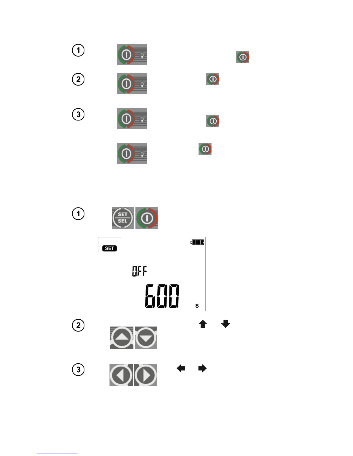
Turn on the meter with button.
Short press button to turn the
screen backlight on; press the button
again to turn the backlight off.
Switch on the meter by pressing and
and holding button for approx. 2
sec.
Emer-
gency si-
tuations.
Pressing button for approx. 7 sec-
onds will turn off the meter in case of
emergency.
3 Meter Configuration
Turn on the meter by pressing and
keeping SETUP button pressed.
Use buttons and to set Auto-OFF
time or to inactivate this function (horizon-
tal lines –Auto-OFF function is inactive).
Auto-OFF function is used to turn-off inac-
tive meter after a preselected time.
Use and buttons to enter the
screen with audio message settings:
bEEP.

OPERATING MANUAL MIC-2501 version 1.04
7
Use and buttons to turn the audio
messages ON ( ) or OFF ( ).
Press and buttons to enter the set-
ting the type of absorption coefficients:
FAC.
Use and buttons to set Ab1, Ab2 (
) parameters or PI, DAR ( ).
Use and buttons to enter the
screen with software update: UPdt.
OPERATING MANUAL MIC-2501 version 1.04
8
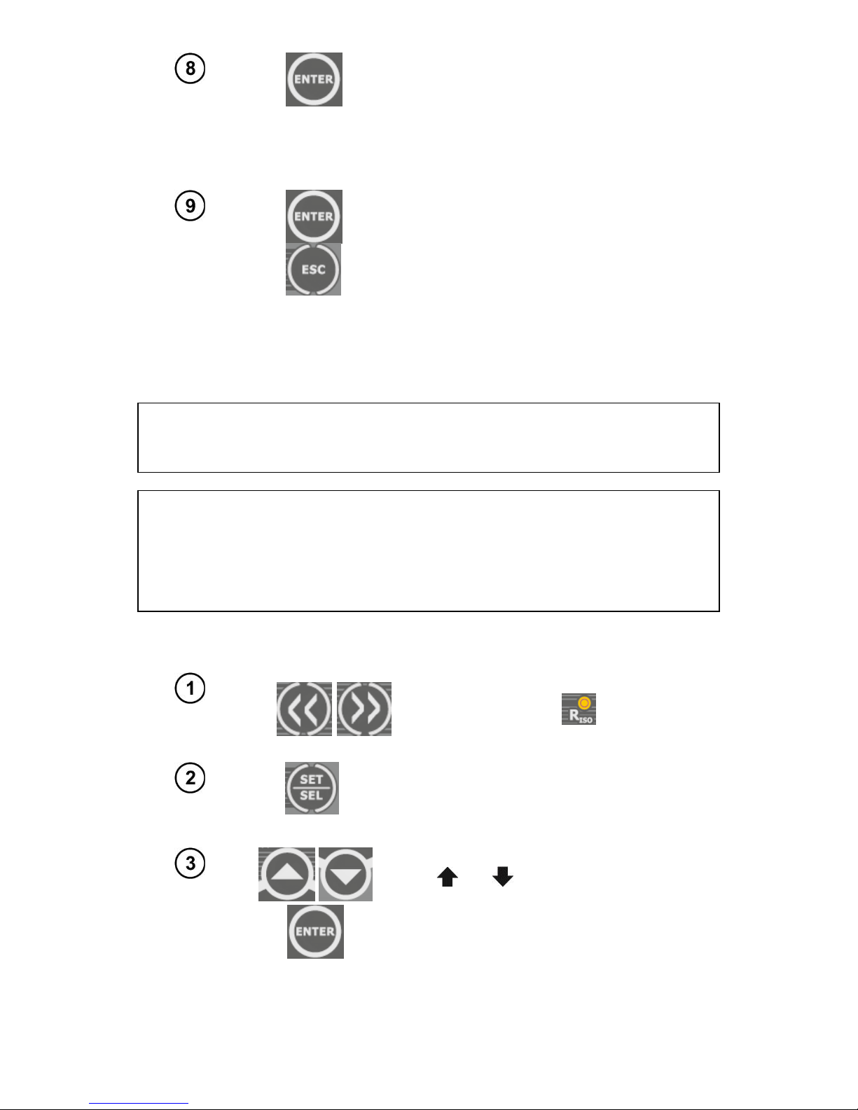
Press ENTER to enter the update mode. The
update process is described in Chapter 7
After changing the parameters, you may exit SETUP menu (not applicable for Up-
date screen):
Press ENTER to memorize settings
or use ESC button to go to the measurement
screen without approving the changes.
4 Measurements
4.1 Measurement of insulation resistance
WARNING:
The tested object must not be live.
Attention:
During measurement, especially of high resistances, make sure that test leads
do not touch each other and probes (crocodile clips), because such a contact
may cause the flow of surface currents resulting in additional error in measure-
ment results.
4.1.1 Double-lead measurement
Use << or >> button to start the meas-
urement of RISO (LED is on). The
meter is in voltage measurement mode.
Press SET/SEL button to select the measure-
ment voltage UISO, time used for calculating the
absorption coefficients t1, t2, t3 and the inter-
val between the parameter points ChA.
Use and buttons to set UISO value
and confirm it by pressing ENTER
or

OPERATING MANUAL MIC-2501 version 1.04
9
use button to enter the setting of
times for calculating the absorption coeffi-
cients.
Use and buttons to set t1 value,
use button to start setting t2 and then
t3 value. Press again to enter the set-
ting of time interval ChA of recording
RISO.
Defining ChA interval will enable the user, using Sonel Reader software, to plot the resistance chart
and current chart using the data obtained from the performed measurement (see example below).
Use and buttons to set the inter-
val (15, 30, 45 or 60 sec.). Horizontal
lines indicate unavailability of recording
characteristics.

OPERATING MANUAL MIC-2501 version 1.04
10
or
Press ENTER to confirm settings or
press ESC to exit without saving the
changes.
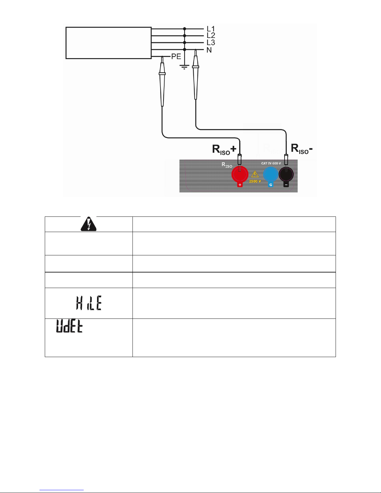
Connect test leads according to the drawing.
The meter is ready
for measurement.
Press and hold START push-button.
The measurement is performed continu-
ously until you release the button or the
pre-set time is reached.
for 5 sec.
or
+
In order to maintain (hold) the measure-
ment, press and hold START button for 5
sec. or press ENTER while holding
START button pressed - symbol
will be displayed indicating
automatic measurement, now the buttons
may be released. The measurement will
end after the longest pre-set time (t1, t2
or t3) runs out. To interrupt or terminate
the measurement earlier in the absence

OPERATING MANUAL MIC-2501 version 1.04
11
of pre-set t1, t2 or t3 values (measure-
ment without time limit), press again
START or ESC button.
View of the screen during
measurement.
means that the measure-
ment was started with
ENTER button or by press-
ing and holding START but-
ton for approx. 5 sec.
Use SET/SEL to go to display leakage cur-
rent IL.
After the measurement is
completed or stopped,
read the result. The re-
sults of all completed
measurements will be dis-
played (even when the
measurement was inter-
rupted/stopped e.g. after
60 seconds). When the
meter switched into
standby mode, the meas-
urement result may be re-
called by pressing
ENTER.

OPERATING MANUAL MIC-2501 version 1.04
12
Use and to see individual components of the
result in the following order:
RISO→IL→Ab2→Ab1→Rt3→It3→Rt2→It2→Rt1→It1
→RISO.
If the measurement is stopped, the displayed val-
ues will present the results of partial measurements
that have been completed and "---" will represent
uncompleted partial measurements.
If the characteristic was measured, then the meas-
urement results may be read between It1 and RISO.
Note:
During measurements of insulation resistance, dangerous voltage of approx.
2.5kV occurs at the ends of measurement wires of MIC-2501 meter.
It is forbidden to disconnect test leads before the measurement is completed.
Failure to obey the above instruction will lead to high voltage electric shock and
make it impossible to discharge the tested object.
- Disabling t2 will also disable t3.
- Timer measuring the measurement time is started when UISO voltage is stabilized.
- Symbol LIMIT means operation with limited inverter power. If this condition persists for 20 seconds,
the measurement is interrupted.
- If the timer reaches characteristic points (tx times or characteristic times), then for 1s instead UISO a
symbol (mnemonic) of this point is displayed which is accompanied by a long beep.
- If any of the measured values of partial resistance is out of range, the value of the absorption coefficient
is not displayed –the display shows dashes.
- During the measurement LED is flashing in yellow.
- When the measurement is complete, capacity of the tested object is discharged by shorting terminals
RISO+and RISO-with resistance of approx. 100 k. Message „diS”is displayed. Do not disconnect the
test leads before the object capacity id discharged.
- When during viewing the results, voltage is present at terminals RISO, LED RISO will blink in red and
additional two-tone beep will be generated.
- In case of power cables measure the insulation resistance between each conductor and other conduc-
tors shorted and grounded (figure below).
OPERATING MANUAL MIC-2501 version 1.04
13
Additional information displayed by the meter
Test voltage is present on terminals of the meter.
NOISE!
Interference voltage higher than 25V but lower than 50V, is present
on the tested object. Measurement is possible but may be bur-
dened with additional uncertainty.
READY disappears, LED
lights red, two-tone beep
Interference voltage higher than 50 V, is present on the tested ob-
ject. The measurement is blocked.
LIMIT I!
Activation of current limit. The symbol displayed is accompanied by
a continuous beep.
Breakdown of the tested object insulation, the measurement is in-
terrupted. The message appears after displaying LIMIT I! for 20 s
during the measurement, when the voltage previously reached the
nominal value.
, RISO LED is
blinking in red and two-
tone acoustic signal is
generated
During the measurement, AC voltage appeared or the object can-
not be discharged for 30 seconds. Immediately disconnect the test
leads.
4.1.2 Three-lead measurement
In order to eliminatethe influence of surface resistance intransformers, cables, etc. the three-
lead measurement is used. For example:
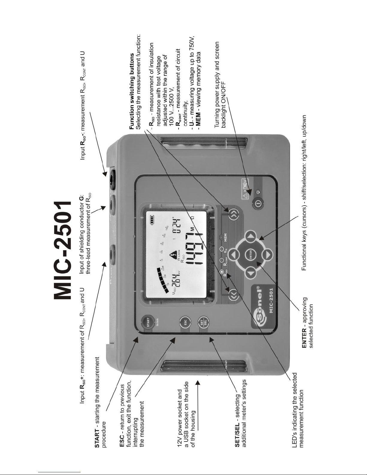
at the measurement of inter-winding resistance of a transformer, Gsocket of the meter should be
connected to the transformer tank;

OPERATING MANUAL MIC-2501 version 1.04
14
when measuring insulation resistance between one of the cable conductors and the cable jacket,
the effect of surface resistances (important in difficult weather conditions) is eliminated by con-
necting a piece of metal foil insulating the tested conductor with Gsocket of the meter;
The same shall apply when measuring the resistance between two conductors of the cable, at-
taching to Gterminal other conductors that do not take part in the measurement.
Cable sheath
Metal foil wrapped around the conductor insulation
Conductor

OPERATING MANUAL MIC-2501 version 1.04
15
4.2 Low-voltage measurement of resistance
4.2.1 Measurement of resistance of protective conductors and equipotential
bonding with 200 mA current
Use << or >> button to start the measurement of RCONT
(LED is on). The meter is in the voltage measure-
ment mode.
The meter is ready for meas-
urement.
Connect the meter to the tested object.
Trigger the measurement by pressing the START button.
Read out the result.
Press START push-button in order to start next measure-
ment without disconnecting test leads from the object.
OPERATING MANUAL MIC-2501 version 1.04
16
Additional information displayed by the meter
NOISE!
Interference voltage occurs on the tested object. The
measurement is possible however it will be burdened
with additional uncertainty that is specified in the tech-
nical data.
, LED
RCONT is blinking
in red and two-
tone acoustic sig-
nal is generated
Interference voltage exceeds the allowable value, the
measurement is blocked.
4.2.2 Compensation of test leads resistance
In order to eliminate the impact of the resistance of test leads on measurement result RCONT, the
compensation (auto-zeroing) of resistance may be performed.
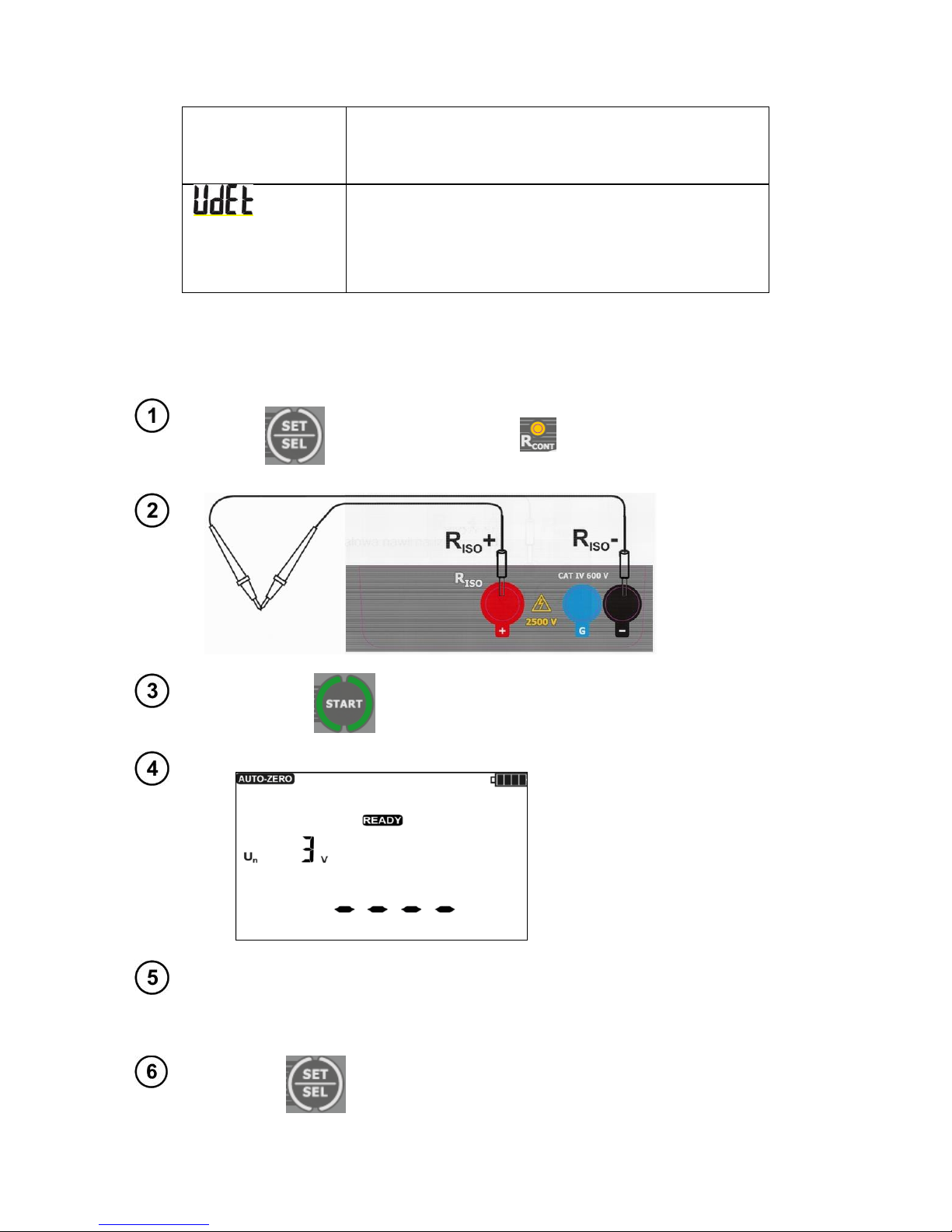
In RCONT mode (LED is on) use SET/SEL button to en-
ter the screen with Autozeroing the test leads.
Short the test
leads –message
READY will be
displayed.
Press START.
AUTO-ZERO message starts to
blink, which confirms completion
of test leads calibration.
The result is a compensated
value and correction is available
for RCONT. The compensation is
active even after the meter is
switched off and on again.
In order to remove the compensation of the leads resistance (return to default cal-
ibration), perform the above-mentioned activities with test leads open, instead of
test results, the display will show message oFF (compensation of test leads is
turned off).
Return to RCONT measurement screen by pressing
SET/SEL

OPERATING MANUAL MIC-2501 version 1.04
17
4.3 Voltage measurement
Use << or >> button to start the meas-
urement of (LED is on). The
meter is in the voltage measurement
mode.
Connect the meter to a
voltage source.
Measurement is per-
formed in a continu-
ous manner.
Additional information displayed by the meter
>750V, LED is
blinking in red,
two-tone acoustic
signal is generated
Measuring range is exceeded. Voltage is higher than
acceptable. Immediately disconnect the test leads.
~
-
When AC voltage is detected, the device will display
symbol "~"("wave") and when DC voltage is detected,
the device will display symbol "-" for negative polarity
or "nil" for positive polarity.

OPERATING MANUAL MIC-2501 version 1.04
18
5 Memory of measurement results
MIC-2501 meters have memory divided into 10 banks of 99 cells. Thanks to dynamic memory allo-
cation, each of the memory cells can contain different quantity of single measurement results, depending
on the needs. Optimal use of the memory can be ensured in this way. Each measurement result can be
stored in a memory cell marked with a selected number and in a selected memory bank. Thanks to this,
the user of the meter can, at his/her option, assign memory cell numbers to individual measurement
points and the memory bank numbers to individual facilities. The user may also perform measurements
in any chosen sequence and repeat them without losing other data.
Memory of measurement results is not deleted when the meter is switched off. Thanks to this, the
data can be later read or sent to a computer. The number of a current memory cell or memory bank is
not changed either.
Note:
- Results of measurements performed for all measuring functions can be stored in one memory cell,
excluding U .
- After entering the measurement result, the ID number of the cell is automatically increased.
- It is recommended to delete the memory after reading the data or before performing a new series of
measurements that may be stored into the same memory cells as the previous ones.
5.1 Storing the measurement results in the memory
After completing measurement
press ENTER.
The cell is empty.
The cell is partially
occupied by the same
type of result, which
is to be entered.
Table of contents
Other Sonel Measuring Instrument manuals

Sonel
Sonel MIC-10k1 User manual

Sonel
Sonel MIC-5 User manual

Sonel
Sonel MIC-2 User manual

Sonel
Sonel CMP-1015-PV User manual

Sonel
Sonel CMP-200 User manual

Sonel
Sonel MIC-15k1 User manual

Sonel
Sonel MZC-20E User manual

Sonel
Sonel MRU-11 User manual

Sonel
Sonel MMR-650 User manual

Sonel
Sonel DIT-120 User manual


Popular Measuring Instrument manuals by other brands

Bosch
Bosch GLM 20 Original instructions

M & I Instruments
M & I Instruments DT-86 instruction manual

Zenner
Zenner zelsius C5-ISF Installation and operating instructions

LaserLiner
LaserLiner LaserRange-Master Gi7 Pro operating instructions

DKS
DKS AQUATRACE-IV manual

Flexim
Flexim FLUXUS WD Operating instruction


