Sonel KT-800M User manual

USER MANUAL
FEVER WARNING SYSTEM
KT-800M


USER MANUAL
FEVER WARNING SYSTEM
KT-800M
SONEL S.A.
Wokulskiego 11
58-100 Świdnica
Poland
Version 1.00 26.08.2020

KT-800M –USER MANUAL
2
KT-800M Fever Warning System complies with current EU directives related to electromagnetic
compatibility and safety.
All products of Sonel S.A. are manufactured in accordance with Quality Management System which
is approved to ISO9001:2008 for the design, manufacturing and servicing.
Due the continuous development of our products, we reserve the right to introduce changes and im-
provements in the thermal imaging camera and in the software described in this manual without prior
notice.
Copyrights
©Sonel S.A. 2020. All rights reserved. This manual may not be copied, reproduced, translated or
transferred to any electronic carriers or in machine-readable form, in whole or in part, without the prior
written consent of Sonel S.A.

KT-800M –USER MANUAL
3
CONTENTS
1Safety ................................................................................................................4
2Description of the system...............................................................................5
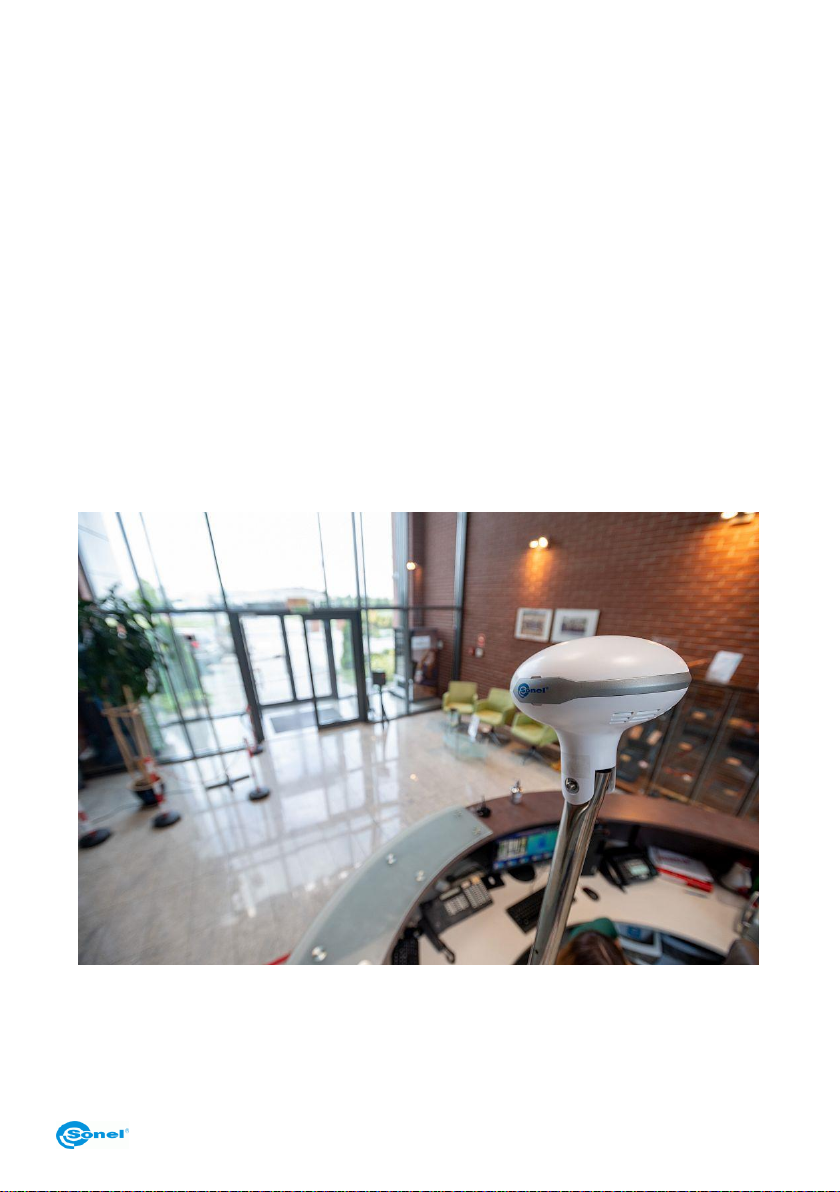
2.1 Product application site............................................................................................ 5
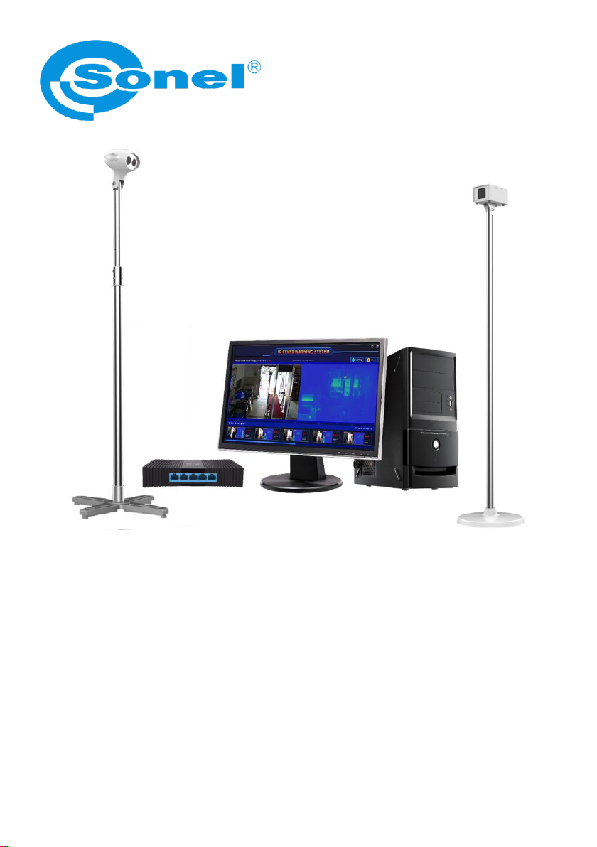
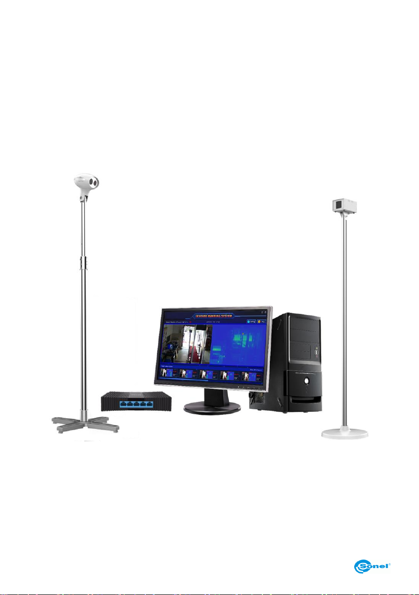
2.2 Product configuration...............................................................................................6
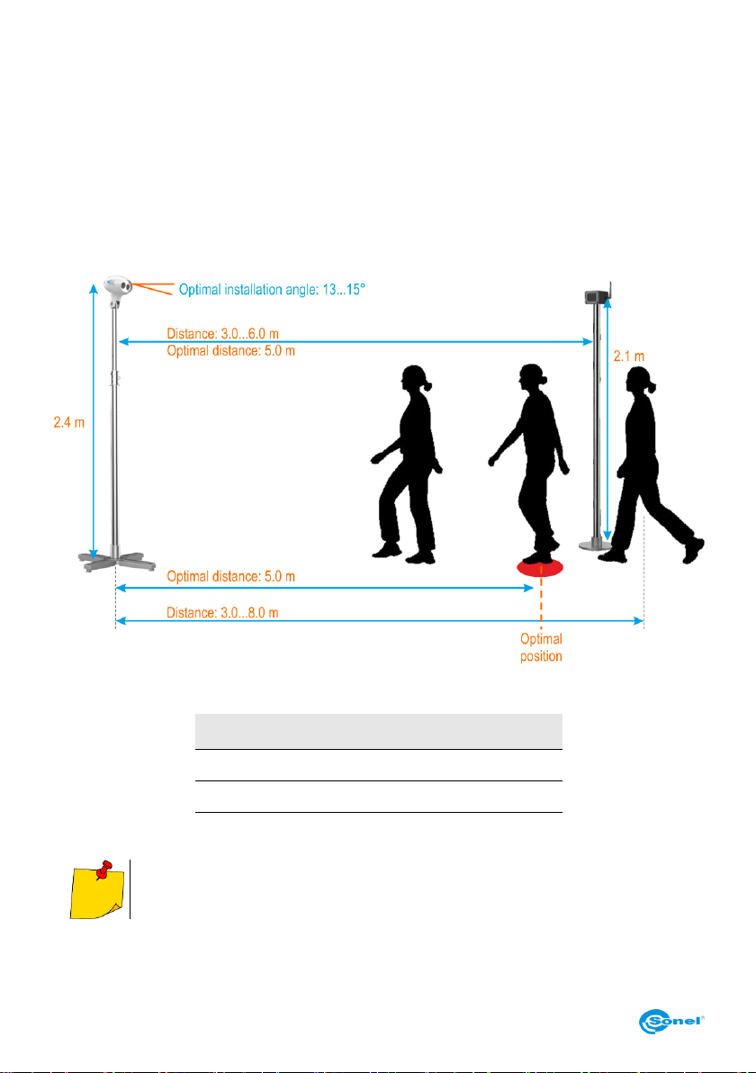
2.3 Deployment requirements........................................................................................7
3Installation........................................................................................................9
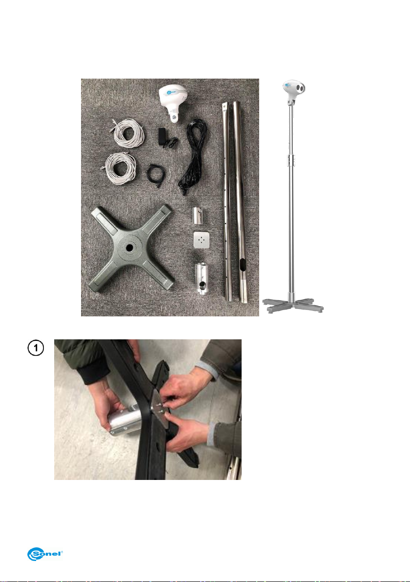
3.1 Camera installation .................................................................................................. 9
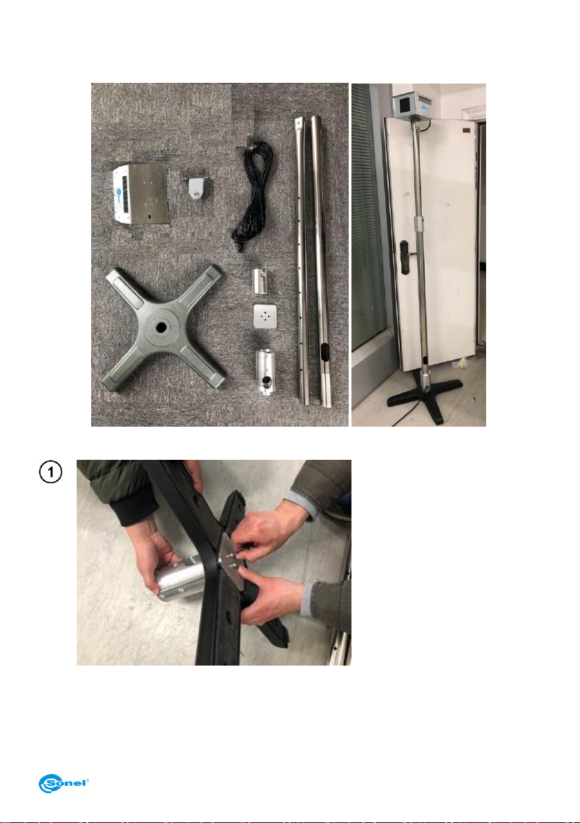
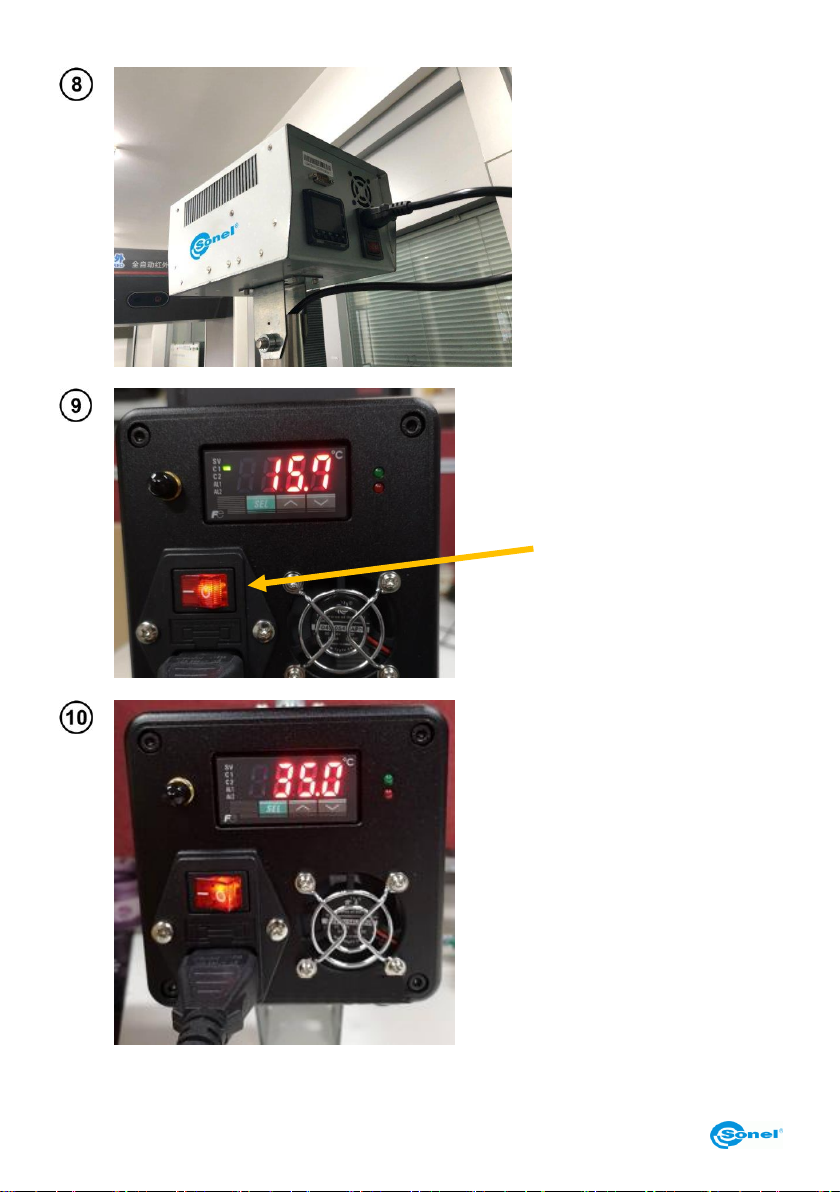
3.2 Blackbody installation ............................................................................................ 13
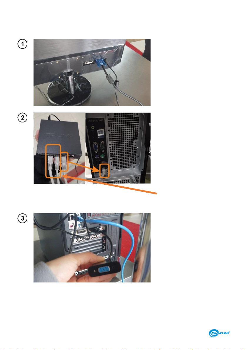
3.3 Assemble the computer and connect to power...................................................... 18
4Function introduction....................................................................................20
4.1 Real-time preview .................................................................................................. 20
4.2 History and processing .......................................................................................... 21
4.3 NVR monitoring...................................................................................................... 21
4.4 Settings..................................................................................................................21
4.5 Help........................................................................................................................22
4.6 Over temperature alarm screenshot display area.................................................. 22
5History record ................................................................................................23
5.1 History record operation.........................................................................................23
5.2 Single group history record....................................................................................26
6Function setting.............................................................................................27
6.1 Device management.............................................................................................. 28
6.2 System setting ....................................................................................................... 29
6.2.1 Alarm parameter setting.................................................................................................29
6.2.2 Settings of shielding area...............................................................................................30
6.2.3 Black body area setting .................................................................................................31
6.2.4 Image registration..........................................................................................................33
6.2.5 Image debugging...........................................................................................................34
6.2.6 Other settings................................................................................................................35
7Specifications.................................................................................................36
8Cleaning and maintenance ...........................................................................37
9Storing ............................................................................................................37
10 Dismantling and disposal .............................................................................37
11 Standard accessories....................................................................................38
12 Manufacturer ..................................................................................................38

KT-800M –USER MANUAL
4
1 Safety
The purpose of this content is to ensure that the user uses the product correctly to avoid danger or
property damage. Before using this product, please read this instruction carefully and keep it for fu-
ture reference.
Ignoring warnings shown below may cause death or serious injury:
In the installation and use of this product, it is necessary to strictly abide by the various national
and regional electrical safety regulations.
Do not connect multiple devices to the same power adapter (exceeding the load of the adapter
may cause excessive heat or cause a fire).
Disconnect the equipment from the power supply during wiring, disassembly, etc.
If the device emits smoke during use, produces a foul odor, or emits noise, immediately turn off
the power and contact the distributor or manufacturer to deal with related matters.
If the device does not work properly, contact the distributor or manufacturer. Do not disassemble
or modify the device in any way.
Ignoring the precautions shown below can cause injury or property damage:
Do not drop objects on the device or shake the device vigorously. Keep the device away from lo-
cations subject to magnetic interference. Avoid installing the device in a place subject to vibration
or impact. Ignoring this may damage the device.
In order to ensure the accuracy of human body temperature screening, do not use the device in
the environment temperature above 35℃or below 15℃, as well as high humidity (more than
85%). Try to avoid the lights in the scene and the passengers Interference from high-temperature
targets.
Do not forcefully pull the cable, which will cause the internal cable connection to break or fall off.
Do not aim the device at strong light objects, such as the sun, electric iron, etc., otherwise the
device will be damaged.
Do not place the device in direct sunlight, poorly ventilated locations, or near heat sources such
as heaters or heaters. Ignoring this may cause a fire hazard.
Do not turn the machine on and off frequently. The restart interval after shutdown is not less than
30 seconds.

KT-800M –USER MANUAL
5
2 Description of the system
The full-automatic infrared thermal imaging temperature measurement alarm system can perform
large-area monitoring in crowded public places. The system's non-contact preliminary screening of
body temperature can quickly find and track over-temperature personnel to help troubleshoot human
fever.
This system combines advanced technology such as infrared human body temperature measurement
algorithm and AI intelligent face recognition. The temperature measurement is accurate and the op-
eration is simple and convenient. Multi-target tracking can ensure that no targets are missed. Custom
alarm temperature zones and high-temperature shielding settings can avoid interference from other
high-temperature objects. People who find over-temperatures can automatically alarm and take pic-
tures for storage. It is convenient for users to query and classify management. Ideal equipment for
health and epidemic prevention in public places.
2.1 Product application site
The automatic infrared thermal imaging temperature measurement and alarm system can be applied
to crowded public places such as government agencies, airports, stations, large factories, schools,
and commercial centers. It is mainly installed and deployed at the entrances, passages, lobby, etc.
Application scenario is shown in Figure 1-1.
Small application scenario

KT-800M –USER MANUAL
6
2.2 Product configuration
IR Fever Warning System with Integrated delivery could be open to use on site. The main product
configuration is shown below. Network hard disk recorder as an optional if video recording is required.
Standard set:
Camera head + stand,
Black body + stand,
Switch,
PC kit.

KT-800M –USER MANUAL
7
2.3 Deployment requirements
The KT-800M automatic infrared thermal imaging temperature measurement alarm system belongs
to precision temperature measurement and imaging equipment, which has certain requirements for
deployment applications. The precautions are as follows:
Installation Environment
oThe device should be placed indoors and the ambient temperature should be kept relatively
constant. If the actual application scene is outdoors, it’s necessary to setup a tent or shelter,
such as good sealing environment and keep the environment stable.
oThe position of the device head needs to be well-lit (illumination ≥100 Lux), and it should be
avoided in the position of backlight.
oThere should be no air-conditioning outlets within 3 meters of the location of the equipment
head.
oThe field of view monitored by the device head must not be disturbed by strong external heat
sources such as light and sun.
Head layout
oReasonably arrange the position of the KT-800M head, and the downward plan angle is 13° -15°.
oReasonably arrange the detection position and range of personnel. The position of KT-800M
camera from the forehead of the person under test is 3.0-8.0 meters, and the best test posi-
tion is 5.0 meters.
Black body layout
oReasonably arrange the position of the KT-800M black body, and generally place the black body
horizontally (require that the front of the black body can be all and face the image display).
oReasonably arrange the position of the black body. The position of the KT-800M black body
from the head is 3.0-6.0 meters, and the optimal setting position is 5.0 meters.

KT-800M –USER MANUAL
8
Tested person requirements:
oAfter outdoor sun exposure or after strenuous exercise, test in an indoor environment for
5 minutes after peaceful adjustment;
oPeople enter indoors from outdoor scenes. It is recommended to walk through the corridor
buffer for at least 10 seconds before stepping into the detection position. If the temperature
difference between indoor and outdoor is large, it is recommended to stay indoors for
2-3 minutes before testing;
oMake sure that the entire face of the person under test is in the field of vision of the device,
and that the face and forehead cannot be blocked (hats, scarves, sunglasses, masks, antipy-
retic stickers and other objects that may block the face. It is recommended to remove them in
advance and adapt for 0.5-1 minutes carry out testing.
Product deployment
Distance (m)
Horizontal observation
range (m)
3
2.02
5
3.36
8
5.38
If the installation of the camera is restricted by the site, the installation height can be
adjusted appropriately. It is recommended that the installation height of the camera is
not lower than 2.0 m, and the height of the black body is not lower than 1.8 m.

KT-800M –USER MANUAL
9
3 Installation
3.1 Camera installation
Install the base.
Assemble chassis + chassis
adapter + counterweight.
Fasten with 4 M6x25 screws.

KT-800M –USER MANUAL
10
Install the pole and chassis
adapter.
Fasten it with 8 M4x10 screws.
Install the middle connecting
sleeve of the telescopic rod.
Install the screws shown. Do
not fasten first!
Pass 2 long network cables
and 1 power cable through the
bottom of the support rod, and
then from the movable rod of
the telescopic rod.

KT-800M –USER MANUAL
11
Fix the second section of the
telescopic rod on the interme-
diate adapter.
Use the positioning screws on
the adapter to position the up-
per telescopic rod in the sixth
hole.
Tighten the screws installed in
step .
Insert the 2 network cables
and 1 power cable from the top
of the support rod into the card
slot interface of the device’s
head.
Fasten the device’s head and
the vertical rod.
Fasten it with M10x60 screws
(the head and the support rod
have gaskets).

KT-800M –USER MANUAL
12
Adjust the depression angle by
about 15 degrees.

KT-800M –USER MANUAL
13
3.2 Blackbody installation
Install the base.
Assemble chassis + chassis
adapter + counterweight.
Fasten it with 4 M6x25 screws

KT-800M –USER MANUAL
14
Install the pole and chassis
adapter.
Fasten it with 8 M4x10 screws.
Install the middle connecting
sleeve of the telescopic rod.
Install the screws shown. Do
not fasten first!
Pass the power cord through
the bottom of the support rod
and out from the movable rod of
the telescopic rod.

KT-800M –USER MANUAL
15
Fix the second section of the
telescopic rod on the intermedi-
ate adapter.
Use the positioning screws on
the adapter to position the up-
per telescopic rod in the fourth
hole.
Tighten the screws installed in
step .
Install the black body head and
adapter.
Fasten it with 4 M4x6 screws.
Fasten the black body head and
the vertical rod.
Fasten it with M10x50 screws.

KT-800M –USER MANUAL
16
Plug in the black body power
connector and turn on the
switch.
Turn on the power of the black
body and turn on the power
switch. The black body displays
the temperature as the current
ambient temperature and will
keep increasing.
Power switch
Click the up and down keys
next to the setting key to set the
black body temperature to 35
degrees.
Click the setting key again to
save the setting.

KT-800M –USER MANUAL
17
Click the setting button as
shown in the figure - the factory
setting temperature will be dis-
played on the black body.
Setting button
Wait about 15 minutes, the
temperature of the black body
is over, the temperature is sta-
ble at the set temperature, and
all the indicators in the indicator
area are off.

KT-800M –USER MANUAL
18
3.3 Assemble the computer and connect to power
Assemble the display, connect
the VGA cable and the DC
power supply cable.
Note: The display power adapt-
er cannot be mixed with the
power adapter of the camera
Two long network cables on the
camera are connected to the
switch, and the switch is con-
nected to the network port of
the host box with a short net-
work cable.
Note: The power adapter of the
switch cannot be mixed with
other adapters, otherwise there
is a risk of burning the switch
Two long network cables of the
camera
The computer's independent
graphics card interface is con-
nected to the VGA cable via the
adapter cable, and the comput-
er's host is connected to the
speaker.
Table of contents
Other Sonel Measuring Instrument manuals

Sonel
Sonel MIC-2510 User manual

Sonel
Sonel MRU-30 User manual

Sonel
Sonel MPI-540 User manual

Sonel
Sonel MPI-525 User manual

Sonel
Sonel MRU-200-GPS User manual

Sonel
Sonel CMP-1015-PV User manual

Sonel
Sonel MRU-30 User manual

Sonel
Sonel PAT-810 Installation manual

Sonel
Sonel DIT-130 User manual

Sonel
Sonel MZC-305 User manual