Sonel MMR-620 User manual

LOW-RESISTANCE METER
MMR-620
OPERATING MANUAL
Revision 1.6

OPERATING MANUAL MMR-620 Revision 1.62
We appreciate your having purchased our low-resistance meter. The MMR-620 meter is a modern,
high-quality measuring device, which is easy and safe to use. Please acquaint yourself with the pre-
sent manual in order to avoid measuring errors and prevent possible problems related to operation of
the meter.

OPERATING MANUAL MMR-620 Revision 1.6 3
TABLE OF CONTENTS
1 SAFETY ....................................................................................................................5
2 MENU........................................................................................................................6
2.1 LCD CONTRAST .....................................................................................................7
2.2 TRANSMISSION OF DATA (RS-232)..........................................................................7
2.2.1 Computer connection accessories .................................................................7
2.2.2 Connection of the meter to a computer..........................................................7
2.3 MEASUREMENT MODE............................................................................................7
2.4 DISPLAY SETTINGS..................................................................................................7
2.5 RESULT DISPLAY CONFIGURATION ..........................................................................8
2.6 DEFAULT SETTINGS..............................................................................................10
2.7 SELECTION OF THE LANGUAGE.............................................................................11
2.8 ADVANCED FUNCTIONS ........................................................................................11
2.8.1 Manual calibration......................................................................................11
2.8.2 Auto-calibration...........................................................................................12
2.8.3 Return to the default calibration..................................................................12
2.8.4 Programme upgrade....................................................................................12
2.9 INFORMATION ON THE MANUFACTURER AND THE PROGRAMME..............................13
3 MEASUREMENTS................................................................................................14
3.1 CONFIGURATION OF THE MEASUREMENT OPTIONS ................................................14
3.1.1 Selection of the type of object......................................................................14
3.1.2 Flow of current............................................................................................15
3.1.3 Measurement triggering ..............................................................................15
3.1.4 Saving to memory........................................................................................16
3.1.5 Measurement range selection......................................................................16
3.2 CONNECTION OF THE METER AND START OF MEASUREMENTS.................................17
4 MEMORY OF THE MEASUREMENT RESULTS ...........................................22
4.1 MANUAL SAVING OF MEASUREMENT RESULTS IN THE MEMORY...............................22
4.2 AUTOMATIC SAVING OF MEASUREMENT RESULTS IN THE MEMORY..........................23
4.3 MEMORY BROWSING.............................................................................................24
4.4 MEMORY ERASING................................................................................................24
5 POWER SUPPLY ..................................................................................................26
5.1 MONITORING OF THE POWER SUPPLY VOLTAGE.....................................................26
5.2 REPLACEMENT OF ACCUMULATORS ......................................................................26
5.3 CHARGING OF ACCUMULATORS ............................................................................27
5.4 GENERAL PRINCIPLES REGARDING USING NI-MH ACCUMULATORS........................29
6 CLEANING AND MAINTENANCE....................................................................31

OPERATING MANUAL MMR-620 Revision 1.64
7 STORAGE ..............................................................................................................31
8 DISMANTLING AND UTILIZATION................................................................31
9 ATTACHMENTS...................................................................................................32
9.1 TECHNICAL DATA.................................................................................................32
9.2 STANDARD ACCESSORIES......................................................................................33
9.3 ADDITIONAL ACCESSORIES ...................................................................................33
9.4 MANUFACTURER..................................................................................................34
10 LABORATORY SERVICE ...................................................................................35

OPERATING MANUAL MMR-620 Revision 1.6 5
1 Safety
The MMR-620 meter has been designed to realise measurements of resistance of dif-
ferent kinds of connections (welded, soldered, contact connections) in electric installations.
The results of the measurements determine the safety conditions of the installation. There-
fore, in order to provide conditions for correct operation and the correctness of the obtained
results, the following recommendations must be observed:
•Before you proceed to operate the meter, acquaint yourself thoroughly with the present
manual and observe the safety regulations and specifications determined by the pro-
ducer.
•The MMR-620 meter has been designed for the purpose of low-resistance measure-
ments. Any other application than those specified in the present manual may result in a
damage to the device and constitute a source of danger for the user.
•In case of measurements of installations, sub-assemblies and devices under a danger-
ous voltage, the MMR-620 meters may solely be operated by qualified personnel who
are properly authorised to work on electric installations. Operation of the meter realised
by unauthorised personnel may result in damage to the device and constitute a source
of danger for the user.
•The device cannot be used in the grid and with other devices in special interiors, for
example those of a dangerous atmosphere regarding the risk of explosion or fire.
•It is unacceptable to operate the following:
•A damaged meter which is completely or partially out of order,
•A meter with damaged cable insulation,
⇒A meter stored for an excessive period of time in disadvantageous conditions (e.g.
excessive humidity). If the meter has been transferred from a cool to a warm
environment of a high level of relative humidity, do not realise measurements
until the meter has been warmed up to the ambient temperature (approxi-
mately 30 minutes).
⇒Before measurements may commence, make sure the cables are connected to the
appropriate measurement sockets.
⇒Do not operate a meter with an open or incorrectly closed battery (accumulator)
compartment or power it from other sources than those specified in the present
manual.
⇒The meter’s inputs are electronically protected from power surge, as a result for
example, of accidental connection to the power supply source:
- for all input combinations – up to 440VAC for 10 seconds.
•Repairs may be realised solely by an authorised service point.
•The device complies with the following norm; PN-EN 61010-1
Note:
The manufacturer reserves the right to modify the appearance, accessories and
technical data of the meter.

OPERATING MANUAL MMR-620 Revision 1.66
Menu
2 Menu
The menu is available at any position of the knob but MEM.

OPERATING MANUAL MMR-620 Revision 1.6 7
2.1 LCD contrast
Using the buttons and set the contrast value and press to confirm the setting.
2.2 Transmission of data (RS-232)
2.2.1 Computer connection accessories
What is necessary in order to operate the meter with a computer is a RS-232 cable and
appropriate software. If the required accessories such have not been purchased along with
the meter, then they are available from the manufacturer or an authorised distributor.
The accessories may be used in case of many devices manufactured by SONEL S.A.
which are equipped with the RS-232 interface.
Detailed information regarding software is available from the manufacturer or an
authorised distributor.
2.2.2 Connection of the meter to a computer
1. Connect the cable to the serial port (RS-232) of the computer and to the RS-232 socket
of the meter.
2. Activate the data transmission mode in the MENU.
3. Start the appropriate programme in the computer and follow the instructions.
2.3 Measurement mode
The MENU-Measurement mode option is described in Chapter 3.1
2.4 Display settings
The MMR-620 meter permits selection of two modes of presentation of measurement re-
sults:
Menu
LCD
contrast
Trans-
mission
of data
Meas-
urement
mode
Display
settings

OPERATING MANUAL MMR-620 Revision 1.68
Menu
Display
settings
Result
display
configu-
ration
2.5 Result display configuration
This option permits to establish the upper and lower limits, between which the average
result of measurement must be contained. Results beyond this range will be signalled by
two long sound signals and the symbol R>Rmax or R<Rmin displayed instead of the result.
In the mode of manual saving of the result in the memory, the limits are displayed in place
of the bank and cell number. In the mode of automatic saving of the result in the memory,
it is possible to view for three seconds the set limits pressing the ESC button.
The limits of the acceptable range of the measurement results is set in MENU:

OPERATING MANUAL MMR-620 Revision 1.6 9
Menu
Result
display
configu-
ration

OPERATING MANUAL MMR-620 Revision 1.610
Menu
Result
display
configu-
ration
Default
settings
Note:
- Should the option NO be selected and the button pressed, the previous settings will
be re-established.
2.6 Default settings
The default settings are the following:
•Type of the object – resistance object,
•selection of the measurement range – automatic,
•flow of current – bidirectional,
•trigering mode – normal,
•memory entry – manual,
•limits in the window mode: upper limit – 199,9Ω, lower limit – 0 Ω,
•window mode off,
•result display – all results.

OPERATING MANUAL MMR-620 Revision 1.6 11
2.7 Selection of the language
2.8 Advanced functions
2.8.1 Manual calibration
The user may perform manual calibration of the meter, provided they have standard
resistors, minimum grade 0.05%, of the following nominal values: 0,2mΩ, 2mΩ, 20mΩ,
200mΩ, 2Ω, 20Ω, 200Ωand 2kΩ. Calibration is performed separately for each range.
Menu
Selection
of the
language
Advanced
functions
Manual
calibration

OPERATING MANUAL MMR-620 Revision 1.612
Menu
Manual
calibra-
tion
Auto-
calibra-
tion
Return to
default
calibra-
tion
Pro-
gramme
upgrade
Note:
The guarantee does not include faulty operation of the device which is caused by er-
roneous application of this function.
2.8.2 Auto-calibration
The user may perform manual auto-calibration of the meter offset. Auto-calibration is
realised separately for each range.
Once Auto-calibration has been selected in the MENU follow the information dis-
played in the screen, as in the case of manual calibration.
Notes:
- To perform auto-calibration use the measurement leads applied for the purpose of
measurements: connect the U1and U2leads as well as I1and I2.
The guarantee does not include faulty operation of the device which is caused by er-
roneous application of this function.
2.8.3 Return to the default calibration
In order to return to the default calibration, enter this option in the MENU and select
YES and confirm pressing .
This option erases the results of manual calibration and auto-calibration realised by
the user. The factors calculated in the calibration process realised by the manufacturer
are re-established.
2.8.4 Programme upgrade
It is possible to upgrade the control programme without having the meter serviced.
Should upgrading be necessary, the following actions will be realised:
•Download the meter programming software from the manufacturer’s web site
(www.sonel.pl),
•Connect the meter to a computer,
•In the MENU enter the option Advanced and then Programme upgrade and con-
firm the displayed information has been read,
•Install and start the meter programming software in the computer,
•In the programme select the port, activate the „Test connections” function, and then
start the Programming function,
•Proceed ion accordance with the instructions displayed by the programme.

OPERATING MANUAL MMR-620 Revision 1.6 13
Notes:
The function is designed to be used solely by those users who are familiar with
computer equipment.
The guarantee does not cover faults caused by incorrect application of this
function.
Before you proceed to programming, charge the accumulators.
During programming do not turn the meter off or disconnect the transmission
cable.
- During programming the only active button is .
- In the case of this function the meter does not turn off automatically.
2.9 Information on the manufacturer and the programme
In order to obtain basic information on the manufacturer of the meter and the version of
the programme, perform the following actions:
•in MENU select About producer & programme,
•press the button .
Menu
Ad-
vanced
functions
Pro-
gramme
upgrade
Informa-
tion on
the
manufac-
turer and
pro-
gramme

OPERATING MANUAL MMR-620 Revision 1.614
Meas-
ure-
ments
Meas-
urement
options
Type of
the ob-
ject
3 Measurements
3.1 Configuration of the measurement options
Before you proceed to measurements, adjust the parameters of the measurement
process to the properties of the measured object. This is done by selection of the appropri-
ate options in MENU – Measurement mode.
3.1.1 Selection of the type of object
The MMR-620 meter permits selection of one of the three types of objects:
The measurement marked with the symbol is the shortest measurement (3s) and
its purpose is to test objects of purely resistance-related character.
The symbol means the measurement mode for inductive objects. This
mode is based upon special object charging procedures, which are indispensable to per-
form correct measurements of resistance of highly inductive objects. In this mode the dura-
tion of the measurement depends upon the inductance of the object, since the meter
automatically selects the maximum possible measurement current and it waits until the
current has stabilised.
In the second measurement mode for inductive objects ( )measurements are
performed before the current stabilises completely. This solution permits to significantly re-
duce the duration of measurements of inductive objects, but it must be held in mind that
the accuracy of the measurement may be impaired.
If an approximate value of the resistance of the inductive object is known, then it is possi-
ble to reduce the duration of the measurement selecting manual adjustment of the meas-
urement range (Chapter 3.1.5) and to set the appropriate range (measurement current )
using the rotary knob. The declared precision of measurements is then maintained.

OPERATING MANUAL MMR-620 Revision 1.6 15
3.1.2 Flow of current
Measurements may be performed with a single-direction current or bidirectional current
flowing in opposite directions. In the latter case, the principal result which is displayed is
the average resistance value. Measurements with single-direction current are faster in the
case of objects without internal tension and electrothermal forces. On the other hand,
measurements by means of bidirectional current eliminates errors resulting from the pres-
ence of such tensions and forces in the measured object. If the single-direction flow of cur-
rent is selected the resistance value RRis not displayed.
3.1.3 Measurement triggering
The MMR-620 meter has three modes of measurement triggering: normal, automatic
and continuous.
•In the normal mode one measurement of resistance is performed.
•In the automatic mode the device waits for all the four test leads to be connected to the
object, and then the measurement is automatically started.
•In the continuous mode for resistance objects the meter performs subsequent meas-
urement cycles: measurement of resistance and display of the result for approximately
three seconds.
•In the continuous mode for inductive objects the meter performs one measurement cy-
cle with a single-direction current (RF). During the cycle the result is gradually stabi-
lised, and it is displayed approximately each half a second.
Meas-
ure-
ments
Type of
object
Flow of
current
Meas-
urement
triggering

OPERATING MANUAL MMR-620 Revision 1.616
Meas-
ure-
ments
Meas-
urement
trigger-
ing
Saving
to mem-
ory
Meas-
urement
range
selection
Notes:
Continuous triggering for inductive object may be used solely when the meter is perma-
nently connected to the power grid. It is unacceptable to disconnect the meter from the
object during measurements. This is dangerous for the user and may cause damage to
the device.
- In the case of measurements of inductive objects the automatic measurement triggering
mode is not active.
3.1.4 Saving to memory
Automatic saving of the measurement results to memory may be particularly useful in the
automatic and continuous measurement triggering modes. Saving is performed directly after
the result has been displayed in the screen.
3.1.5 Measurement range selection
For the purpose of measurement of the resistance of the object the MMR-620 meter ap-
plies measurement currents within the range between 0.1mA and10A. The measurement
range and thus the measurement current may be selected automatically or manually.

OPERATING MANUAL MMR-620 Revision 1.6 17
It is a standard that the meter functions with automatic selection of the measurement
range. In this mode the rotary knob is a limiter of the maximum measurement current flow-
ing through the measured object.
Manual selection of the measurement is useful in the case of measurements of the re-
sistance of inductive objects. It permits to reduce the duration of such measurements. In
this mode the setting of the rotary knob determined the selected measurement current.
Notes:
- If resistance-type object is selected, solely the automatic range selection is active.
- Manual selection of measurement range is possible solely in the case of inductive ob-
jects. It is signalled as follows:
The information is displayed when the meter is switched on, once the welcome screen
is turned off. Press button to go to the measurement mode.
3.2 Connection of the meter and start of measurements
NOTE!
Connection of a voltage exceeding 440VAC between any two measurement termi-
nals may cause damage to the meter.
Meas-
ure-
ments
Meas-
urement
range se-
lection
Connec-
tion and
meas-
urement

OPERATING MANUAL MMR-620 Revision 1.618
Meas-
ure-
ments
Connec-
tion and
meas-
urement
Connec-
tion
Range
selection
Appear-
ance of
the
screen
Meas-
urement
The appearance of the screen may differ depending on the configuration of MENU –
Measurement mode.

OPERATING MANUAL MMR-620 Revision 1.6 19
During the measurement a moving horizontal line is displayed. The measurement may
be interrupted pressing button ESC.
Depending on the measured object, the measurement may last between 3s ( )
to a couple of minutes ( ).
Meas-
ure-
ments
Connec-
tion and
meas-
urement
Meas-
urement
Reading
of results

OPERATING MANUAL MMR-620 Revision 1.620
Meas-
ure-
ments
Connec-
tion and
meas-
urement
Notes
Addi-
tional in-
forma-
tion
Notes:
- In the automatic mode, the measurement is triggered once all the test leads have been
connected to the object. In order to start another measurement, it is sufficient to discon-
nect and then connect one of the leads anew.
- Pay attention to the appropriate selection of the measurement terminals, since the preci-
sion of the performed measurements depends upon the quality of the realised connec-
tions. They must provide good contact and permit uninterrupted flow of the measurement
current. It is unacceptable, for example, to connect a crocodile clip on tarnished or rusty
elements – they must be previously cleaned or a test prod must be used for measure-
ments.
- In the case of measurements of inductive objects, select an inductive object. Should a
resistance-type object, the result may be burdened with significant errors or the measure-
ment may be precluded.
- The declared value is valid for measurements of objects whose inductivity is up to 40H. It
is also possible to perform measurements for objects of a higher inductivity, but the result
might be overstated.
- During measurements of objects of a high resistance and a very high inductivity at the
current range of 0.1mA it may not be possible to stabilise the result. In such a case the
meter will display the result with a one-grade-down resolution.
- If the value of the measured resistance is within the limit of subranges, it may happen
that the value measured for single-direction current is within the lower subrange (for resis-
tance), and the value measured for the opposite direction current is within the higher
subrange. Then the principal result is displayed with resolution that corresponds to the
higher subrange (for resistance) and the value corresponding to that subrange is displayed
as the measurement current.
- In the case of manual selection of the measurement range the message „Unstable condi-
tions!” may mean the selected measurement current is too high. This is also signalled by
the symbol „OFL”, which is displayed once the measurement has concluded.
NOTE!
Measurement leads must not be disconnected from the object during its discharg-
ing.
Additional information displayed by the meter
Information Comment
The maximum acceptable temperature inside the meter
has
been exceeded. The thermal protection blocks measurements.
Additionally the following is displayed: Overheated! T>Tmax
and
there are two long sound signals after the START
button is
pushed.
Indication of the charge of accumulators.
Accumulators are low, they must be charged.
Accumulators completely discharged, the measurement
is
blocked.
Symbols of a resistance-type object.
Symbols of an inductive object (normal measurement
time for
this type).
Other manuals for MMR-620
1
Table of contents
Other Sonel Measuring Instrument manuals
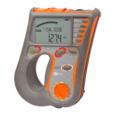
Sonel
Sonel MIC-2510 User manual
Sonel
Sonel MPI-506 User manual
Sonel
Sonel MPI-540 User manual
Sonel
Sonel PQM-702 User manual

Sonel
Sonel LKZ-710 User manual
Sonel
Sonel MIC-5010 User manual

Sonel
Sonel TDR-420 User manual
Sonel
Sonel MPI-530-IT User manual
Sonel
Sonel MRU-30 User manual
Sonel
Sonel MIC-2511 User manual

