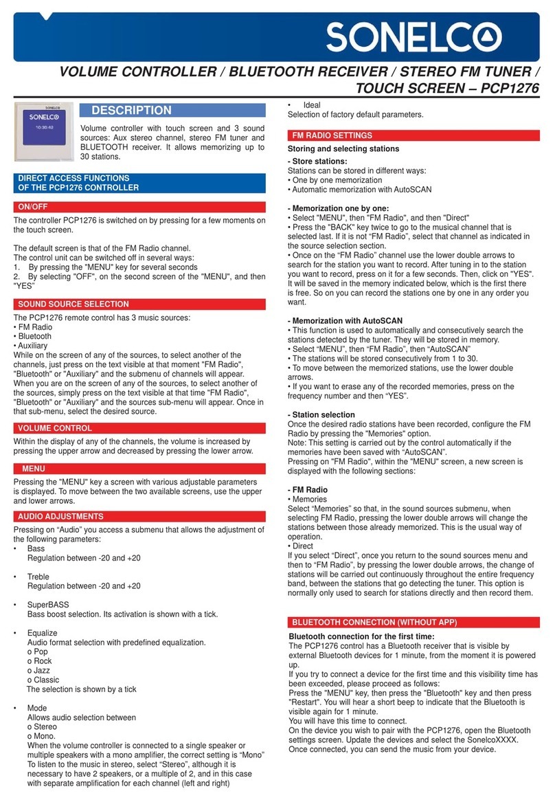
Sonelco PCP1275 User manual

DESCRIPTION
Control with 2 stereo channels and FM radio, auxiliary channel, alarm clock, calendar,
auto-off, and IR receiver for remote control (optional).
CONNECTION
OPERATION
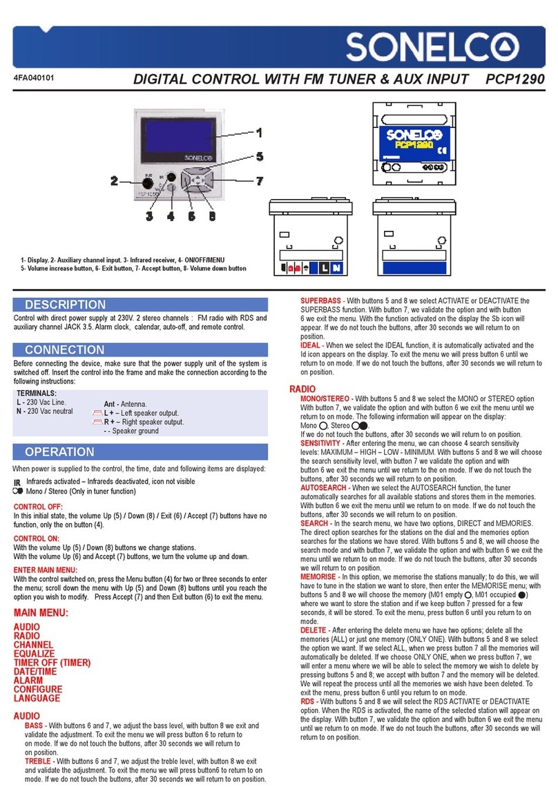
1- Display. 2- Auxiliary channel input. 3- Infrared receiver, 4- Channel button
5- Volume increase button, 6- Exit button, 7- Accept button, 8- Volume down
button, 9-Mono/stereo switch, 10- Antenna.
Before connecting the device, make sure that the power supply unit of the system is
switched off. Insert the control into the frame and make the connection according to the
following instructions:
NOTE: The wiring of the system must be installed separately from the electricity
mains, according to regulations.
When power is supplied to the control, the time, date and following items are displayed:
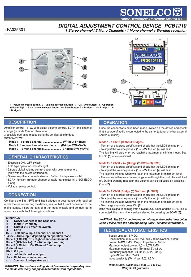
TERMINALS:
2 – Input + 16V power supply.
3 – Output + 16V after switch.
4 – Ground.
15 – Channel 1 input – left..
16 – Channel 1 input – right
25 – Channel 2 input – left..
26 – Channel 2 input – right.
L – Left speaker output.
R – Right speaker output.
- - Speaker ground
4FA039401 DIGITAL CONTROL WITH FM TUNER - 2 CHANNELS PCP1275
Alarm activated – Alarm deactivated, icon not visible
Timer off activated – Timer off deactivated, icon not visible
Infrareds activated – Infrareds deactivated, icon not visible
CONTROL OFF:
In this initial state, the volume Up (5) / Down (8) buttons have no function, Channel
button (4) passes from one audio source to another.
Switch audio on by pressing and holding Exit (6) button.
Enter menu by pressing and holding Accept (7) button.
CONTROL ON:
With the volume adjustment Up (5) / Down (8) buttons.
Change station by pressing and releasing Exit (6) and Accept (7) buttons. Switch
audio off by pressing and holding Exit (6) button.
Enter menu by pressing and holding Accept (7) button.
ENTER MENU:
Once inside the menu, we will browse using the Up (5), Down (8), Accept (7)
and Exit (6) buttons.
MENU:
AUDIO
1 On/Off
1.1. From the initial screen with the Exit (6) button.
1.2 AUDIO/CHANNEL Menu.
1.3 With remote control: press button
2 Change audio source
2.1 Menu: AUDIO/CHANNEL
2.2. From the initial screen with the Channel (4) button.
2.2 With remote control: with audio on, press buttons.
to toggle between channels 1-2, button to toggle
between radio and channels 1-2, button to toggle between any audio
source and the auxiliary channel.
3 Change volume
3.1 Menu: with audio on, Up/Down buttons.
3.2 With remote control: Press buttons
4 Change bass tones between 0 and 100
4.1 Menu: AUDIO/BASS.
4.2 With remote control: press BASS +/-
5 Change trebles tones between 0 and 100
5.1 Menu: AUDIO/TREBLE.
5.2 With remote control: press TREB +/-
6 Jazz, Classical, Pop, Rock Equalization
6.1 Menu AUDIO/EQUALIZATION.
6.2 With remote control: sequentially press button and
7 Superbass activation/deactivation
7.1 Menu: AUDIO/SBASS.
7.2 With remote control: press button.
8 Change balance between LEFT 50-0, CENTRED, RIGHT 0-50
8.1 Menu: AUDIO/BALANCE.
9 Ideal sound – bass, treble, audio volume, call receiving volume, alarm buzzer
volume (factory preset values)
9.1 Menu: AUDIO/IDEAL
9.2 With remote control: press and hold button.
10 Tuning in the next station
10.1 With remote control: press button with audio on radio.
11 Tuning in a specific frequency
11.1 With remote control: sequentially press the button, keying in the
frequency without the decimal sign, from 876 to 1080.
12 Tuning in the frequency saved in a specific memory
12.1 Menu: AUDIO/RADIO/MEM X.
12.2 With the remote control and with the audio on radio, press the memory number
using button to
or pressing buttons
13 Storing the current frequency in a specific memory.
13.1 With remote control: sequentially press button and the memory number,
pressing buttons to
14 Storing the current frequency in the next free specific memory
14.1 With remote control: sequentially press buttons and with the
audio on radio.
STATUS
1 Change alarm state
1.1 STATE/ALARM/INACTIVE to deactivate the alarm
1.2 STATE/ALARM/BUZZER to activate the alarm with
buzzer, the time and minutes will be selected on the following screens, as well as
the alarm buzzer volume and the days of the week when we want it to be active.
1.3 STATE/ALARM/AUDIO to activate the alarm with the
current audio, the time and minutes will be selected on the following screens,
and the days of the week when we want it to be active.

2 Change state of timed off
2.1 STATE/TIMED OFF/INACTIVE to deactivate the timed off
2.2 STATE/TIMED OFF/30 or 60 o 90 MIN to activate the timed off at 30, 60 or 90
minutes.
3 Infrared activation/deactivation
3.1 STATE/INFRARED/INACTIVE to deactivate the infrareds.
3.2 STATE/INFRARED/ACTIVE to activate the infrareds.
CONFIGURATION
1 Radio
1.1 Toggle radio sensitivity between MINIMUM, LOW, HIGH AND MAXIMUM
1.1.1 CONFIG/RADIO/SENSITIV. menu
1.1.2 With the remote control and with the domotic control off, press and hold a
button from (maximum) to (minimum) for a while.
1.2 Toggle radio between MONO and STEREO
1.2.1 CONFIG/RADIO/(STEREO/MONO) menu
1.2.2 With the remote control and with the domotic control off, press BUTTON
and hold for a while
1.3 Search and automatic storage of stations.
1.3.1 CONFIG/RADIO/AUTO SEARCH menu
1.3.2 With the remote control and with the domotic control off, press and hold
button providing that button has not been pressed before.
1.4 Search and manual storage of stations.
1.4.1 CONFIG/RADIO/MAN. SEARCH menu
1.4.2 With the remote control and with the domotic control set on radio, press
button to find the stations and sequentially press button
and a button from to
1.5 Delete 1 station memory
1.5.1 CONFIG/RADIO/DELETE MEM/ONLY ONE menu
1.5.2 With the remote control and with the domotic control set on radio, press
button and hold for a while providing that the button has not
been pressed before.
1.6 Delete all the station memories
1.6.1 CONFIG/RADIO/DELETE MEM/ALL menu
2 Change time
2.1 CONFIG/TIME Menu.
3 Change date
3.1 CONFIG/DATE Menu.
4 Change language
4.1 CONFIG/LANGUAGE Menu.
5 Change backlight
5.1 CONFIG/BACKLIGHT/ACTIVE menu to change backlight when we are using the
control.
5.2 CONFIG/BACKLIGHT/INACTIVE to change the
backlight when more than 45 seconds have elapsed since the control was used.
6 Consult the version
6.1 CONFIG/VERSION to consult the software version
TECHNICAL CHARACTERITICS
Power supply voltage: 16Vdc
Maximum consumption: 475 mA; consumption on standby 50 mA.
Rated output power: 1+1W RMS; Output impedance: 8 Ohm
Maximum output power: 1.5+1.5W RMS;
Distortion < 1%
Maximum output current (Terminal 3): 2 A
Frequency response: 90Hz-18KHz (-3dB)
Signal/Noise ratio: >55 dB
Input sensitivity (Terminals 15,16, 25, 26):1.1 V
Crosstalk: 38 dB
ASSEMBLY RECOMMENDATIONS: All the “COMPACT” series modules can be placed over the various types of embedded boxes,
for which we have various types of front frames that are delivered separately. For further details please see www.sonelco.com
These characteristics are provided for information purposes only. The manufacturer reserves the right to make modifications without prior notice in order to improve the product PCP1275 22-01-14
INSTALLATION EXAMPLE
To chanel 2, connections 25/26
To chanel 1
connections 15/16
As an option, it is possible to install remote
control PC3810 and a PC3811 plug.
To sound diffusers

Instructions for installation of bluetooth
Safety during installation
The installation must be performed by a person properly qualified in electrical engineering. Before commencing
the installation, always disconnect mains voltage.
During installation of the bluetooth, the following conditions must be observed:
•The bluetooth mounting box must be placed flush with the plaster.
•In case of problems with a “sunk” mounting box, the VK1 or VK2
spacer (distance) rings must be used in order to prevent deformation of the
fittings when the screws are tightened.
•The switch is fastened in the mounting box though a sheet-metal
frame by means of two screws of 3 mm diameter (Fig.1,2).
•Position the frame correctly, see Fig. 2, lugs marked with arrows
•To install multiple fitting assemblies, it is necessary to use multiple
boxes with the spacing of centres of 71 mm.
•It is recommended to place the bluetooth in the mounting boxes at
the approximate depth of 40 mm.
•Plastic base segment, pos. 3, snap on the sheet metal frame
•In the bluetooth switch, pos. 4, strip insulation and connect the
wires according to the wiring diagram. Then insert the bluetooth unit in the
base segment, pos. 3, together with the sheet metal frame, pos. 2, until the
bluetooth is locked with the lugs positioned on the sides.
•Put the frame, pos. 5 (wood, metal, plastic, etc.) on the base segment, pos. 3
•Finally, fit the visible component - intermediate frame, pos. 6
Disassembly of bluetooth
•Use a flat screwdriver and slide the intermediate frame out carefully
•Then remove the frame
•Finally, remove the complete bluetooth device using the screwdriver.
The product contains no hazardous substances; after expiration of its service life, it must be handled in
conformity with the waste act in force or pertinent related regulations.
Other Sonelco Controllers manuals

