Sontay GL-CO-RFG361 User manual
UK Sales Tel: 0845 345 7253 International Tel: +44 1732 861225
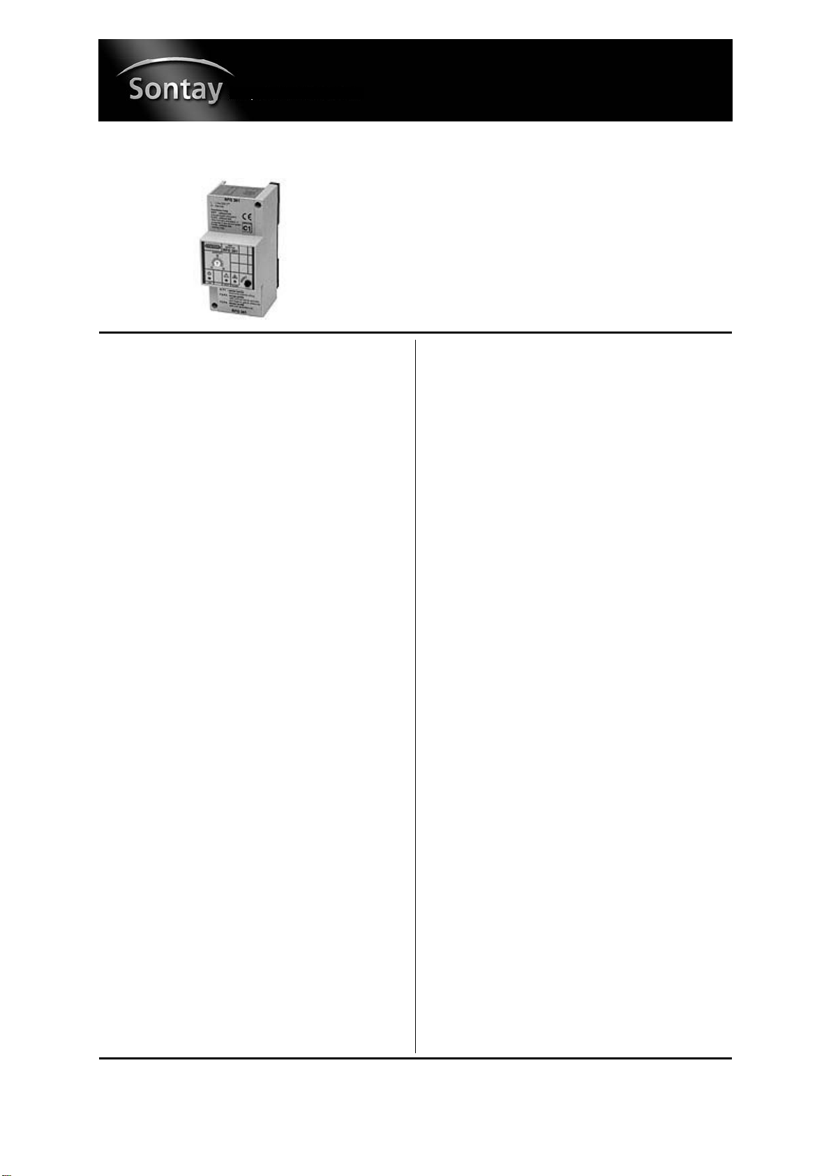
1-Channel Gas Leak Alarm System
Page 1 of 4
GL-CO-RFG361
Issue: 5.5
Date Of Issue: 28/10/2008
© 2008 Sontay Limited. All rights reserved.
Features
Specification Product Codes
• Remote sensor for Natural Gas, LPG or CO
• Audio & visual alarms
• DIN rail or panel mounting
Power supply 230Vac ±10% @ 50/60Hz
Power consumption 3VA
Radio disturbance VDE0875/0871
Vibration test with 2g (DIN 40046)
Relay output SPDT, 250V @ 5 (1) A
Housing dimensions 115 x 53 x 70mm
Housing materials:
Cover ABS
Base Nylon
Housing protection IP30
Sensor dimensions 77 x 77 x 44
Sensor material Nylon
Sensor protection IP44
Ambient:
Storage temp. -25 to + 60°C
Operating temp.0 to 45°C
RH Class F Din 40040
Country of origin Italy
GL-CO-RFG361
1 Channel gas leak alarm system (DIN rail mount)
GL-CO-RFG-FMK3
Panel door mounting kit
GL-CO-SRS150
Natural gas sensor
GL-CO-SRS250
LPG, Propane sensor
GL-CO-SRS350
Carbon Monoxide sensor
Page 2 of 4
UK Sales Tel: 0845 345 7253 International Tel: +44 1732 861225
GL-CO-RFG361
Issue: 5.5
Date Of Issue: 28/10/2008
© 2008 Sontay Limited. All rights reserved.
Technical Overview Links
The CL-CO-RFG361 is a single channel gas leak alarm sys-
tem. It is designed for the detection of gas leaks in spaces
such as boiler plant rooms, workshops and other industrial
gas installations, to provide safety alarm and shutdown
facilities on detection of gas leakage.
Installation
1. The GL-CO-RFG361 should only be installed by a compe-
tent, suitably trained technician, experienced in installa-
tion with hazardous voltages. (>50Vac & <1000Vac or
>75Vdc & 1500Vdc)
2. Ensure that all power is disconnected before carrying out
any work on the GL-CO-RFG361.
3. Maximum cable is 2.5mm², care must be taken not to
over tighten terminals.
4. Separate the base from the cover.
5. If DIN rail mounting clip onto the DIN rail.
6. Make connections as required (see page 4 for examples)
and links as appropriate (see below).
NB It is advised that no more than 2 cables be inserted
into a single terminal. Use external junction boxes if
necessary.
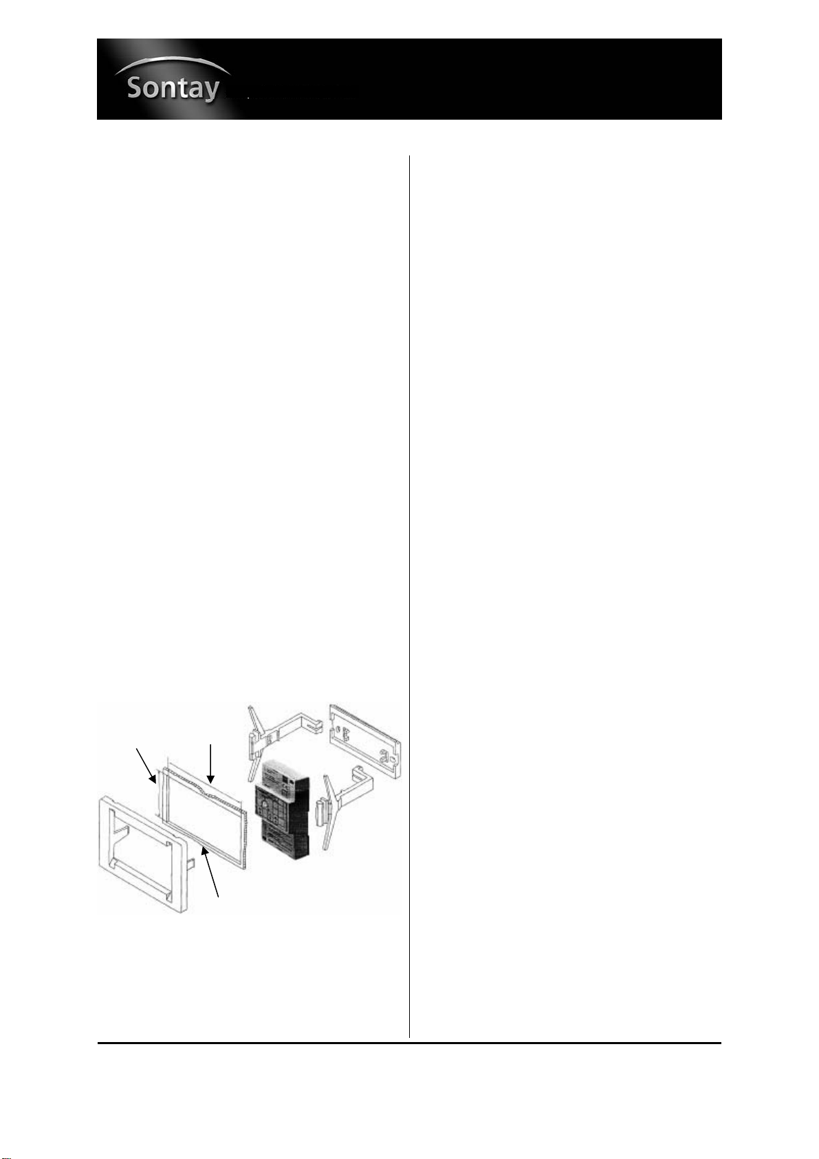
7. Replace the cover on the base using the 2 screws pro-
vided, if panel mounting fix to panel door, using the
panel mounting kit.
Operational Relay Output:
When in alarm:
F2 - F3 linked 1 - 3 closes, 2 - 3 opens
F2 - F3 unlinked 1 - 3 opens, 2 - 3 closes
Latching alarm and Reset:
F3 - F4 linked:
Alarm ceases when the gas concentration falls below the
threshold level and the ALARM LED blinks slowly. Press the
RESET button to clear the LED status.
F3 - F4 unlinked:
Alarm continues even when the gas concentration falls be-
low the threshold level. To deactivate press the RESET but-
ton for at least 5 seconds.
Link functions:
M - F1
No link = Internal buzzer enabled
Linked = Internal buzzer disabled
F2 - F3
No link = Relay normally energised when no gas present
Linked = Relay normally de-energised when no gas present
F3 - F4
No link = Relay with latching alarm
Linked = Relay with non-latching alarm
Alarm Levels
Alarm thresholds
Natural gas alarm threshold:
0.5% to 1.25% (0.8% with sensitivity =0)
(5000 to 12,500ppm)
LPG alarm threshold:
0.22% to 0.56% (0.35% with sensitivity =0)
(2200 to 5600ppm)
CO alarm threshold:
0.02% to 0.5% (0.03% with sensitivity =0)
(200 to 500ppm)
Pre-Alarm thresholds
Natural gas pre-alarm threshold:
0.3% to 0.8% (0.5% with sensitivity =0)
(3000 to 8000ppm)
LPG pre-alarm threshold:
0.14% to 0.35% (0.22% with sensitivity =0)
(1400 to 3500ppm)
CO pre-alarm threshold:
0.012% to 0.03% (0.019% with sensitivity =0)
(120 to 300ppm)
45mm
±0.5mm
63mm
±0.5mm
Panel cut-out
Page 3 of 4
UK Sales Tel: 0845 345 7253 International Tel: +44 1732 861225
GL-CO-RFG361
Issue: 5.5
Date Of Issue: 28/10/2008
© 2008 Sontay Limited. All rights reserved.
Alarm Levels (continued) Self Diagnostics
The alarm threshold for Natural Gas is about 16% of the
LEL. This is below the limit set by the manufacturing stan-
dards (20% LEL). The pre-alarm threshold is about 66.6%
of the alarm threshold. Using the SENSITIVITY pot the
thresholds can be adjusted within the limits established the
manufacturing standards. Turning the pot towards + in-
creases the sensitivity and turning towards - decreases the
sensitivity.
Sensor location
Natural gas 100 to 500mm from the ceiling
LPG 100 to 500mm from the floor
CO 1.5 to 2m from the floor
It is advisable to position sensors at a certain distance from
gas appliances, so as to avoid nuisance triggering.
Boilers & DHW 1 to 2 meters
Gas cookers 2 to 3 meters
Cable Types
Power & relay 1.5mm²
Sensor up to 40m 1.5mm²
Sensor up to 60m 2.5mm²
Operation
When the controller is switched on it remains inactive for 1.5
to 2 minutes with the FAULT and ALARM LEDs flashing, to
allow the sensor to stabilise.
When the gas concentration exceeds the pre-alarm thresh-
old the ALARM LED blinks.
When the gas concentration exceeds the alarm threshold,
after a delay of about 20 seconds:
• The internal buzzer will sound (if enabled)
• The ALARM LED switches ON
• Activates the operational control
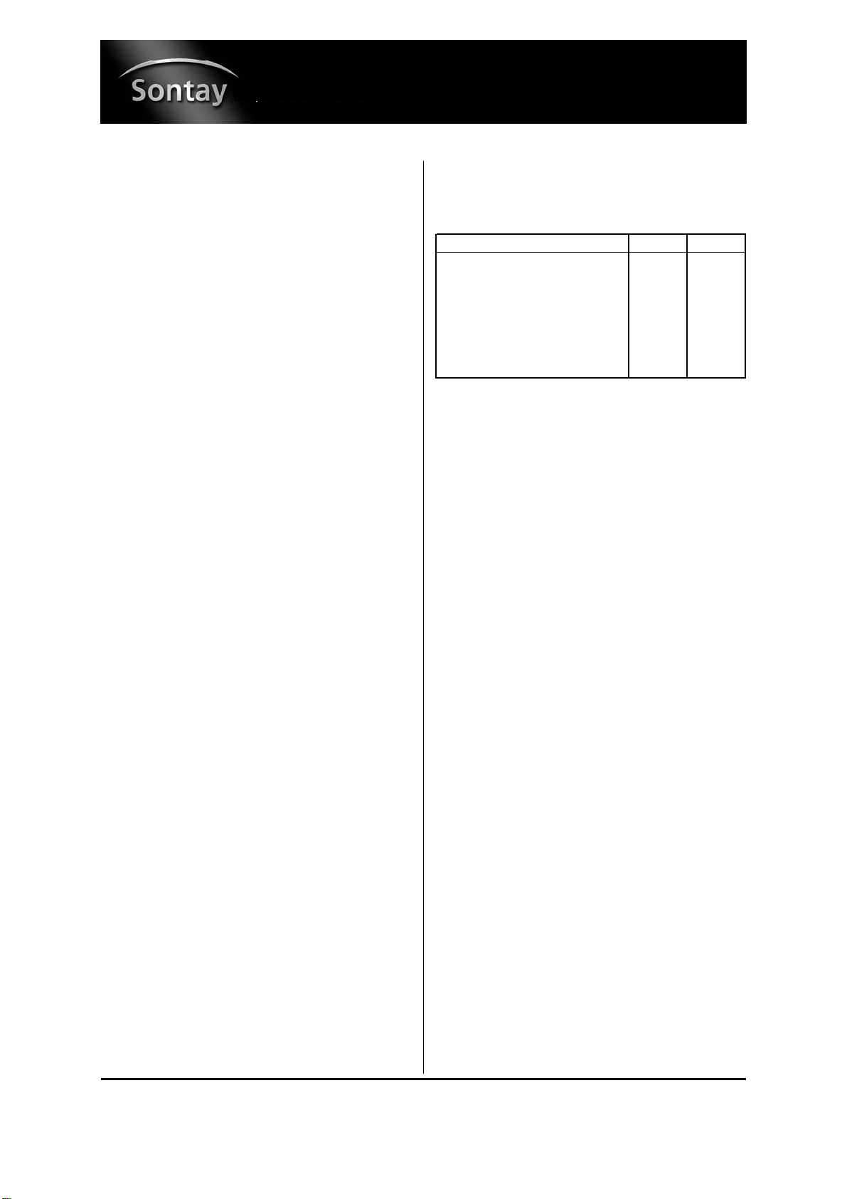
In the event of a fault or incorrect connection of the sensor
the following LED states will occur:
Commissioning
1. Apply power to controller - POWER LED lights.
2. Wait 2 minutes for sensor to stabilise.
3. Set SENSITIVITY pot to ‘0’
4. Simulate presence of gas (gas from a lighter should
work).
5. When the alarm threshold is reached, after a 20 second
delay the ALARM LED will light, the buzzer will sound (if
enabled) and the relay operate.
6. Stop gas simulation. When the concentration falls below
the alarm threshold:
Without latching alarm - buzzer ceases, ALARM LED
blinks slowly
With latching alarm - buzzer continues until RESET button
is pressed for at least 5 seconds.
Gas Shut Off Valve
This must be installed on the gas feed pipe, possibly outside
the space controlled, in a place which is easily accessible
and is protected from bad weather.
NB In LPG installations the valve must be installed down-
stream of the pressure reducing valve.
Type of Fault Fault LED Alarm LED
Sensor self-heating element broken ON OFF
No connection to terminal G ON OFF
No connection to terminal B ON OFF
No connection to terminal M OFF ON
Connections G & B reversed ON OFF
Connections G & M reversed OFF ON
Connections B & M reversed OFF ON

Whilst every effort has been made to ensure the accuracy of this specification, Sontay cannot accept responsibility for damage, injury, loss or
expense resulting from errors or omissions. In the interest of technical improvement, this specification may be altered without notice.
Page 4 of 4
UK Sales Tel: 0845 345 7253 International Tel: +44 1732 861225
For the latest information and product updates, register at www.sontay.com
GL-CO-RFG361
Issue: 5.5
Date Of Issue: 28/10/2008
© 2008 Sontay Limited. All rights reserved.
Dimensions
Front Panel
Example Connections
Basic operations:
Example Connections (continued)
Solenoid valve N/C with reset:
Solenoid valve N/C:
Aeration fan:
Operational
control
Power LED Fault Alarm Reset button
Sensitivity adjustment
This manual suits for next models
4
Other Sontay Security System manuals


