Sony CDU415 User manual

CDU415
CD-ROM Drive Unit
User’s Guide
Mode d’emploi
Bedienungsanleitung
©1997 by Sony Corporation
Rev. 1.0
BKC: 98000268
CDU415
CD-ROM Drive Unit
User’s Guide
Mode d’emploi
Bedienungsanleitung

INFORMATION
You are cautioned that any changes or modifications not expressly approved in this manual
could void your warranty covering this equipment.
Note: This equipment has been tested and found to comply with the limits for a Class B
digital device, pursuant to Part 15 of the FCC Rules. These limits are designed to provide
reasonable protection against harmful interference in a residential installation.
This equipment generates, uses, and can radiate radio frequency energy and, if not installed
and used in accordance with the instructions, may cause harmful interference to radio
communications. However, there is no guarantee that interference will not occur in a
particular installation. If this equipment does cause harmful interference to radio or television
reception, which can be determined by turning the equipment off and on, the user is
encouraged to try to correct the interference by one or more of the following measures:
– Reorient or relocate the receiving antenna.
– Increase the separation between the equipment and receiver.
– Connect the equipment into an outlet on a circuit different from that to which the receiver
is connected.
– Consult the dealer or an experienced radio/TV technician for help.
3
English
2
Owner’s Record
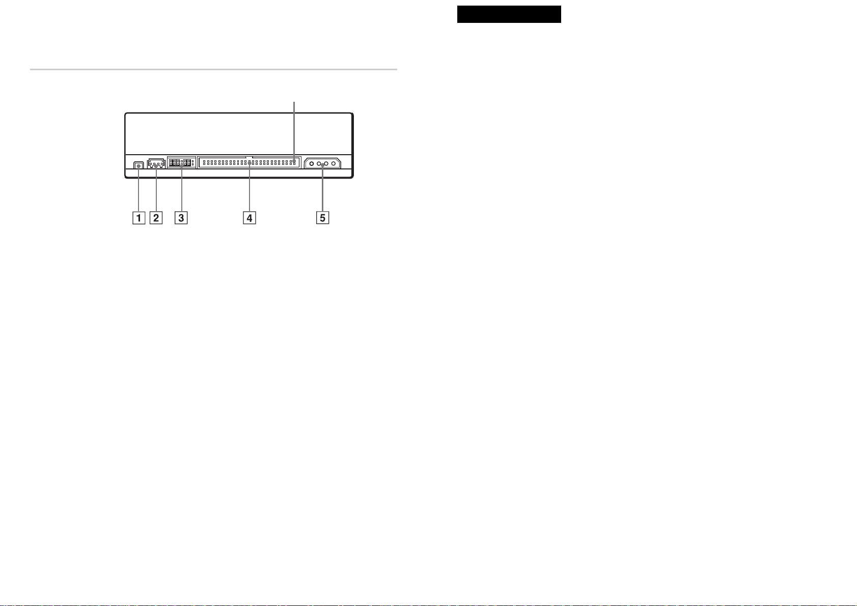
The model and serial numbers are located on the top side of the drive. Record these numbers
in the spaces provided below. Refer to them whenever you call upon your sales representative
regarding this product.
Model No. __________________ Serial No. ___________________
Trademarks
●MS-DOS is a registered trademark of Microsoft Corporation.
●IBM PC, PC/XT, and PC/AT are registered trademarks of International Business Machines
Corporation.
●HP Vectra is a registered trademark of the Hewlett-Packard Company.
●Molex is a registered trademark of Molex, Inc.
●AMP is a registered trademark of AMP, Inc.
●3M is a registered trademark of the Minnesota Mining and Manufacturing Company.
●JAE is a registered trademark of Japan Aviation Electronics Industry, Ltd.
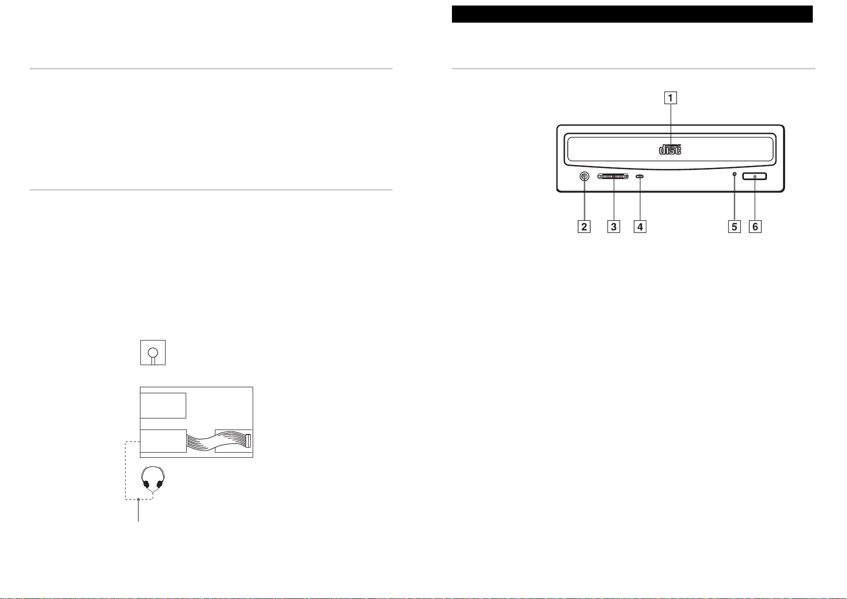
This CD-ROM Drive Unit is classified as a
CLASS 1 LASER PRODUCT.
The CLASS 1 LASER PRODUCT label is
located on the top of the drive.
Bei diesem CD-ROM-Laufwerk CDU415
handelt es sich um ein Laser-Produkt der
Klasse 1. Ein entsprechender Aufkleber mit
der Beschriftung LASER KLASSE 1
PRODUKT befindet sich auf der Oberseite
des Geräts.
CAUTION INVISIBLE LASER RADIATION WHEN OPEN. DO NOT
STARE INTO BEAM OR VIEW DIRECTLY WITH
OPTICAL INSTRUMENTS.
VORSICHT UNSICHTBARE LASERSTRAHLUNG, WENN ABDECKUNG
GEÖFFNET. NICHT IN DEN STRAHL BLICKEN, AUCH
NICHT MIT OPTISCHEN INSTRUMENTEN.
ADVARSEL USYNLIG LASERSTRÅLING VED ÅBNING SE IKKE IND I
STRÅLEN-HELLER IKKE MED OPTISKE INSTRUMENTER.
ADVARSEL USYNLIG LASERSTRÅLING NÅR DEKSEL ÅPNES. STIRR
IKKE INN I STRÅLEN ELLER SE DIREKTE MED OPTISKE
INSTRUMENTER.
VARNING OSYNLIG LASERSTRÅLNING NÄR DENNA DEL ÄR
ÖPPNAD. STIRRA EJ IN I STRÅLEN OCH BETRAKTA EJ
STRALEN MED OPTISKA INSTRUMENT.
VARO! AVATTAESSA OLET ALTTIINA NÄKYMÄTTÖMÄLLE
LASERSÄTEILYLLE. ÄLÄ TUIJOTA SÄTEESEEN ÄLÄKÄ
KATSO SITÄ OPTISEN LAITTEEN LÄPI.
This Label is located on
the top of the drive.
Dieser Aufkleber
befindet sich an der
Oberseite des Gehäuses.
To prevent fire or shock hazard, do not expose the unit
to rain or moisture.
To avoid electrical shock, do not open the cabinet.
Refer servicing to qualified personnel only.
WARNING
This unit uses CD-ROM discs with the following mark.
When you use this unit as a CD player, use compact discs
with the following mark.
CLASS 1
LASER PRODUCT
LASER KLASSE 1
PRODUKT
LUOKAN 1 LASERLAITE
KLASS 1 LASER APPARAT

Introduction
Features The CDU415 is an internal CD-ROM (Compact Disc Read-Only Memory)
drive unit designed for use with an IBM PC, HP Vectra, or compatible
computer. It can read as much as 650 Mbytes of digital data stored in a
single CD-ROM disc.
The CDU415 has the following features:
General
●5 1/4 inch half-height drive form factor.
●Embedded SCSI bus interface (SCSI-2).
●256-kbyte buffer memory.
●Audio CD like drawer loading of a disc without using a caddy.
●Power loading and power eject of a disc. The disc can also be ejected
manually.
●Housed in an airtight frame casing.
●Equipped with a parity on/off switch.
Supported disc formats
●Reads data in CD-ROM, CD-ROM XA, CD-I and CD-I Ready standard
formats.
●Reads data in CD-BRIDGE format including PHOTO-CD.
●Reads standard CD-Digital Audio encoded discs.
●Reads VIDEO-CD and CD EXTRA discs.
Performance
●Supports standard, double and quadruple speed operations with real
time error correction.
●Fast access time ensuring reliable high-speed data access.
Audio
●Outputs 16-bit digital audio data over the SCSI interface.
●Equipped with audio line output and headphones jack for audio CD
playback.
Note:
The CDU415 is not equipped with an ADPCM audio circuitry required to
support CD-ROM XA and CD-I compatible audio modes. In addition, the
unit does not support the CD-I graphic decoding function; it has to be
provided by the system.
Introduction 5
Contents
Introduction 5
Features...................................................................................................5
Software Requirement.............................................................................6
Example of System Setup .......................................................................6
Location and Function of Parts and Controls 7
Front Panel ..............................................................................................7
Rear Panel...............................................................................................8
Precautions 9
Installing the Drive in Your Computer 10
Preparation.............................................................................................10
Setting the Jumpers...............................................................................10
Opening the Computer...........................................................................12
Preparing a Space for the Drive............................................................13
Mounting the Drive.................................................................................14
Connecting the Drive .............................................................................15
Mounting the Host Adapter....................................................................18
Reassembling the Computer .................................................................19
Installing the Software Driver 20
Operating the Drive 21
Starting the Drive...................................................................................21
Ejecting the Disc....................................................................................23
Specifications 24
4 Contents

Location and Function of Parts and Controls 7
Location and Function of Parts and Controls
Front Panel
1Disc drawer
Accepts a CD-ROM disc on its tray.
2Headphones jack
Accepts a stereo headphones set. Analog audio signals are output.
3Volume control
Controls the volume level of sound output from the headphones jack 2.
4Busy indicator
The amber indicator lights up or flashes to indicate one of the following
unit conditions:
●Steady lit: TOC (table of contents) read, seek, data read or audio
playback in progress
●Flashing: Drawer in motion
5Emergency eject hole
Used to open the disc drawer manually when neither the eject button 6
nor a software command works. Insert a pointed object, such as a paper
clip, into this hole and push (approx. 40 mm stroke).
6Eject button
Opens and closes the disc drawer.
Software Requirement
To access data on CD-ROM discs, the appropriate device driver and
MSCDEX (supplied with the host adapter) must be installed in your
computer. See the manual that comes with the host adapter for details.
The application software you need for using the data on a CD-ROM disc
depends on the type and format of the target data. See the manual supplied
with your CD-ROM disc for instructions.
Example of System Setup
To use the CD-ROM drive unit, the following components are required:
●Computer (IBM PC, PC/XT, PC/AT, HP Vectra, or equivalent)
●Host adapter
●Floppy disk drive
●Interface cable (50 to 50 pin flat cable)
●Software (Device driver, Utilities)
The following is an example of system setup.
6Introduction
Software
Host computer
Audio cable
Floppy disk
drive
ID No.3
CDU415
Host adapter
ID No.7

8Location and Function of Parts and Controls Precautions 9
Precautions
■Installation
●Avoid placing the drive in a location subject to:
– high humidity
– high temperature
– excessive dust
– mechanical vibration
– direct sunlight
●The drive can be used in either a horizontal or vertical position.
●Do not force the power cable. It is keyed to protect the drive.
■Operation
●Do not move the drive when it is in use. Doing so may cause data error
and damage the optical pick-up.
●Avoid exposing the drive to sudden changes in temperature as
condensation may form on the lens inside the drive. Should the
surrounding temperature suddenly rise while the drive is turned on, stop
using the drive and leave the power on at least one hour before
operating it or turning it off. Operating the drive immediately after a
sudden increase in temperature may result in a malfunction.
■Transportation
●Close the disc drawer before moving the drive.
●Keep the original packing materials. When you need to ship the drive to
another location, repacking it in its original container will help you
transport it safely.
Rear Panel
1F. GND (Frame ground) tab
Connect to one of the host computer’s ground cables when the drive’s
frame is not in direct contact with the computer.
2AUDIO OUT connector
Outputs analog audio signals.
3SCSI bus setting jumper block
Specifies various SCSI bus settings. See page 11 for details.
4INTERFACE CONNECTOR (SCSI bus)
Connect to the SCSI host adapter using a connecting cable.
5DC INPUT (power-in) connector
Connect to the power supply of the host computer.
Pin 1

Removing the jumper from a jumper pin pair disables its corresponding
function, and installing the jumper enables it.
The recommended jumper for use is AMP Shunts (14227-1), JAE Short
Socket (PS-2SH4-1) or equivalent.
The following table shows the function of each pair of jumper pins.
Notes:
●The lower row of pins are ground.
●ID SELECT, PREVENT/ALLOW, and TEST MODE are recognized
only when the power is turned on or SCSI is reset.
●TEST MODE is reserved for use at the factory only. Do not put a
jumper over TEST MODE pins. Doing so may cause an unexpected
result.
Installing the Drive in Your Computer 11
0 1 2
PARITY
ID SELECT
PREVENT/ ALLOW
TEST MODE
TERM
Installing the Drive in Your Computer
This section provides the basic instructions you need to install the drive
and host adapter in your computer. You should also read the manual of
your computer for specifications of how to install internal devices.
Preparation You need the following parts and tools (these are not supplied with the
drive):
●Aflat-blade screwdriver
●Four screws 3 mm in diameter and 6 mm in length.
●Two mounting rails if your computer has mounting tracks.
Unplug the computer and disconnect the cables attached to the back to
give yourself more room to work. Do not turn on the power of the
computer before completing the entire installation process.
Setting the Jumpers
Set the jumpers on the rear of the drive in accordance with the
configuration of your computer system.
The jumpers are preset as illustrated at the factory.
(default preset value may be changed depending on the configuration)
10 Installing the Drive in Your Computer
201
0
1
2
3
4
5
6
7
The disc drawer can be opened by
pressing the eject button or by a software
command.
The disc drawer cannot be opened either
by the eject button or a software
command.
Jumper Function
PARITY
ID SELECT Assigns the drive’s SCSI ID. Select an ID number
which is not used by other SCSI devices connected
to the bus. ID numbers and corresponding jumper
pin settings are as follows:
ID number
Jumper pin settings
: Without jumper
: With jumper
: Factory setting
TERM : Active terminator OFF
: Active terminator ON (Factory setting)
PREVENT/
ALLOW Enable:
TEST MODE Reserved for use at the factory only.
Disable:
Enables/Disables the SCSI bus parity check
function.

Preparing a Space for the Drive
1Remove the screws and brackets securing the floppy disk drive and the
lower drive bay blanking plate.
2Disconnect the floppy disk drive.
3Remove the floppy disk drive and the blanking plate.
Installing the Drive in Your Computer 13
Opening the Computer
1If your computer has its rear side covered by a plastic panel attached
with plastic hook pad, pull it off.
2Remove the cover mounting screws.
3Remove the cover of the computer.
12 Installing the Drive in Your Computer
Computer Remove plastic panel.
Cover mounting screw
Remove the screws.
Remove the computer cover.
Rear plastic panel
Floppy disk drive
Lower drive bay
blanking plate
Floppy disk drive
Floppy disk drive
Blanking plate

Connecting the Drive
Connect the drive to the computer with the following connectors:
●DC INPUT connector
●F. GND tab (unless the drive’s frame is in direct contact with the
computer’s chassis).
●AUDIO OUT connector (if you plan to connect audio equipment)
●INTERFACE CONNECTOR.
■DC INPUT connector
The power supply cables recommended are those using an AMP-1-480424-0
housing and 170147-1 or 170120 contacts.
The pin assignment is as follows.
After matching the beveled edges, insert the plug of the power supply cable
to the DC INPUT connector and push it firmly in place.
Caution: Improper connection may damage the drive and void the warranty.
Installing the Drive in Your Computer 15
Mounting the Drive
If mounting rails are necessary, attach them to the drive in the same way as
your floppy disk drive and slide the drive into the lower drive bay.
If mounting rails are not required in your system, screw the drive in place.
14 Installing the Drive in Your Computer
Slide the drive into the lower bay.
F. GND tab INTERFACE CONNECTOR
DC INPUT connector
AUDIO OUT
connector
GND
+5 V DC +12 V DC
GND
DC INPUT connector
Power supply cable
(4-pin connection cable)

■INTERFACE connector
1Firmly insert one end of the interface cable into the INTERFACE
CONNECTOR.
2Attach the other end of the cable to the host adapter.
Installing the Drive in Your Computer 17
■F. GND tab
Connect the F. GND tab to one of the host computer’s ground cables
unless the drive’s frame is in direct contact with the computer’s chassis
(a situation not likely under normal circumstances).
The frame ground cable recommended is the one using an AMP 1-480435-0
housing and 170203-2 or 60711-1 contact.
■AUDIO OUT connector
The audio output cables recommended are those using a Molex 08-50-0113
or 08-50-4114 contacts and a 22-01-3047 housing. The pin assignment is as
follows:
16 Installing the Drive in Your Computer
F. GND tab
Frame ground cable
INTERFACE
CONNECTOR
Interface cable
Pin 1
Right signal
GND GND
Left signal Host adapter Interface cable

Mounting the Host Adapter
Install the host adapter in one of the available system expansion slots of
your computer. Refer to the operating instructions included with the host
adapter for complete instructions on installation and settings.
18 Installing the Drive in Your Computer
Reassembling the Computer
1Reinstall the floppy disk drive in the top drive bay.
2Reconnect the cables to the floppy disk drive.
3Fasten the screws and front brackets as they were before.
4Tuck the cables behind the drives so that they do not protrude above the
power supply module.
5After checking the following points, slide the computer’s cover on and
fasten the cover mounting screws at the back of the computer.
●Are the connections between the drive and computer correct?
●Are the jumpers set to the appropriate positions?
6Remount the rear plastic panel and refer back to the proper installation
section if you answered “no” to either of the questions above.
Installing the Drive in Your Computer 19
Reinstall the floppy disk drive.
Tuck the cables.
Power supply
Install the host adapter in
one of the expansion slots.

Operating the Drive
This section describes how to start the drive and eject a disc.
Starting the Drive
1Turn on the power of your computer.
2Press the eject button.
The drawer comes out automatically.
3Place a disc in the drawer with its label side up.
Operating the Drive 21
Installing the Software Driver
The MSCDEX (or equivalent) and a device driver for the CD-ROM
drive are supplied with the host adapter. Install both the MSCDEX
(or equivalent) and the device driver in order to use the CD-ROM drive.
Refer to the manual supplied with the host adapter for instructions.
20 Installing the Software Driver
Place a disc with
its label side up.
Press the eject button.

Ejecting the Disc
To eject the disc, press the eject button on the front panel. The drawer
comes out automatically.
Note:
The eject button does not work if it is disabled by:
- the software you are using
- the PREVENT/ALLOW jumper
■Opening the drawer manually in an emergency
You can open the drawer manually when it fails to come out by means of
the eject button or software commands. To do this, follow the procedure
below:
1Turn off the power of your computer.
2Insert a pointed object, such as a paper clip, into the emergency eject
hole and push.
After removing a disc from the drive unit, consult your dealer or qualified
service personnel.
Operating the Drive 23
Note:
When the drive is set up in vertical position, use the appropriate disc locks
to prevent your disc from falling.
4Gently push the drawer or press the eject button to close the drawer.
The drive may begin reading the Table of Contents (TOC) data when it
accepts the disc. The busy indicator lights up in amber while the drive
is reading the TOC.
For subsequent drive operations, follow the instructions provided with
the application software you are using.
Note:
The busy indicator stays lit in amber if:
– the disc is not properly placed on the loading tray
– a malfunction occurs.
In either case, eject the disc and place it in the loading tray again making
sure that it sits properly in the tray. If doing this does not solve the
problem and the busy indicator still remains lit in amber, consult your
dealer or qualified service personnel.
Caution: Do not forcibly close the disc drawer. Applying excessive force
may damage the loading mechanism. The tray’s mechanism is designed to
operate with a “feather touch”.
22 Operating the Drive
Disc locks
Press the eject button.
Insert a pointed object to
the emergency eject
hole.
Approx. 40 mm

■Environmental conditions
Operating
Temperature 5 °C to 50 °C (41 °F to 122 °F)
Humidity 10 % to 90 % (Max wet bulb 29 °C)
Atmosphere Non-condensing
Non-operating/Storage
Temperature –30 °C to 50 °C (–22 °F to 122 °F)
Humidity 10 % to 90 %
Atmosphere Non-condensing
■Dimensions and Mass
Dimensions Approx. 146 x 41.4 x 208 mm (w/h/d)
(5 3⁄4x 1 11⁄16 x 8 1⁄4inches)
Mass Approx. 0.84 kg (2 lb 3 oz)
■Power requirement
Voltage +5 V DC ± 5 % and +12 V DC ± 10 %
Ripple +5 V DC: ≤100 mVpp
+12 V DC: ≤200 mVpp
Current +5 V DC: 800 mA (typical)
+12 V DC: 300 mA (typical)
■Connectors
(with DC INPUT connector) AMP 179376-1 or equivalent
AUDIO OUT connector Molex 70066C or G, 700400C or G
and 70430C or G, or equivalent
■Laser
Type Semiconductor laser GaAlAs
Wave length 780 nm
Output power 0.3 mW
Specifications 25
Specifications
■General
Host interface SCSI-2
Disc
Acceptable discs CD-Digital Audio discs
CD EXTRA discs
CD-ROM mode-1 data discs
CD-ROM mode-2 data discs
CD-ROM XA discs (readable)
Audio-combined CD-ROM discs
CD-I discs (readable)
CD-I Ready discs (readable)
CD Bridge discs
Photo CD discs (single and multisession)
VIDEO-CD discs
Disc diameter 12 cm or 8 cm
■Drive performance
Data transfer rate
Sustained rate 150 kbytes/s (1X mode)
600 kbytes/s (4X mode)
1160 –1800 kbytes/s (8X –12X P-CAV mode)
Burst rate 4 Mbytes/s (asynchronous)
10 Mbytes/s (synchronous)
Random access time 130 ms (typical/8X–12X P-CAV mode)
■Reliability
Read error rate (includes retry, with a standard disc)
L-EC on 1 block /10l2 bits
L-EC off 1 block /109bits
■Audio
Output level
Line out 0.75 V at 47 kΩ
Headphone 0.55 V at 32 Ω
24 Specifications

■Dimension diagram
Important:
The overhang of the screws should not exceed 6.0 mm from the surface of
the side panels or the bottom plate.
26 Specifications
(51/2)
(17/8) (31/8)
79.25
47.5
+
+
+
+
139.7
10
(1/32)
(1/32)
21.9(7/8)
(13/32)
0.5 0.4
(111/16)
41.4
5
(111/16)
42.3 203 (8)
146(53/4)
(7/32)
148 (57/8)
Design and specifications are subject to change without notice.
4 M3 mounting screws
(4 on each side)
4 M3 mounting screws
Table of contents
Other Sony DC Drive manuals
Popular DC Drive manuals by other brands

KSB
KSB PumpDrive 2 Eco Installation & operating manual

Hafele
Hafele E-Senso user manual

Inovance
Inovance CS500 user manual

Lamtec
Lamtec 662R2127 Operatoring Instructions

hatch
hatch ELP20-2060-UNV-SD Installation and instructions

SEW-Eurodrive
SEW-Eurodrive MOVIMOT flexible MMF1 C/DBC Series operating instructions