SERVICE MANUAL
Sony Video & Sound Products Inc.
9-896-470-01
2017L33-1
© 2017.12
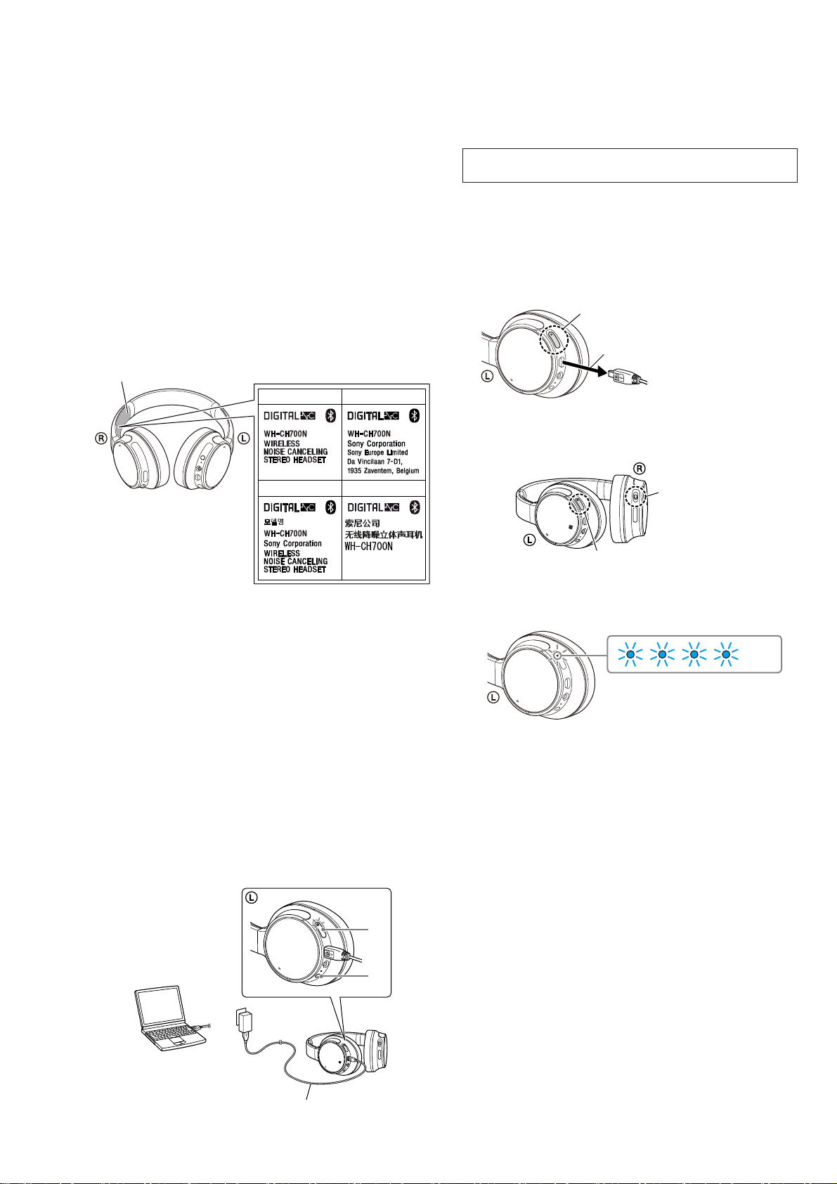
WH-CH700N
SPECIFICATIONS
WIRELESS NOISE CANCELING STEREO HEADSET
US Model
Canadian Model
AEP Model
UK Model
E Model
Australian Model
Chinese Model
Tourist Model
Ver. 1.0 2017.12
(CH)
General
Communication system: Bluetooth Specication version 4.1
Output: Bluetooth Specication Power Class 2
Maximum communication range: Line of sight approx. 10 m
1)
Frequency band: 2.4 GHz band (2.4000 GHz - 2.4835 GHz)
Compatible Bluetooth proles2):
A2DP (Advanced Audio Distribution Prole)
(30 ft)
AVRCP (Audio Video Remote Control Prole)
HFP (Hands-free Prole)
HSP (Headset Prole)
Supported Codec3):SBC4) , AAC5) , aptX, aptX HD
Supported content protection method: SCMS-T
Transmission range (A2DP):
Included items:
Wireless noise canceling stereo headset (1)
20 Hz - 20,000 Hz (Sampling frequency 44.1 kHz)
Micro-USB cable (approx. 50 cm (19 3/4 in.)) (1)
Headphone cable (approx.1.2 m (47 1/4 in.)) (1)
Reference Guide (1)
Operating Instructions (1)
Other documents (1 set) (US, CND, AEP, UK, CH, LA only)
1) The actual range will vary depending on factors such as
obstacles between devices, magnetic elds around a microwave
oven, static electricity, reception sensitivity, antenna’s
performance, operating system, software application, etc.
2) Bluetooth standard proles indicate the purpose of Bluetooth
communications between devices.
3) Codec: Audio signal compression and conversion format
4) Subband Codec
5) Advanced Audio Coding
Wireless noise canceling stereo
headset
Power source:
DC 3.65 V:Built-in lithium-ion rechargeable battery
DC 5 V: When charged using USB
Mass: Approx.240 g (8.47 oz)
Operating temperature: 0 °C to 40 °C (32 °F to 104 °F)
Usage hours:
When connecting via the Bluetooth device
Music playback time:
Max. 35 hours (NC ON),Max. 40 hours (NC OFF)
Communication time:
Max. 35 hours (NC ON),Max. 40 hours (NC OFF)
Standby time:
Max. 35 hours (NC ON),Max. 200 hours (NC OFF)
When connecting via the headphone cable with NC ON:
Max. 50 hours
Note: Usage hours may be shorter depending on the Codec
and the conditions of use.
Charging time:
Approx. 7 hours
(About 60 minutes of music playback is possible after
10 minutes charging.)
Note: Charging and usage hours may be dierent depending
on the conditions of use.
Charging temperature: 5 °C to 35 °C (41 °F to 95 °F)
Receiver
Type: Closed, Dynamic
Driver unit: 40 mm
Frequency response:
7 Hz - 20,000 Hz (JEITA) (when connecting via the headphone
cable with the unit turned on)
Impedance:
22 Ω (1 kHz) (when connecting via the headphone cable with
the unit turned on)
48 Ω (1 kHz) (when connecting via the headphone cable with
the unit turned o)
Sensitivity:
97 dB/mW (when connecting via the headphone cable with
the unit turned on)
98 dB/mW (when connecting via the headphone cable with
the unit turned o)
Microphone
Type: Electret condenser
Directivity: Omni directional
Eective frequency range: 50 Hz - 8,000 Hz
System requirements for battery
charge using USB
USB AC adaptor
A commercially available USB AC adaptor capable of feeding in
more than 0.5 A (500 mA)
Personal Computer
(As of December 2017)
Personal Computer with pre-installed with any of the following
operating systems and USB port:
Operating Systems
(when using Windows)
Windows®®
10 Pro
Windows®®
8.1 Pro
Windows®®
8 Pro
Windows®7
8 / Windows
8.1 / Windows
10 Home / Windows
Home Basic / Home Premium / Professional / Ultimate
(when using Mac)
Mac OS X (version 10.9 or later)
Design and specications are subject to change without notice.
Rated power consumption (Except US, CND, LA): 1.2W
Operating frequency (AEP, UK):
Bluetooth 2,400 MHz - 2,483.5 MHz
NFC 13.56 MHz
Maximum output power (AEP, UK):
Bluetooth < 4 dBm
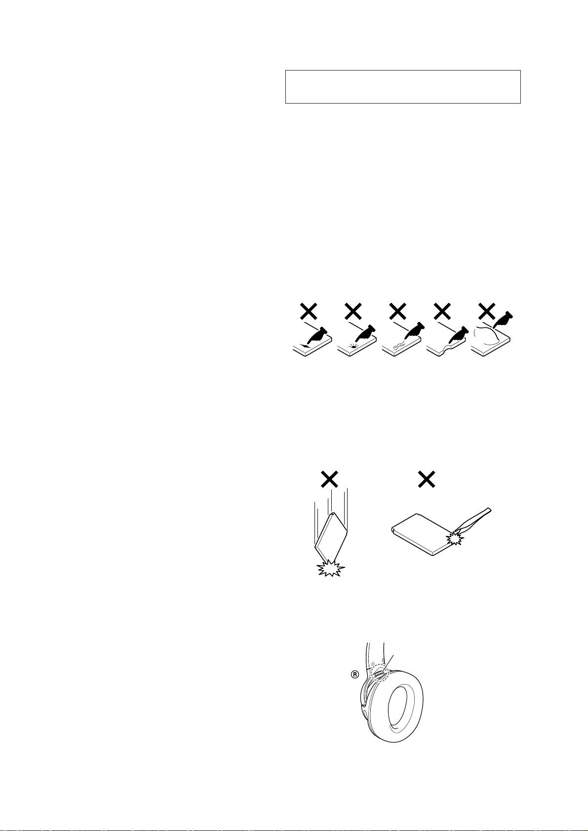
CAUTION
Danger of explosion if battery is incorrectly replaced.
Replace only with the same or equivalent type.
注意
如果电池更换不当会有爆炸危险
只能用同样类型或等效类型的电池来更换
柵䋫剧♘濕3511!NI{!.!3594/6!NI{
⌵⭨∃䋫濕Ŭ!31!eCn濃FJSQ濄
The validity of the CE marking is restricted to only those countries
where it is legally enforced, mainly in the countries EEA (European
Economic Area).
The Bluetooth® word mark and logos are registered trademarks
owned by the Bluetooth SIG, Inc. and any use of such marks by
Sony Corporation is under license.
The N-Mark is a trademark or registered trademark of NFC Forum,
Inc. in the United States and in other countries.
Windows is a registered trademark or trademark of Microsoft
Corporation in the United States and/or other countries.
Mac, OS X,iPhone and iPod touch are trademarks of Apple Inc.,
registered in the U.S. and other countries.
“Made for iPod” and “Made for iPhone” mean that an electronic
accessory has been designed to connect specically to iPod or
iPhone, respectively, and has been certied by the developer to
meet Apple performance standards.Apple is not responsible for
the operation of this device or its compliance with safety and
regulatory standards. Please note that the use of this accessory
with iPod or iPhone may aect wireless performance.
Qualcomm® aptX™ audio is a product of Qualcomm Technologies
International, Ltd.
Qualcomm is a trademark of Qualcomm Incorporated, registered in
the United States and other countries, used with permission. aptX
is a trademark of Qualcomm Technologies International, Ltd.,
registered in the United States and other countries, used with
permission.
Android is a trademark of Google Inc.
Other trademarks and trade names are those of their respective
owners.


 User manual")